Subscribe to Our Youtube Channel
Summary of Contents for Flowmetrics PA-1001A Series
- Page 1 INSTALATION, OPERATION & MAINTENANCE MANUAL PA-1001A Series SIGNAL CONDITIONER & CONVERTORS PA1001A – 7/02 Page 1 of 11...
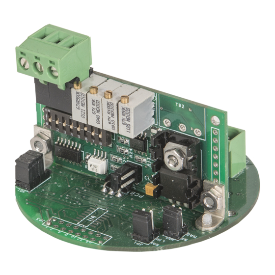
- Page 2 SIGNAL CONDITIONER & CONVERTERS PA1001A Series INTRODUCTION: The PA1001A series preamplifiers/signal conditioners and converters are suitable for use with either magnetic or RF type pickup coils and allow convenient interfacing with process measuring devices and digital electronics. When used with Magnetic type pickups they accept low level signals and produces a pulse output, while providing rejection of unwanted noise and false signals.
-
Page 3: Characteristics And Specifications
CHARACTERISTICS AND SPECIFICATIONS: POWER INPUT: • Voltage: 8-30 VDC • Current Draw: 125mA @ 24VDC, with all options equipped. • Reverse polarity protected PICKUP INPUT: RF Pickup: • Modulation Carrier Frequency: 20KHz • Input Frequency: 2 Hz to 5KHz, adjustable trigger level •... - Page 4 ENVIRONMENTAL: • OPERATING: -40°C TO 85°C • STORAGE: -40°C TO 150°C ENCLOSURES: • Unit is intended for mounting in a conduit box and comes with 2 ½” on center mounting holes. An optional explosion proof or NEMA-4x enclosure is available upon request. APPROVALS: •...
- Page 5 Wiring For RF Pickup Coil: 1. Connect a two conductor shielded cable from the pickup to Terminals 5 and 6. Connect the shield to Terminal 4 (see Figure 1). NOTE: It is also preferable that the pickup coil be grounded to the shield.
- Page 6 Wiring For Magnetic Pickup Coil: 1. Connect a two conductor shielded cable from the pickup to Terminals 1 and 2. Connect the shield to Terminal 4 (see Figure 2). NOTE: It is also preferable that the pickup coil be grounded to the shield.
- Page 7 Analog Output Option: 1. For current output, wire two conductor, shielded cable to terminals 2 (common) and 3 (current output). 2. For voltage output, wire two conductor, shielded cable to terminals 2 (common) and 1 (voltage output). PA1001A – 7/02 Page 7 of 11...
-
Page 8: Controls And Adjustments
CONTROLS AND ADJUSTMENTS: STANDARD PRE-AMPLIFIER ADJUSTMENTS: CARRIER ADJUSTMENT: A twenty turn control used to precisely tune the specific sensing depth, wall thickness, material type, air gap, etc. of the RF pickup coil. RF TRIGGER: A twenty turn control used to set the trigger level of the RF coil input above the ambient noise level. -
Page 9: Calibration Procedure
ANALOG OUTPUT ADJUSTMENTS (PCA-121): 20mA ADJ A twenty turn adjustment which is used to set current output to the desired span corresponding to the equivalent full scale range. (i.e. 20 mA at 100 RPM). 4mA ADJ A twenty-turn adjustment that is used to set the current output signal to the desired zero value. - Page 10 FOR CURRENT OUTPUT: • Connect a digital milliampmeter or equivalent, across the current output terminals. • On the PCA-121 select the “Coarse Range Adj” that corresponds to the maximum input frequency. Refer to Table - 1 for selection options. • Adjust “4mA ADJ”...
- Page 11 Ordering Information PA-1001A Series: Options: 1 = Pulse Output 1A = Pulse and Analog output 1PS = With pulse scaling Mounting: C = Explosion Proof Enclosure B = Nema-4X Enclosure P = Panel Mount Operating Voltage: 1 = 24 VDC (8 to 30 VDC) 2 = 110 VAC 50/60 Hz 3 = 220 VAC 50/60 Hz Electrical Interface...


Need help?
Do you have a question about the PA-1001A Series and is the answer not in the manual?
Questions and answers