
Related Manuals for Flowmetrics 918 RTP


Summary of Contents for Flowmetrics 918 RTP
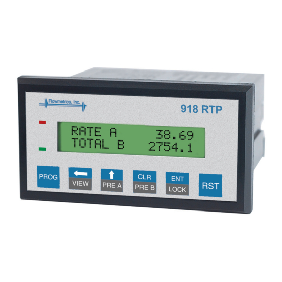
- Page 1 918 RTP Pulse Input Ratemeter and Totalizer INSTALLATION & OPERATING INSTRUCTIONS 99828 08/27/01...
- Page 2 Proprietary Notice The information contained in this publication is derived in part from proprietary and patent data. This information has been prepared for the expressed purpose of assisting operating and maintenance personnel in the efficient use of the instrument described herein. Publication of this information does not convey any rights to use or reproduce it or to use for any purpose other than in connection with the installation, operation and maintenance of the equipment described herein.
-
Page 3: Table Of Contents
TABLE OF CONTENTS SAFETY INSTRUCTIONS ............1 DESCRIPTION & SPECIFICATIONS .......... 2 MOUNTING ................. 3 WIRING ..................3 PROGRAMMING MENU ............. 5 PROGRAMMING FLOWCHART ..........7 ANALOG OUTPUT CALIBRATION ..........13 SOLDER JUMPERS ..............13 WARRANTY ................14 DECODING PART NUMBER ............14... - Page 4 THIS PAGE IS BLANK...
-
Page 5: Safety Instructions
SAFETY INSTRUCTIONS The following instructions must be observed. • This instrument was designed and is checked in accordance with regulations in force EN 60950 (“Safety of information technology equipment, including electrical business equipment”). A hazardous situation may occur if this instrument is not used for its intended purpose or is used incorrectly. -
Page 6: Description & Specifications
PULSE INPUTS reset. If both presets are assigned to same counter, with The 918 RTP can accept two pulse inputs ( A&B ). It Relay A duration set to 00.0 and Preset A lower than Preset computes rate and total of A, B, A+B and A-B. For both B, Relay A pulls in at Preset A and drops out when Preset B inputs the user can define up to 16 points of “k”... -
Page 7: Mounting
MOUNTING HOW TO MOUNT: Slide the body of the unit through the rubber gasket. Tighten the screws evenly and alternately. A panel less Insert the unit into the panel. Slide the brackets up the than .1" may distort if the clamps are screwed too tightly. groove to press against the back of the panel. - Page 8 WIRING (CONTINUED) TERMINAL DESIGNATIONS: TYPICAL WIRING HOOKUPS: 1 • AC1 (115 VAC) 2 • AC2 (115 VAC) INPUT A 3 • RELAY B 4 • COMMON 5 • RELAY A 6 • COMMON 7 • (+) 20VDC OUT (50mA) 8 • (–) 20VDC OUT (50mA) 9 •...
-
Page 9: Programming Menu
The unit is capable of showing nine different parameters. The parameters are the readings 918 RTP gives after a pulse input Each counter can be reset to zero or disabled. The Grand Total is given to it. The parameter names are fixed in Default Mode is programmable and can be set to follow any of the remaining and are user programmable in Message Mode. - Page 10 PROGRAMMING MENU (CONTINUED) Setup Security: Setup Comm port : Unauthorized front panel changes can be prevented by entering In this menu, the unit can be assigned a unique ID and the a user selectable four digit code. The unit can be in LOCK ALL communication parameters, i.e.
-
Page 17: Analog Output Calibration
ANALOG OUTPUT CALIBRATION Analog Output Calibration Procedure: The calibration of the 918 RTP can be done in the following way : Connect the following circuit to terminal pins 11 and 12, i.e Analog O/P (+) and Analog O/P (-). LOAD –... -
Page 18: Warranty
Decoding Part Number NOTE TO OUR CUSTOMER Example: 918 RTP Series: 918 RTP= ........Pulse Input Ratemeter KEP is dedicated to providing complete cus- Totalizer Operating Voltage: tomer service and customer satisfaction. If A= 110 VAC ± 15% B= 220 VAC ± 15%...
Need help?
Do you have a question about the 918 RTP and is the answer not in the manual?
Questions and answers