Advertisement
Quick Links
Service Manual
Safety & Precautions ........................................................................................................................... 3
Electronic Controls ............................................................................................................................. 4
ENERGY STAR 6.1 Start-Up System Check .......................................................................................... 6
Sequence of Operation & Operational Parameters ............................................................................... 7
Error Codes & Troubleshooting ......................................................................................................... 19
Reference Information ...................................................................................................................... 35
Ductless Multi-Split Heat Pump
• Please read this manual before using the heat pump.
• Keep this user manual for future reference.
Table of Contents
2U18MS2HDA
3U24MS2HDA
4U36MS2HDA
ASH218JCDDA
ASH324JCDDA
ASH436JCDDA
PAGE 1
Advertisement

Subscribe to Our Youtube Channel
Related Manuals for Haier GE 2U18MS2HDA


Summary of Contents for Haier GE 2U18MS2HDA
-
Page 1: Table Of Contents
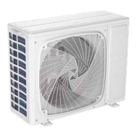
Ductless Multi-Split Heat Pump Service Manual 2U18MS2HDA 3U24MS2HDA 4U36MS2HDA ASH218JCDDA ASH324JCDDA ASH436JCDDA • Please read this manual before using the heat pump. • Keep this user manual for future reference. Table of Contents Safety & Precautions ........................... 3 Electronic Controls ..........................4 ENERGY STAR 6.1 Start-Up System Check .................. - Page 2 Type Model # Appearance 2U18MS2HDA 3U24MS2HDA ASH218JCDDA ASH324JCDDA Outdoor Unit 4U36MS2HDA ASH436JCDDA PAGE 2...
-
Page 3: Safety & Precautions
Safety & Precautions • Read these Safety Precautions carefully to ensure correct installation. • This manual classifies the precautions by WARNING and CAUTION. • Follow all precautions below. They are all important for ensuring safety and preventing property/equipment damage. WARNING: Failure to follow any of WARNING is likely to result in grave consequences such as death or serious injury. CAUTION: Failure to follow any of CAUTION may, in some cases, result in grave consequences. -
Page 4: Electronic Controls
Electronic Controls Outdoor Unit Introduction The outdoor unit features a variable speed, rotary type compressor that delivers refrigerant flow to up to 4 individual indoor units. The system uses R-410A refrigerant mixed with PVE oil, and is 208/230 VAC, 60 Hz, single phase. Compatible indoor units are High wall, Cassette, and Ducted with remote control, cassette with either remote or wired control, and ducted with wired control only. - Page 5 PCB Overview 2U18MS2HDA Module Power Internal Power 3U24MS2HDA 4U36MS2HDA ASH218JCDDA ASH324JCDDA ASH436JCDDA Main Control Board Power CN26/CN27--Reactor filter the harmonic in the current, it connects to main PCB via CN26 and CN27. There will only be 2 capacitors on the board, not 3 as shown. CN9--Communication port between main control board and module board.
-
Page 6: Energy Star 6.1 Start-Up System Check
ENERGY STAR 6.1 Start-Up System Check All new ENERGY STAR certified product lines released as of stop. Please refer to the service manual for this model to cor- February of 2022 will comply with the new 6.1 standards (see rect the error. The automatic testing will need to be manually ENERGY STAR 6.1 requirements). -
Page 7: Sequence Of Operation & Operational Parameters
Sequence of Operation & Operational Parameters Cooling Mode Sequence of Operation Low pressure switch 4-way valve coil: Comp- Refrigerant flow in cooling ressor Refrigerant flow in heating Discharge temp. sensor Gas-liquid separator Muffler High pressure Indoor swtich heat Indoor unit A exchanger Gas stop valve 4-way valve... - Page 8 Cooling Mode Sequence of Operation The vapor will exit the accumulator and enter the compressor. Temperature Sensor Td This cycle will repeat until the demand for cooling ends. The temperature of the compressor discharge hot gas will be monitored by the Discharge Temperature Sensor. If the sen- Temperature Sensor Ts sor reads too hot or cool, the frequency/status of the opera- tion will be adjusted accordingly.
- Page 9 Heating Mode Sequence of Operation Low pressure switch 4-way valve coil: Comp- Refrigerant flow in cooling ressor Refrigerant flow in heating Discharge temp. sensor Gas-liquid separator Muffler High pressure Indoor swtich heat Indoor unit A exchanger Gas stop valve 4-way valve Unit B gas pipe temp.
- Page 10 Heating Mode Sequence of Operation As the outdoor coil absorbs heat from the surrounding air, Temperature Sensor Td the very cold liquid refrigerant boils off and changes to a The temperature of the compressor discharge hot gas will superheated vapor. This vapor travels through the 4-way be monitored by the Discharge Temperature Sensor.
- Page 11 Defrost Cycle Sequence of Operation Multi: Beginning Fixed frequency Indicated FQY 60s Defrosting FQY A (E) Soft startup Compressor Outdoor motor Send defrosting signal to indoor Auto 4-way valve 450-pulse 450-pulse 300-pulse(E) All EEVs Auto open angle Auto open angle All indoor motors ON Anti- cold air fun ction PAGE 11...
- Page 12 Operating Parameters Electronic Expansion Valve (EEV) Control Electronic characteristics Max. open angle 480 pulses Driving speed Open angle limitation of EEV Unit stop Max. open angle Thermostat OFF Min. open angle Cool/ dry 5 pulses 470 pulses 5 pulses 80 pulses Heat 50 pulses 470 pulses...
- Page 13 Operating Parameters Defrost Control In the heating mode and along with the ambient sensor, the defrost sensor monitors the temperature of the outdoor coil to determine if defrost is needed. If the compressor has been running for 10 minutes continuously and for 45 minutes overall, the difference between the ambient sensor (Ta) and the defrost sensor (Te) will be checked.
- Page 14 Remain FQY 105℃ Operating Parameters Increase FQY slowly 1HZ/10S 95℃ Discharge Sensor Protection If the discharge temperature is higher than normal, the compressor will slow down to lower the temperature. Multi: The compressor will shut off if the discharge temperature sensor reaches 243F for 10 seconds.
- Page 15 Operating Parameters High Pressure Protection High Pressure Protection in Cooling Tc--cooling The unit will turn off if there is an abnormal stop three times in one hour. Turn off and restore power to clear error. F(66 Reduce FQY rapidly 2Hz/S F(64 Reduce FQY slowly 1Hz/S F(62...
- Page 16 Operating Parameters Low Pressure Protection The compressor will stop running if the low pressure switch opens for one minute. The compressor will lock out and a low pressure error code will be displayed at the indoor unit if this condition occurs 3 times in an hour.
- Page 17 MULTI: Operating Parameters D: Entering Conditions When the compressor running frequency is lower than 58Hz (E) continuously for 8 hrs, the system Oil Return Cycle will enter the oil return cycle.. In the course of mode changeover, manual unit stop or protective The system will enter the oil return cycle when the compressor is operating at low load conditions, or the operating frequency unit stop, the time will be accumulative.
- Page 18 1 minute later after oil return is over Td Tc ‐ >86℉(30 ℃) & Ts Tc2AVE ‐ >86℉(30 ℃) Operating Parameters Tc2AVE< -31℉(-35 ℃) Max. 10 minutes Oil Return in Heating Mode Oil Return in Heating Mode Send oil return signal oil return begins oil return over Inverter compressor...
-
Page 19: Error Codes & Troubleshooting
Error Codes & Troubleshooting Component Testing Outdoor Fan Motor Check that the wiring and plug connections are in good condition. Check the following voltages at connector CN11 on the outdoor unit PCB if the outdoor unit fan motor does not run, or the Service Monitor Board indicates an error code of 09. Set the meter to read DC volts with a minimum voltage range of 350 volts. - Page 20 Component Testing 4-Way Valve The 4-way valve will control the direction of hot gas discharge via an internal slide assembly. The valve has a line voltage solenoid that is energized in heat mode. The solenoid will direct the internal slide to send the hot gas to the indoor coil. During cooling mode de-energized operation, the internal slide will direct compressor hot gas to the outdoor coil.
- Page 21 Component Testing 2U18MS2HDA / ASH218JCDDA 3U24MS2HDA / ASH324JCDDA EEV (6-pin, 5 wire) White Yellow Orange Blue White 92 Ω 92 Ω 92 Ω - 46 Ω Yellow 92 Ω 92 Ω - 46 Ω Orange 92 Ω - 46 Ω Blue - 46 Ω...
- Page 22 Error Codes Error Code Diagnosis Outdoor PCB EEPROM fault IPM fault Communication failure between IPM and PCB Compressor overload protection Unreliable power input Compressor discharge temperature too high Outdoor fan motor fault Defrost sensor fault Compressor suction temperature sensor fault Outdoor ambient temperature sensor fault Precautions For Adding Refrigerant Compressor discharge temperature sensor fault...
- Page 23 Outdoor Unit Error Codes Error codes are displayed on the service monitor board, the PCB LED-1 and the indoor display panel. Temperature Sensor Error Codes The easiest problems to solve will involve codes that are related to potential failure of temperature sensors. Common problems may include loose connections, open or shorted, and out of calibration.
- Page 24 Outdoor Unit Error Codes Pressure-Related Error Codes To protect the compressor, the PCB has a low pressure switch connection at CN13, and a high pressure switch connection at CN12. Pressure Pressure Switch Switch High Pres- High Pres- sure sure Switch Switch Error Code 42 &...
- Page 25 Outdoor Unit Error Codes Error Codes Caused by Abnormal Refrigerant Circuit Error Code 4 Conditions This code indicates the IPM is not communicating with the PCB. Check the wiring and the connections CN9 on the Error Code 8 PCB and CN15 on the IPM. If the connections are good, yet the boards do not communicate and the code will not clear, This code indicates the temperature of the compressor hot check for correct voltage at the IPM CN15 connection.
- Page 26 Outdoor Unit Error Codes Error Codes Related to Compressor, Outdoor Fan & Error Code 23 4-Way Valve This code indicates an IPM thermal overload. This error was generated by a temperature sensor located in the IPM heat sink. Causes of overheating are typically overcharge Error Code 9 of refrigerant, excessively plugged coil, sensor open or This code indicates the outdoor fan motor is not running.
- Page 27 Troubleshooting [4] Communication abnormal between PCB and IPM Control board can not Is the compressor drive module communicate with the input power normal (Test the AC power supply voltage of the compressor driver module for Adjust communication wire module’s power input ACL-ACN: over 4 minutes normal value should between 196- 253VAC)?
- Page 28 Troubleshooting [8] Discharge temperature too high protection Compressor discharge temperature over 115°C. Error Reconnect Is sensor wiring firmly in place? clears within 3 minutes if temperature lowers below 115°C. Error status lock if it occurs 3 times in 1 hour. Possible causes: Is sensor resistance Replace pressure...
- Page 29 Troubleshooting [10] Outdoor defrosting temperature sensor Te abnormal [11] Suction temperature sensor Ts abnormal [12] Outdoor ambient temperature sensor Ta abnormal [13] Discharging temperature sensor Td abnormal Is the sensor wiring Sensor temperature has been detected below or higher than expected, Replace firmly and correctly in or has been detected as a shorted or open circuit...
- Page 30 Troubleshooting [16] Lack of refrigerant or discharging pipe blocked Discharge & suction temperature Td-Ts≥80°C 10 minutes after compressor start. Error status locks if it occurs 3 Is the sensor wiring correct Correct wiring times in 1 hour. and firmly connected? Possible causes: •...
- Page 31 Troubleshooting [18] Compressor motor desynchronizing Motor desynchronizing occurred. Caused by overload, Correct power supply Is supply voltage normal? load sharply fluctuating, abnormal compressor current sensor circuit, or one of the inverter gate drive signals is missing. Is wire connection Correct the wiring between power module according to diagram and compressor correct?
- Page 32 Troubleshooting [42] Open high pressure switch High pressure switch: Switch circuit has been detected open Power off, check if the for 30 seconds (after 3 minute of compressor run time). Error Reconnect pressure switch connection locks if it occurs 3 times in 1 hour. is ok.
- Page 33 Troubleshooting [43] Open low pressure switch Low pressure switch: Switch has been detected Power off, check if the open for 60 seconds (after 3 minute of compressor Reconnect pressure switch connection run time) or open for 30 seconds during standby. is ok.
- Page 34 Troubleshooting [44] High pressure detected in system The minimum temperature value of indoor pipe Tm Power off. Is pressure switch and outdoor Ts is lower than -45 °C during cooling Reconnect wiring connection ok? mode, or minimum temperature value of outdoor Tc and outdoor Te is lower than -45 °C.
-
Page 35: Reference Information
Reference Information Dimensions 2U18MS2HDA 2U18MS2HDA ASH218JCDDA 2U18MS2HDA Air inlet 2 3/4 (70) Liquid Connection Ø All Ports - 1/4 Flare Air inlet Air out 13 5/8 (346) 1 (26) 2 3/4 (70) Handle Liquid Connection All Ports - 1/4 Flare Ø... - Page 36 C unit connection Dimensions 5 1/8 (130) 24 7/8 (632) 13 5/8 (345) Vapor Connection 35 3/8 (900) Ø All Ports - 3/8 flare 4U36MS2HDA ASH436JCDDA 4U36MS2HDA 7 (178) 23 3/8 (595) 7 (178) Air inlet 2 5/8 (68) 1 3/4 (45) Vapor pipe 1 3/4 (45) Ports A, B, C - 3/8 flare...
- Page 37 Piping Diagrams 2U18MS2HDA ASH218JCDDA PAGE 37 REFERENCE INFORMATION...
- Page 38 Piping Diagrams 3U24MS2HDA ASH324JCDDA PAGE 38 REFERENCE INFORMATION...
- Page 39 Piping Diagrams 4U36MS2HDA ASH436JCDDA PAGE 39 REFERENCE INFORMATION...
- Page 40 Wiring Diagrams 2U18MS2HDA ASH218JCDDA PAGE 40 REFERENCE INFORMATION...
- Page 41 Wiring Diagrams 3U24MS2HDA ASH324JCDDA PAGE 41 REFERENCE INFORMATION...
- Page 42 Wiring Diagrams 4U36MS2HDA ASH436JCDDA PAGE 42 REFERENCE INFORMATION...
- Page 43 Outdoor/Indoor Wiring Connections 2U18MS2HDA Outdoor unit ASH218JCDDA Central Supply Power Control Wiring Indoor unit A Indoor unit B Outdoor unit Central Supply Power Control Wiring Sugested Colors Indoor unit A Indoor unit A Indoor unit B =White To Service =Black Indoor unit B Disconnect =Red...
- Page 44 Sensor Resistance Table Model Sensor Name Resistance Branch Vapor Sensor (Tc1) Branch Liquid Sensor (Tc2) Outdoor Ambient Sensor (Ta) 2U18MS2HDA 3U24MS2HDA Condensing Sensor (Tc) 10KΩ @ 77°F 4U36MS2HDA ASH218JCDDA Compressor Suction Sensor (Ts) ASH324JCDDA ASH436JCDDA Defrost Sensor (Te) Inverter Module Sensor (Tfin) Compressor Discharge (Td) 50KΩ...
- Page 45 Sensor Resistance Tables 10KΩ Sensors T (°C) KΩ T (°F) T (°C) KΩ T (°F) -4.0 90.79 87.8 7.83 -2.2 85.72 89.6 7.52 -0.4 80.96 91.4 7.23 76.51 93.2 6.95 72.33 95.0 6.68 68.41 96.8 5.43 64.73 98.6 5.60 61.27 100.4 5.59 10.4...
- Page 46 Sensor Resistance Tables 50KΩ Sensors T (°C) KΩ T (°F) T (°C) KΩ T (°F) 32.0 1877.0 89.6 366.0 33.8 1775.0 91.4 349.3 35.6 1680.0 93.2 333.5 37.4 1590.0 95.0 318.4 39.2 1506.0 96.8 304.1 41.0 1426.0 98.6 290.5 42.8 1351.0 100.4 277.6...
- Page 47 [This page intentionally left blank.]...
- Page 48 SYJS-04-2019REV.D Model#: 2U18MS2HDA 3U24MS2HDA 4U36MS2HDA ASH218JCDDA ASH324JCDDA GE Appliances, A Haier Company ASH436JCDDA Appliance Park, Louisville, KY 40225 ©2022 GE Appliances, A Haier Company Rev Date: Mar. 2022...
Need help?
Do you have a question about the GE 2U18MS2HDA and is the answer not in the manual?
Questions and answers