Table of Contents
Advertisement
Quick Links
Advertisement
Table of Contents

Related Manuals for PiiGAB M-Bus 900


Summary of Contents for PiiGAB M-Bus 900
- Page 1 Manual for PiiGAB Start Kit 3...
-
Page 2: Table Of Contents
M-Bus communication with PiiGAB 900 gateway .................. 13 Read PiiGAB 900 primary and secondary addresses ................13 Read M-Bus voltage and M-Bus current from PiiGAB 900 ..............14 M-Bus communication with RELAY PadPulse M2 ................... 15 Change primary address of PadPulse M2 ................... 16 Read both primary and secondary address from RELAY PadPulseM2 .......... -
Page 3: Introduction
PiiGAB 900’s internal meter over M-Bus ASCII ..................28 M-Bus-ASCII tag file..........................29 Introduction This document will describe how to configure PiiGAB Start Kit 3 with PiiGAB 900 and RELAY PadPulse M2 communicating over M-Bus, Modbus and M-Bus ASCII communication. Requirments ... -
Page 4: Installation And Connections
4. Connect PiiGAB 900 gateway to the LAN 5. Make sure your computer is connected to the same LAN 6. Connect PiiGAB 900 gateway to a 24V AC or DC power supply 7. Connect PadPulse M2 to the PiiGAB 900 gateway, see picture below 8. -
Page 5: Piigab 900'S Mac-Address And Serial Number
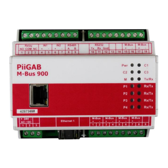
PiiGAB 900’s MAC-address and serial number On the right gable of the PiiGAB 900 you’ll find a label containing MAC-address and serial number of your PiiGAB 900. You can use these to identify your PiiGAB 900 with PiiGAB M-Bus Setup software. - Page 6 7. When ask to start the web interface for your PiiGAB 900 gateway- press Yes to do so 8. You might need to specify a username and password. If these settings has not been changed, the defaults are: Username: Admin ...
-
Page 7: Change Ip-Address Of Your Piigab 900 Gateway
Change IP-address of your PiiGAB 900 gateway In case you don’t have a network with DHCP you can also address your PiiGAB 900 with a static IP- address. For this you also need to set your computer to a static IP-address. - Page 8 12. Wait for the PiiGAB 900 gateway to reboot 13. Press Next to continue 14. Go back to Find your PiiGAB 900 on your network section and see if you can find your PiiGAB 900 gateway with the IP-address you specified...
-
Page 9: Verify The Piigab 900'S License
Verify the PiiGAB 900’s license You might want to check the PiiGAB 900’s license to see what protocols can be used and how many clients you may use. 1. In the web interface, click on Administration in the left panel 2. -
Page 10: Configure Piigab 900'S Master And Slave Ports
Configure PiiGAB 900’s master and slave ports This section describes how the PiiGAB 900 should be configured for M-Bus, Modbus and M-Bus ASCII. Master port 1. In the web interface, click on Configuration in the left panel 2. Click on Master Port and configure it with these settings Slave port 1 (M-Bus communication) 1. -
Page 11: Slave Port 2 (Modbus Communication)
2. Click on Slave Port 3 and configure it with these settings for M-Bus ASCII communication. Note: You can ignore this section if you don’t have a PiiGAB 900 licensed for M-Bus ASCII. If you don’t have a PiiGAB 900 configured for four clients, you can use slave port 1 or slave port 2 instead. -
Page 12: Piigab M-Bus Setup Wizard - M-Bus Communication
PiiGAB M-Bus Setup Wizard – M-Bus communication This section will use PiiGAB M-Bus Setup Wizard to verify if the PiiGAB 900 and RELAY PadPulse M2 responses over M-Bus communication. 1. In the main menu select Test, search and configure meters 2. -
Page 13: M-Bus Communication With Piigab 900 Gateway
M-Bus communication with PiiGAB 900 gateway PiiGAB 900 gateway contains of an internal M-Bus meter which can be used to read the M-Bus voltage and M-Bus current on the M-Bus loop. This test will read from the internal M-Bus meter. -
Page 14: Read M-Bus Voltage And M-Bus Current From Piigab 900
1. Configure these options as seen in the picture below 2. Press the Read button Besides providing the user with the raw data package of the M-Bus response from the PiiGAB 900 gateway, the M-Bus voltage and M-Bus current are displayed. -
Page 15: M-Bus Communication With Relay Padpulse M2
By default, according to EN13757, both M-Bus connections have primary address set to 0. The image above displays the search window in PiiGAB M-Bus Setup Wizard. You can use it to search M- bus meters on the M-Bus loop. -
Page 16: Change Primary Address Of Padpulse M2
Change primary address of PadPulse M2 To start communicating with both pulse meter, one of them must have their primary address changed. When changing the primary address on one of the pulse meter, the other one will remain on primary address 0. -
Page 17: Read Both Primary And Secondary Address From Relay Padpulsem2
The picture above shows that one of the pulse meter now has 1 as primary address. Read both primary and secondary address from RELAY PadPulseM2 1. Configure PiiGAB M-Bus Setup Wizard as one of the images under 2. Press the Find button to test primary address 0 or 1 3. -
Page 18: Piigab Explorer / M-Bus Opc-Server - M-Bus Communication
When the M-Bus communication is confirmed with PiiGAB M-Bus Setup Wizard, you may use PiiGAB Explorer to see what is possible to read from the PiiGAB 900 gateway and RELAY’s PadPulse M2. You can also use PiiGAB Explorer’s built in OPC-client to read the values from the internal meter in the PiiGAB 900 gateway as well as the information in RELAY’s PadPulse M2. -
Page 19: Piigab 900'S Internal Meter
PiiGAB 900’s internal meter PiiGAB 900’s internal meter can be used to retrieve the identification (serial number), M-Bus voltage, M- Bus current and also error status information. Monitor the internal meter 1. Click the Internal node in PiiGAB Explorers tree structure 2. -
Page 20: Data Inside The Internal Meter
Modbus registers can only be altered from this point. They will not affect the other meters’ Modbus registers. But if not correctly configured the Modbus register may overlap each other. Please see the Modbus register list function in PiiGAB Explorer to verify Modbus register don’t overlap if you change them. -
Page 21: Relay's Padpulse M2
PadPulse M2’s manual. The configuration in PiiGAB Explorer for the PadPulse M2 is the most default and generic as possible. The two accumulators in the PadPulse M2 are represented as Value in PiiGAB Explorer. -
Page 22: Data Inside Padpulse M2
Modbus registers can only be altered from these two meters. They will not affect the other meters’ Modbus registers. But if not correctly configured the Modbus register may overlap each other. Please see the Modbus register list function in PiiGAB Explorer to verify Modbus register don’t overlap if you change them. -
Page 23: Piigab M-Bus Setup Wizard - Modbus Communication
If your PiiGAB 900’s license doesn’t have Modbus you can ignore this section. This section let you check the Modbus configuration for a PiiGAB 900. In PiiGAB M-Bus Setup Wizard the Modbus client is a generic client and should work as any other Modbus client. The Modbus client is also an efficient way to check the Modbus configuration before connecting to the actual client. -
Page 24: Piigab 900'S Internal Meter Over Modbus
2. Browse and open PiiGABStartKit3 Wizard Modbus PiiGAB 900.csv file from the local folder 3. Press the Read button to test communication with the PiiGAB 900 gateway over Modbus This will read the internal meter in PiiGAB 900 over Modbus through Slave port 2. -
Page 25: Piigab 900'S Internal Meter Over Modbus With String Data Types
2. Browse and open PiiGABStartKit3 Wizard Modbus PiiGAB 900 ASCII.csv file from the local folder 3. Press the Read button to test communication with the PiiGAB 900 gateway over Modbus This will read the internal meter in PiiGAB 900 over Modbus through slave port 2 as strings. -
Page 26: Relay's Padpulse M2 Over Modbus
2. Browse and open PiiGABStartKit3 Wizard Modbus PadPulse M2.csv file from the local folder 3. Press the Read button to test communication with the PiiGAB 900 gateway over Modbus This will read REALY’s PadPulse M2 meters over Modbus through slave port 2. -
Page 27: Piigab M-Bus Setup Wizard - M-Bus Ascii Communication
1 or slave port 2. This section let you check the M-Bus ASCII configuration for a PiiGAB 900. The M-Bus ASCII client is an efficient way to check the M-Bus ASCII configuration before connecting to the actual client. -
Page 28: Piigab 900'S Internal Meter Over M-Bus Ascii
4. Select PiiGAB 900.Internal.ID (ASCII) from the Tag name drop-down list 5. Press the Read button to test communication with the PiiGAB 900 gateway over M-Bus ASCII This will read the internal meter in PiiGAB 900 over M-Bus ASCII through slave port 3. -
Page 29: M-Bus-Ascii Tag File
3. Browse and open PiiGABStartKit3 Wizard M-Bus ASCII.csv file from the local folder 4. Select PiiGAB 900.PadPulse M2 P1.Value (ASCII) from the Tag name drop-down list 5. Press the Read button to test communication with the PiiGAB 900 gateway over M-Bus ASCII...
Need help?
Do you have a question about the M-Bus 900 and is the answer not in the manual?
Questions and answers