Advertisement
Table of Contents
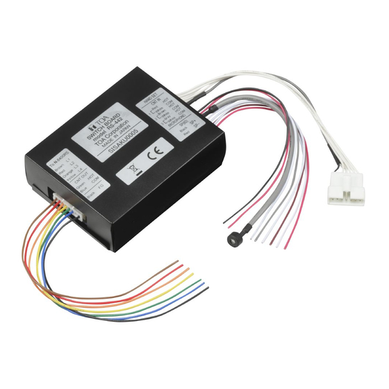
SWITCH BOARD
Thank you for purchasing TOA's Switch Board.
Please carefully follow the instructions in this manual to ensure long, trouble-free use of your equipment.
1. GENERAL DESCRIPTION
The RS-442 is a Switch board to be connected to the N-8400RS 4-wire system Substation Interface Unit.
It is equipped with 1 microphone input (with a microphone unit), 3 switch inputs for call buttons, and 1 speaker
output, enabling you to make a switch panel suitable for applications.
By assigning a different master station as a calling destination to each Call button, you can call one of them
and make a conversation.
Warning
This is a class A product. In a domestic environment this product may cause radio interference in which case
the user may be required to take adequate measures.
2. CONNECTION
N-8400RS Substation interface unit
(supplied with the N-8400RS)
Two pairs of
twisted pair cable
[RS-442 and RS-481 connections]
Handset cables
RS-481
4P removable terminal plug
To line 1 (Brown)
To line 2 (Red)
To line 3 (Orange)
To line 4 (Yellow)
Control output *
(Green)
(Blue)
(Black)
Diode
Frame
ground
Relay
-
*Open collector output: 24 V DC, Max. 30 mA
Wall surface
Handset joint
cables
RS-442
Installation MANUAL
Note
Cut out unused wires to avoid short-circuiting.
RS-442
External
power supply
+
24 V DC
GND
Note
When using the RS-481 Option handset, cut the
jumper wire next to the handset joint cables on
the circuit board as illustrated below.
If not cut, sound comes out from the RS-442's
speaker and returns back to the handset's
microphone, resulting in acoustic feedback.
RS-442 (Bottom)
RS-442
To handset
(refer to the following figure)
+
(Red)
8 Ω speaker output
-
(Black)
Microphone
(White)
Switch input for
the call button 3
(Gray)
(momentary)
(White)
Switch input for
the call button 2
(Brown)
(momentary)
(White)
Switch input for
the call button 1
(Blue)
(momentary)
Jumper wire
Handset joint cables
Advertisement
Table of Contents

Subscribe to Our Youtube Channel
Related Manuals for Toa RS-442

Summary of Contents for Toa RS-442
- Page 1 Wall surface jumper wire next to the handset joint cables on the circuit board as illustrated below. If not cut, sound comes out from the RS-442's speaker and returns back to the handset's microphone, resulting in acoustic feedback. RS-442 (Bottom)
- Page 2 3. INSTALLATION 3.1. Installation Completion Drawing Unit: mm [Front] [Side] [Rear] 28.1 67.5 3.2. When Making Operation Panel for Flush-Mount Installation Put the RS-442 in the YC-302 2-Gang Electrical Box mounted in the wall. Then, connect the cables from RS-442 to the switches mounted on the operation panel separately prepared. Wall surface YC-302 2-Gang Electrical Box YC-822 Indoor Wall-Mount Box (option) can also be used. RS-442 Operation panel (separately prepared) Note: When using the PA paging function, keep the operation panel as far away from the PA paging speaker as possible to avoid acoustic feedback.
Need help?
Do you have a question about the RS-442 and is the answer not in the manual?
Questions and answers