Table of Contents
Advertisement
Available languages
Available languages
Quick Links
Advertisement
Table of Contents

Subscribe to Our Youtube Channel
Related Manuals for Nakayama Pro PS2605


Summary of Contents for Nakayama Pro PS2605
- Page 1 PS2605 036487 ART NO: WWW.NAKAYAMATOOLS.COM...
- Page 2 WWW.NAKAYAMATOOLS.COM...
- Page 3 WWW.NAKAYAMATOOLS.COM...
- Page 4 ζ ζ2 χ ζ3 0.6 - 0.9mm ζ4 υ WWW.NAKAYAMATOOLS.COM...
- Page 5 ζ5 ζ20 ζ17 ζ21 ζ18 ζ19 ζ22 WWW.NAKAYAMATOOLS.COM...
-
Page 6: General Safety Instructions
General safety instructions This machine can cause serious injuries. Read the instructions carefully for the correct handling, preparations, maintenance, starting and stopping of the ma- chine. Be familiar with all controls and the proper use of the machine. Keep this manual handy so that you may refer to it later whenever any questions arise. Also note, if you have any questions which cannot be answered herein, contact the dealer from whom you purchased the product. - Page 7 •Under no circumstances should you ever take apart the product or alter it in any way. Doing so might result in the product becoming damaged during opera- tion or the product becoming unable to operate properly. Handling fuel •The engine is designed to run on a mixed fuel, which contains highly flammable gasoline. Never store cans of fuel or refill the tank of the unit in any place where there is a boiler, stove, wood fire, electrical sparks, welding sparks, or any other source of heat or fire which might ignite the fuel.
- Page 8 Assembly instructions and main adjustments Mounting the engine (A) 1. Push the shaft tube toward the clutch housing and rotate it by hand to check that the drive shaft is en gaged with the gears. 2. Insert the shaft tube into the clutch housing until it bottoms, and align the positioning holes on the clutch housing and the shaft tube and install the screw. When difficult to engage, twist the engine slightly.
-
Page 9: Fuel And Chain Oil
3. In order to prevent the hanger position to change during operation, turn up the extra part of the band from the buckle. Quick Release The harness is equipped with a “quick release”devise. To release the machine from the harness in emergency situations, please follow the procedure as explained below. Warning: Make sure to check proper working of the quick release device before operating the machine. - Page 10 2. Put fuel into the fuel tank to 80% of the full capacity. 3. Fasten the fuel cap securely and wipe up any fuel spillage around the unit. Operation (P) (1) Stop switch 5. Set the stop switch to the ‘‘ - ‘‘position. Set the throttle trigger to the start position (1 - 2 - 3). Place the unit on a flat, firm place.
-
Page 11: Maintenance
Maintenance Every Every 25 Every 50 Before System/components Procedure hours hours Note hours after after after Fuel licks, fuel spillage Wipe out Fuel tank, air filter, fuel filter Inspect/clean Replace if necessary Idle adjusting screw See adjusting Replace carburetor if ... -
Page 12: Troubleshooting
(2) Intake air cooling vent (back) Procedures to be performed after every 100 hours of use 1. Remove the muffler, insert a screwdriver into the vent, and wipe away any carbon build-up. Wipe away any carbon build-up on the muffler exhaust vent and cylin der exhaust port at the same time. -
Page 13: Οδηγίες Ασφαλείας
Οδηγίες ασφαλείας Αυτό το εργαλείο μπορεί να προκαλέσει σοβαρά τραύματα. Διαβάστε προσεκτικά τις οδηγίες για τον σωστό χειρισμό, την προετοιμασία, τη συντήρηση, την εκκίνηση και τη διακοπή λειτουργίας του εργαλείου. Βεβαιωθείτε πως έχετε εξοικειωθεί με την τρόπο λειτουργίας των χειριστηρίων και με τη σωστή χρήση του... - Page 14 τε λόγω του θορύβου του εργαλείου. •Ποτέ μην χειρίζεστε το εργαλείο σε γωνία μεγαλύτερη των 60 ° ώστε να μειωθεί ο κίνδυνος τραυματισμού από πτώση αντικειμένων κατά τη διάρκεια της λειτουργίας. •Αποφύγετε τη λειτουργία ενώ βρίσκονται κοντά σας άλλα άτομα και ιδιαίτερα τα παιδιά. Συντήρηση...
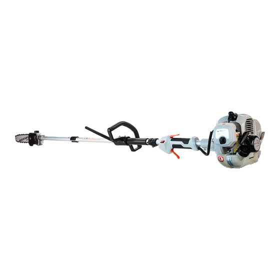
- Page 15 Περιγραφή βασικών τμημάτων και εξαρτημάτων Τεχνικά χαρακτηριστικά 1. Εξάτμιση 2. Ντίζα τροφοδοσίας (γκαζιού) PS2605 Μοντέλο 3. Διακόπτης ON/OFF Κυβισμός: 25.4cc 4. Εμπρόσθια χειρολαβή 5. Ταχυσύνδεσμος (σύνδεσμος μπαστουνιού) Ιπποδύναμη: 6. Κοντάρι (Μπαστούνι) Μήκος λάμας: 25cm 7. Σημείο σύνδεσης εξάρτυσης 8. Σκανδάλη τροφοδοσίας (γκαζιού) Τύπος...
- Page 16 αμφότερα να ταιριάζουν στα άκρα τους. H κεφαλή/κάτω σωλήνας θα πρέπει να έχουν προσανατολισμό προς τα άνω, και το άνω τμήμα θα πρέπει να τοπο- θετείται με την προστασία μανδάλωσης (Latch) με προσανατολισμό προς τα άνω. 2. Ξεβιδώστε την βίδα 3.
- Page 17 4. Ρυθμίστε την τάση της αλυσίδας περιστρέφοντας τη βίδα του ρεγουλατόρου έως ότου οι κρίκοι της αλυσίδας να αγγίξουν την κάτω πλευρά της λάμας και ανασηκώνοντας την με το χέρι να δημιουργείται ένα μικρό κενό (N). (1) Βίδα ρύθμισης τάσης αλυσίδας (a) Χαλαρώστε...
- Page 18 (1) Καύσιμο (2) Αλυσίδα (1) Βίδα ρύθμισης του ρελαντί 1. Πιέστε την φούσκα αρκετές φορές έως ότου βγει καύσιμο υπερχείλισης στον διάφανο σωλήνα. 2. Μετακινήστε το μοχλό του τσόκ στην κλειστή θέση | \ |. 3. Σε περίπτωση που η λειτουργία του κινητήρα διακόπτεται σε κατάσταση ρελαντί (σβήνει), γυρίστε τη βίδα ρύθμισης δεξιόστροφα. 4.
- Page 19 Συντήρηση Πρίν Κάθε 25Ω Κάθε 50Ω Κάθε 100Ω Μηχανισμός/εξαρτήμα Διαδικασία απο την Σημείωση λειτουργίας λειτουργίας λειτουργίας χρήση διαρροή καυσίμου Καθαρισμός Δεξαμενή καυσίμου, φίλτρο αέρα, Έλεγχος/καθαρισμός Αντικαταστήστε εφόσον φίλτρο καυσίμου χρειάζεται Βίδα ρύθμισης ρελαντί Βλέπε ρύθμιση του Αντικαταστήστε το ρελαντί...
- Page 20 μπορέσετε να δείτε το πάνω μέρος του κυλίνδρου. Σημαντικό: Εάν τα υπολείμματα κολλήσουν και φράξουν τον αεραγωγό εισαγωγής αέρα ή μεταξύ των πτερυγίων του κυλίνδρου, μπορεί να προκαλέσει υπερθέρμανση του κινητήρα και αυτό με τη σειρά του μπορεί να προκαλέσει μηχανική βλάβη στο μηχάνημα. (1) Κύλινδρος...
Need help?
Do you have a question about the Pro PS2605 and is the answer not in the manual?
Questions and answers