
Related Manuals for Finn T30 HydroSeeder SD


Summary of Contents for Finn T30 HydroSeeder SD
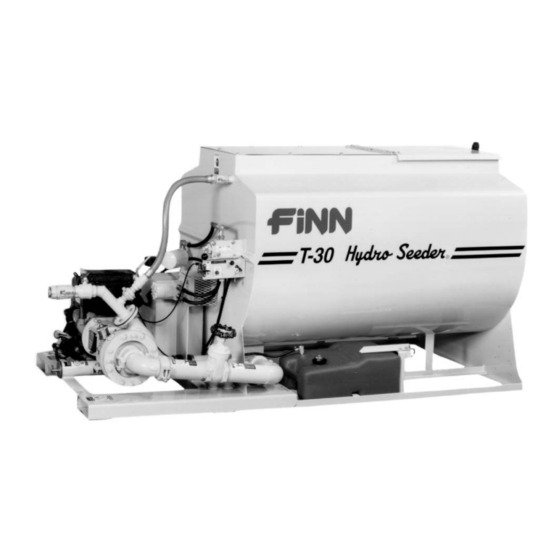
- Page 1 9281 LeSaint Drive • Fairfield, Ohio 45014 Phone (513) 874-2818 • Fax (513) 874-2914 ® T30 HydroSeeder Parts and Operator’s Manual Model SD Serial No. LBT30-SD Rev C...
- Page 3 ▪ Return the part(s) and the completed Warranty Claim Form to Finn Corporation using the return shipping label. (Within 2 weeks) ▪ Tape the Orange identifier sheet, marked with the W / RMA# on the outside of the box you are shipping the defective part(s) to Finn in.
- Page 4 (except those referred to herein) that are manufac- dealers, or any other party. tured by Finn to be free from defects in material and workmanship 5. This Warranty does NOT cover any costs associated with trans- for a period of 12 months from date of purchase or 1200 hours of use, whichever comes first.
-
Page 5: Table Of Contents
Agitator and Bearing Assembly......36-37 Continued . . . ® Hydroseeder is a registered trademark of the Finn Corporation... - Page 6 INDEX CONTINUED Common Loose Parts & Engine......38-39 Control Panel Wiring ........40 Tool Kit .
-
Page 7: Safety First
SAFETY FIRST With any piece of equipment, new or used, the most important part of its operation is SAFETY! Finn Corporation encourages you and your employees to familiarize yourselves with your new equipment and to stress safe operation. The first six pages of this manual are a summary of all the main safety aspects associated with this unit. -
Page 8: Safety Summary Section
The FINN HydroSeeder ® is designed to mix and apply water, seed, fertilizer, agricultural lime and hydraulic mulch to the prepared seedbed. The resultant slurry from mixing one or more of the above materials may react causing harmful or deadly gasses within the tank. - Page 9 4. Make sure area to be sprayed is clear of all persons, direct hose may be necessary if working on slopes. animals, etc. The proper technique for hose holding personnel is to firmly grasp the hose over the shoulder or under 5.
- Page 10 Do NOT 8. It is recommended that only authorized genuine allow material to come in FINN replacement parts be used on the machine. contact with personnel. Severe bodily injury could 9. Diesel fuel or hydraulic fluid under pressure can result.
- Page 11 CURRENT SET OF SAFETY DECALS DA NG E R Before entering the tank: 1. Drain, flush and ventilate tank interior. 2. Turn off engine and disconnect battery cables. B U R N H A Z A R D ! 3. Provide continuous ventilation DO NOT c ome in or proper breathing apparatus.
-
Page 12: Definition Of Hydroseeding
FINN T30 HYDROSEEDER This manual gives you step by step instructions for the operation and maintenance of the Finn HydroSeeder ® . For best results and to insure longer life of the equipment, please follow the instructions carefully. For your safety read the entire manual before operation of this unit. -
Page 13: Mounting
Mounting the HydroSeeder ® to the truck must allow for tire IMPORTANT: clearance as well as frame twist. Place hard wood spacers along the length of truck rails or use Finn spring mounting kit (#011562) or equivalent. IMPORTANT: When using a truck with a tilt bed be sure to chain the truck bed down to prevent the bed from being accidentally hoisted. -
Page 14: Pre Start Check
Turn thumb nut clockwise until stem rises to maximum height. b) Remove cap and fill cap with sodium (water soluble) base grease. (FINN part number 000698). Do not use lithium base (chassis lube) grease. c) Replace cap. -
Page 15: Valve Operation
10. Check and clean the nozzles and hoses of any obstructions. 11. Check pump discharge, recirculation, and remote valve handles for free movement. VALVE OPERATION: The base HydroSeeder ® is equipped with three (3) independently operated ball valves to control slurry flow (see Fig. -
Page 16: Starting Procedure
The following tables show loading versus coverage rates for the Finn T30. Table A shows rates for “one step” applications. The coverage area is determined by the fiber mulch capacity of the HydroSeeder ® , and the rate at which it is applied. - Page 17 TABLE A USING SEED, FERTILIzER AND MULCH Unit Amount of Material in Tank (pounds(kilograms)) Covrage Area Seed Fertilizer Mulch Sq. Ft. (Sq. m.) 28 lbs (13 kg) 32 lbs (15 kg) 120 lbs (54 kg) 3,485 (324) Above Table is based on 1,500 pounds of mulch, 400 pounds of fertilizer and 345 pounds of seed (8 pounds/1,000 square feet) per acre.
-
Page 18: Tank Capacity Chart
TANK CAPACITY CHART: BOTTOM FIGURE 3 T-30 Gallons in. (cm) from in. (cm) from (liters) bottom (1136) 6.25 (15.9) 32.75 (83.2) (1041) 8.75 (22.2) 30.25 (76.8) (946) (27.9) (71.1) (852) 13.5 (34.3) 25.5 (64.8) (757) (40.6) (58.4) (662) 18.25 (46.4) 20.75 (52.7) (568) -
Page 19: Loading
LOADING: CAUTION: Take care not to lose pens, lighters, etc. from shirt pockets or drop pieces of paper or plastic bags into the tank, as these might plug the slurry system. 1. With clutch disengaged (off) and agitator control in the neutral position, start engine and allow it to warm up (See "Starting Procedure"... -
Page 20: Prior To Application
CAUTION: Hydraulic system will overheat if agitator shaft is jammed for extended period. This will damage hydraulic oil and system components. C. Fertilizer - Cut the fertilizer bag and dump the contents into the slurry tank. D. All other additives - Consult with manufacturer for proper loading technique. 7. -
Page 21: Application Of Slurry
APPLICATION OF SLURRY: I. GENERAL APPLICATION TECHNIQUES DANGER: Do not spray toward power lines, transformers or other high voltage conductors. CAUTION: The driver of the carrying vehicle should remain alert for hazards to the operator, such as low power lines, hanging branches, etc. -
Page 22: Reloading
3. With the engine at ¾ speed, open the remote valve at the end of the hose to discharge the load. 4. When finished spraying, close the remote valve, disengage (turn off) the clutch, and stop the engine. If using fiber mulch, retain as much water as possible in the hose by elevating the ends or by cou- pling the ends together. -
Page 23: Hydraulic System
The hydraulic oil filter must be replaced on schedule with a 25 absolute micron filter - Finn part #021618. The hydraulic system relief is factory set... -
Page 24: Lubrication Chart
LUBRICATION AND FLUIDS CHART Ref. No. Location Lubricant Frequency Number Check Grease Level in Pressure Lubricator Daily Grease Agitator Shaft Bearings Daily Check Engine Oil Level Daily Change Engine Oil and Filter See Engine Manual Grease Pump Bearings Weekly Check Hydraulic Fluid Level Weekly Change Hydraulic Fluid and Filter Seasonally... -
Page 25: Pump Maintenance
Suction Cover Bolt Clutch Retainer Suction Cover Washer 8 Locking Bolt Radial Lip Seal Lock Washer Casing Bearing Clutch Bearing Bolt Clutch Spacer Bearing Washer Pump Frame Frame Bearing Casing Drain Plug NOTE: See parts manual for Finn part number... - Page 26 A. FACTORY-TOLERANCES 1. To check pump tolerances loosen the two clamps on the pump suction piping and remove the inlet elbow. Through the pump suction hole, insert a feeler gauge between the pump impeller (3) and the suction cover (1). This measurement on a new pump is 0.030-0.045 inches (0.762 -1.15 mm). B.
-
Page 27: Trouble Shooting The Hydroseeder
D. INSTALLING NEW SEAL ASSEMBLY (#4) (DO NOT UNWRAP THE NEW SEAL ASSEMBLY UNTIL YOU ARE READY TO INSTALL. ALL PARTS OF THE ASSEMBLY ARE PACKED IN SEQUENCE OF INSTALLATION.) 1. To replace the seal assembly (4), perform the above operations under cleaning and remove pump casing (5) by removing the four bolts (7B) holding the casing and the casing bearing (7) to the pump frame (15). - Page 28 Sometimes when a stoppage occurs, you will not be able to find anything in the line. When this happens, it means the system became airbound instead of plugged. To remedy this, see “Foaming”. Plugging can occur in any 1 of 4 places; the valve and recirculation nozzle, the discharge nozzle, the pump area and the sump area.
- Page 29 ® TROUBLE SHOOTING YOUR HYDROSEEDER Problem Probable Causes Suggested Solutions LEAKS: Tank bearing Lack of lubrication - Replace seal and follow lube leaks. seal worn. Schedule. Bolts not tightened Tighten uniformly to 25 ft. lbs. properly. Pressure Clamps. Rubber seal cracked, Replace, always grease seal pinched or torn.
- Page 30 ® TROUBLE SHOOTING YOUR HYDROSEEDER Problem Probable Causes Suggested Solutions MACHINE JUMPS DURING OPERATION: Agitator. Agitator bent by heavy Straighten agitator or shim, so it object falling on it. runs true. Bent Paddles. Loading fiber mulch Straighten agitator paddle, realign into tank before tank is agitator to run true.
- Page 31 ® TROUBLE SHOOTING YOUR HYDROSEEDER Problem Probable Causes Suggested Solutions Constant plugging Incorrect loading procedure. Review loading procedure, pages during loading and 13-14. discharging. Improper operation by Reinstruct your operator. (Review operator. Operator’s Manual). Not moving valve handle Valve should be fully open. far enough.
- Page 32 NOTES...
-
Page 33: Parts Section
Hydroseeder ® Parts Manual Model SD... - Page 34 WHEN ORDERING PARTS, BE SURE TO STATE SERIAL NUMBER OF MACHINE...
-
Page 35: Suction, Discharge, And Recirculation
SUCTION, DISCHARGE AND RECIRCULATION PIPING Ref. No. Part Number Description No. Req'd 085160 Clump Assembly (See Pages 30-31 for parts breakdown) 080366 Pipe Clamp 002439 Clamp Gasket 1 per 002868 90° Grooved Elbow 085210 Suction Pipe Weldment 008469 Discharge Flange Gasket 080558-01 Discharge Flange Pipe 005083-07... - Page 36 WHEN ORDERING PARTS, BE SURE TO STATE SERIAL NUMBER OF MACHINE...
-
Page 37: Clump Assembly
CLUMP ASSEMBLY Ref. No Part Number Description No. Req'd 085160 Clump Assembly 080489 Suction Cover 0X0720 Suction Cover Bolt 000Y07 Suction Cover Nut 080499 O-Ring 085159 Impeller 080485 Mechanical Seal 080487 Pump Casing 0X0720 Suction Cover Bolt 000W07 Suction Cover Washer 080493 Radial Lip Seal 080498... - Page 38 WHEN ORDERING PARTS, BE SURE TO STATE SERIAL NUMBER OF MACHINE...
-
Page 39: Hydraulic System
HYDRAULIC SYSTEM Ref. No. Part Number Description No. Req'd 085140 Filler Breather Cap 004618 Suction Strainer 023186 Nipple 020658 Ball Valve 023616 Straight Male Adapter 085153 Suction Hose 085157 45° Male Adapter 080642 Hydraulic Pump 055309 Male 90° Adapter Elbow 085156 Pressure Hose FW71451... -
Page 40: Hydraulic Pump Drive Assembly
HYDRAULIC PUMP DRIVE ASSEMBLY Ref. No. Part Number Description No. Req'd 0X0616 3/8-16 x 1" Lg. Hex Hd. Bolt 080642 Hydraulic Pump F30-0001 Hydraulic Pump Coupling Guard 080647 Coupling Half 5/8" Bore 080324 Coupling Insert 085023 Coupling Half 1" Bore 190123-24 1/4"... -
Page 41: Hydraulic Agitator Drive Assembly
HYDRAULIC AGITATOR DRIVE ASSEMBLY Ref. No. Part Number Description No. Req'd 0X0824 1/2-13 x 1-1/2" Lg. Hex Hd. Cap Screw 080482 Hydraulic Motor F60-0022-02 Agitator Coupling Guard 00Y08L 1/2-13 Locknut 085128-01 Torque Arrestor Plate 080523 2-Piece Rigid Coupling Assembly 080582 Worm Gear Clamp 085150 Rubber Torque Arrestor Pad... - Page 42 BEARING ASSEMBLY NOTE: To tighten, Turn nut not bolt. Torque to 25 Ft. Lbs. 1-1/2" Agitator DO NOT OVER TORQUE Shaft Through Back Side NOTE: 085161-01 Rear Bearing Assembly 085161-02 Front Bearing Assembly (both include items #1 - 9) Outside Of Tank Wall AGITATOR ASSEMBLY...
-
Page 43: Agitator And Bearing Assembly
AGITATOR AND BEARING ASSEMBLY Ref. No. Part Number Description No. Req'd 085161-01 Rear Bearing Assembly (Includes #1 thru #9) 085161-02 Front Bearing Assembly (Includes #1 thru #9) 085162-01 Rear Clamping Ring 1 per 085162-02 Rear Clamping Ring 1 per 007416 Shaft Seal 1 per 006975... - Page 44 WHEN ORDERING PARTS, BE SURE TO STATE SERIAL NUMBER OF MACHINE...
- Page 45 COMMON LOOSE PARTS & ENGINE Ref. No. Part Number Description No. Req'd 035127 Battery 085212 Black Battery Ground Cable 085213 Red Battery Power Cable 005161 Battery Holddown Strap 085145 Hydraulic Reservoir F30-0001 Hydraulic Pump Coupling Guard 004593 Drain Plug 085139 Fuel Tank 085132-02 Fuel Tank Lever Arm...
- Page 46 IGNITION CLUTCH SWITCH SWITCH WHITE CLUTCH ENGINE PLUG CONTROL PANEL WIRING Part Number Description No. Req'd 080654 Ignition Switch 010531 Clutch Toggle Switch 080526 Clutch Toggle Switch Dust Boot 035084 Electric Clutch 085128-02 Control Panel WHEN ORDERING PARTS, BE SURE TO STATE SERIAL NUMBER OF MACHINE...
- Page 47 Narrow Ribbon Nozzle 080260 Nyglass Adapter 160750 Reducer Bushing 004593 Drain Plug 006515 Coupler Gasket 012681T Finn Beige Touch-Up Paint 012681A Finn Beige Aerosol Paint 080535 Remote Valve Assembly 012083 Full Port Ball Valve 080260 Male Nyglass Adapter 080261 Female Nyglass Coupler...
- Page 48 Hydro Seeder WHEN ORDERING PARTS, BE SURE TO STATE SERIAL NUMBER OF MACHINE...
- Page 49 023519 Decal "CAUTION! Wear Eye Protection..." 008097 Decal "DANGER! Do Not Enter Tank" 085078 Decal "Operating Instructions" 007535 Decal "Throttle" 012260 FINN Maintain Decal Plate 085137 Decal "Pump On/Off" 020976 Decal "Patent Infringement" 008286 Decal "Agitator Speed" 031331 Decal "Gasoline"...
Need help?
Do you have a question about the T30 HydroSeeder SD and is the answer not in the manual?
Questions and answers