Table of Contents
Advertisement
Quick Links
Advertisement
Table of Contents

Summary of Contents for Ametek CAN-Communicator
- Page 1 SPARTAN CHASSIS LIGHTBAR MESSAGE CENTER USER GUIDE 072-101929...
-
Page 2: Table Of Contents
Table of Contents DESCRIPTION ........................4 SPECIFICATIONS ......................5 SCREEN MENU OVERVIEW ..................10 SCREEN MENU DETAIL ....................11 POWER UP ......................... 11 DATA .......................... 12 MAIN MENU - OVERVIEW ..................14 MAIN MENU - WARNINGS ..................15 MAIN MENU – WARNINGS ..................16 POP UP MESSAGES .................... - Page 3 However, no guarantee is given or implied that the document is error-free or that is accurate with regard to any specification. AMETEK VIS reserves the right to modify product designs and specifications without notice.
-
Page 4: Description
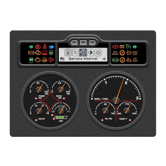
DESCRIPTION The CAN-Communicator (C-COM) Lightbar Message Center (LMC) combines the advantages of a graphic display with a 28-telltale lightbar. This rugged and versatile message center can be used exclusively, or as a compliment, to any existing instrumentation simply by connecting it to an SAE J1939 (CAN) data bus. -
Page 5: Specifications
SPECIFICATIONS Physical Characteristics Housing and bezel material: Black polycarbonate ABS plastic Connector: 34-pin AMP superseal, polarized and locking Environmental Characteristics Temperature, humidity, shock, vibration, and salt spray: Meets or exceeds SAE #J1455-1994-08 Operating Temperature: -40 to +85 Electrical Characteristics Operating limits: 9 to 32 VDC, reverse polarity protected Transient protection: Meets or exceeds SAE #J1455-1994-08 Electrical Inputs Battery/ignition: 9 to 32 volts... - Page 6 Electrical Connections Mating Connector Amp 4-1437290-0 Cluster's Input Name Customer's Function Channel Configuration Battery Battery +12 V Input Ground Ground Chassis Ground Ignition Ignition +12 V Input J1939 (+) J1939 (+) J1939 (+) J1939 (-) J1939 (-) J1939 (-) ABS or STG Not Used Not Used General Purpose 7...
- Page 7 Gauge Dimensions Panel Cut-Out Dimensions Page 7 of 45 072-101929...
- Page 8 Lightbar Telltale Icons Telltale LMC's Input Description Color Alarm Location Name Not Used Not Used Left Turn Left Turn Green No Alarm ABS System J1939 Databus Amber No Alarm Fault Automatic Traction Control J1939 Databus Green No Alarm Lamp Stop Engine J1939 Databus No Alarm Check Engine...
- Page 9 Telltale LMC's Input Description Color Alarm Location Name Cruise Control J1939 Databus Green No Alarm Enabled Diesel Particulate J1939 Databus Amber No Alarm Filter (DPF) High Exhaust System J1939 Databus Amber No Alarm Temperature (HEST) Right Turn Right Turn Green No Alarm Cargo Door Ajar Cargo Door Ajar...
-
Page 10: Screen Menu Overview
SCREEN MENU OVERVIEW START UP SCREEN DATA SCREEN MAIN MENU WARNINGS DIAGNOSTICS SELF TEST SETUP Page 10 of 45 072-101929... -
Page 11: Screen Menu Detail
SCREEN MENU DETAIL POWER UP Screen Blank for 3 seconds Logo displayed for 3 seconds DATA SCREEN 1. When power is first applied to C-COM LMC, the display will turn on all pixels for three seconds. 2. The SPARTAN logo will then be displayed for three seconds. 3. -
Page 12: Data
DATA 73.1 M Trip 1 73.1 M 73.1 M Trip 2 25.3 M 73.1 M Trans Temp 300 F 73.1 M Air Temp 150 F Fuel Ave 12 MPG Fuel Inst 10 MPG Fuel Left 105 M Cruise Spd 3000 70 MPH 1950 Heading... - Page 13 Pressing any button while on a data screen will enable movement from that data screen and activate icons that indicate what each button press will do. After 5 seconds without further button press, movement from that data screen will be disabled and the movement icons will go away.
-
Page 14: Main Menu - Overview
MAIN MENU - OVERVIEW DATA SCREEN Warnings Screens Diagnostic Screens Self Test Screens Setup Screens Press the Right button to scroll through the Main Menu – Warnings, Diagnostics, Self Test, and Setup. The item will be highlighted as it’s selected. Press the Center button to access that selection. -
Page 15: Main Menu - Warnings
MAIN MENU - WARNINGS MAIN MENU - Warnings Selected # / # Remainder of Warnings With the Warnings selected from the Main Menu, press the Center button to view the warnings. Press the Right button, corresponding to the right arrow prompt on the display, to view each warning message in the list. -
Page 16: Main Menu - Warnings
MAIN MENU – WARNINGS POP UP MESSAGES Check LMC's Internal External Message LMC's Input Name Acknowledgeable Message Buzzer Alarm Output PARK BRAKE ON - Steady Tone J1939 Databus TRANS NOT IN NEUTRAL TRANS IN NEUTRAL - Steady Tone J1939 Databus PARK BRAKE NOT SET SEAT BELT WARNING Chime... - Page 17 Check LMC's Internal External Message LMC's Input Name Acknowledgeable Message Buzzer Alarm Output DPF REGEN REQUIRED - Steady Tone J1939 Databus CRITICAL STABILITY CONTROL J1939 Databus ACTIVE TRACTION CONTROL J1939 Databus ACTIVE NO DATA J1939 Databus NO DATA - ABS J1939 Databus NO DATA - ENGINE J1939 Databus...
-
Page 18: Def Levels
DEF LEVELS Check Stop Audible LED Level Indicator DEF Level Warning Engine Engine LCD Message Engine Inducement Warning Lamp Lamp Lamp 75%-100% None None 50%-75% None None 25%-50% None None 10%-25% None None LOW DIESEL EXHAUST 2.5%-10% Chime (5 sec) None FLUID ENGINE DERATED -... -
Page 19: Main Menu - Diagnostics
MAIN MENU - DIAGNOSTICS MAIN MENU - Diagnostics Selected Active Active Active Faults Screens Stored Stored Faults Screens Once the center button is pressed to view Diagnostics from the Main Screen, Active Faults or Stored Faults can be viewed. Press the Right button to switch between Active and Stored, then the Center button to select. - Page 20 Comment [GG1]: The format of the Fault screen when viewing the details is not exactly correct. Active Diagnostics Menu - Active Faults Selected View # / # Remainder of Sources Source 0 Source x # / # SPN xxx Remainder of Faults FMI xxx Upon selection of Active Faults, the Source ID will be displayed if there are Active Faults from any devices on the vehicle.
- Page 21 Stored Diagnostics Menu - Active Faults Selected View # / # Remainder of Sources Source 0 Source x # / # SPN xxx Remainder of Faults FMI xxx Comment [GG2]: The format when viewing the fault details is not exactly correct. Upon selection of Stored Faults, a message is sent to other devices on the vehicle requesting their stored faults.
-
Page 22: Main Menu - Self Test
MAIN MENU – SELF TEST Main Menu - Self Test Selected Auto Selftest Auto Selftest Digital Outputs Analog Once the Center button is pressed to enter the Self Test menu, there are five options to choose from – Auto Self Test, Digital Inputs, Switched Outputs, Analog Inputs, and Version. -
Page 23: Auto Self Test
MAIN MENU – SELF TEST AUTO SELF TEST Auto Selftest Self Test - Auto Self Test Selected 3 Seconds 3 seconds 3 Seconds With Auto Selftest, the screens will scroll through automatically at 3 second intervals. If there are NGI gauges connected to the C-COM LMC they will self-test through min, mid and max sweep levels. -
Page 24: Digital Inputs
MAIN MENU – SELF TEST DIGITAL INPUTS Digital Self Test - Digital Inputs Selected Right Button Next Input In the Self Test Digital Inputs menu, each digital input can be tested. The corresponding connector, pin, and input number are displayed, as well as a real time 20 second snap shot of the activation level. -
Page 25: Switched Outputs
MAIN MENU – SELF TEST SWITCHED OUTPUTS Outputs Self Test - Switched Outputs Selected SW Out 1- J1:19 SW Out 2- J1:18 Open/Close Switch SW Out 1- J1:19 SW Out 2- J1:18 Open/Close Switch In the Self Test Switched Outputs screen, the Output switch can be open or closed. -
Page 26: Analog Inputs
MAIN MENU – SELF TEST ANALOG INPUTS Analog Self Test - Switched Outputs Selected Next Input 1. In the Self Test Analog Inputs screen, each Analog input can be tested. The corresponding connector, pin, and analog number are displayed, as well as a real time 20 second snap shot of the activation level. -
Page 27: Version
MAIN MENU – SELF TEST VERSION Self Test - Version Selected SW VER: 1.0 HW ID: CCOM*LMC CFG ID: 123456A Serial: 1234 1. In the Version screen, the software, hardware and configuration versions are displayed along with the serial number of the unit. 2. -
Page 28: Main Menu - Set Up
MAIN MENU – SET UP OVERVIEW Main Menu - Setup Selected Data Setup Data Setup Screen Units Units Screen Contrast Contrast Screen Brightness Brightness Screen Service Service Screen Compass Compass Screen Once the center button is pressed to enter the Setup Menu, there are six options to choose from –... -
Page 29: Data Setup
MAIN MENU - SETUP DATA SETUP Data Setup Setup - Data Setup Selected Add Screen Setup Screen Remove Remove Screen Setup Screen Edit Edit Screen Setup Scren 1. In Data Setup, screens can be added, removed or edited. To scroll through these selections press the Right button. - Page 30 MAIN MENU - SETUP DATA SETUP ADD SCREEN Format 1 Add Screen - Format 1 Selected Odometer 0.0 Miles Tach ---- RPM Tach ---- RPM Scroll Data Scroll Data 1. When adding a Data screen, there are four formats to choose from. Press the Right button to scroll through the different formats and the Center button to choose the highlighted format.
- Page 31 MAIN MENU - SETUP DATA SETUP REMOVE SCREEN Remove Data Setup - Remove Screen Selected Next Screen Remove? 1. To remove a Data screen, press the Right button to scroll through the currently configured screens. 2. Press the Center button to remove the screen and then a prompt will ask if the screen is to be removed.
- Page 32 MAIN MENU - SETUP DATA SETUP EDIT SCREEN Edit Data Setup - Edit Selected Next Screen Air Pressure Next Section Scroll Data 1. To edit a data screen, press the Right button to scroll through the screens that are available to be edited. Press the Center button to select. 2.
-
Page 33: Units Setup
MAIN MENU - SETUP UNITS SETUP Units Setup - Units Selected English Set Current Units to English Metric Set Current Units to Metric 1. In the Units menu, the units can be set to English or Metric. Press the Right button to change between English and Metric. -
Page 34: Contrast
MAIN MENU – SETUP CONTRAST Contrast Setup - Contrast Selected Decrease Contrast Increase Contrast 1. In the Contrast menu, the display contrast can be changed. Press or hold the Right button to increase the contrast and the Left button to decrease the button. -
Page 35: Brightness
MAIN MENU - SETUP BRIGHTNESS Brightness Setup - Brightness Selected Fixed Accept Current Brightness Increase Decrease Setting Brightness Brightness 1. In the Brightness menu, the Backlight for the display can be adjusted. Press the Right button to choose between Analog and Fixed. 2. -
Page 36: Service
MAIN MENU - SETUP SERVICE Service Setup - Service Alarm Selected Distance Set Interval Screen (Distance) Hours Set Interval Screen (Hours) Disable Service Interval 1. In the Service Alarm menu, the intervals can be changed or disabled. Press the Right button to select by distance, hours or disable the alarm. Page 36 of 45 072-101929... - Page 37 MAIN MENU - SETUP SERVICE DISTANCE Distance Service Alarm - Distance Selected Reset Interval to 3000 Mi? Service Move to Next Display Next Value Digit (0-9) Interval Reset to 3000 Mi. 1. Press the center button to set the distance interval, while this choice is selected. Press the Right button to move to the next digit.
- Page 38 MAIN MENU - SETUP SERVICE HOURS Hours Service Alarm - Hours Selected Reset Interval to 300 Hr? Service Move to Next Display Next Value Digit (0-9) Interval Reset to Interval Not 300 Hr Reset 1. Press the Center button to set the Hours interval, while this choice is selected. Then press the Right button to move to the next digit.
- Page 39 MAIN MENU - SETUP SERVICE DISABLED Disabled Service Alarm - Disabled Selected Disable Interval? Service Interval Not Interval Disabled Disabled 1. Press the Center button to view the Disable Service menu. Press the Left button to return to the Service Alarm menu. 2.
-
Page 40: Compass
MAIN MENU - SETUP COMPASS Compass Setup- Compass Selected Calibrate Calibrate Compass Declination Set Declination on Compass 1. In Compass Setup, the unit can be calibrated and the declination set. To scroll through the sections, press the Right button. To select the highlighted action, press the Center button. - Page 41 MAIN MENU - SETUP COMPASS CALIBRATION Compass Setup - Compass Selected Calibrate Compass - Calibration Selected Hold Center Key To Begin Calibration Long Press to Begin Calibrating… Calibrating… 3 seconds Drive 2 Full Circles Hold Center Key Within 3 Minutes When Finished Long Press When Finished...
- Page 42 2. Instructions for calibration will then appear on the display. Release the Park Brake and drive the vehicle two complete 360° turns (direction does not matter). Once the second turn is completed, hold the Center button. The unit will then read the status from the Compass Module. This may take a few seconds.
- Page 43 MAIN MENU - SETUP COMPASS DECLINATION Compass Setup - Compass Selected Declination Compass - Declination Selected 22˚ E Increase Decrease Select Declination Declination Declination Reading Declination Status Reading Response Declination Successful Declination Failed Set Declination Declination Failed Successful No Response Using 22˚...
- Page 44 1. Press the Center button to select Declination, while this choice is highlighted. The compass reading can be modified to allow for different declination values depending upon the vehicle’s location. This is done by locating the vehicle’s current position using the following website: https://www.ngdc.noaa.gov/geomag-web/#declination 3.
- Page 45 END OF DOCUMENT Page 45 of 45 072-101929...
Need help?
Do you have a question about the CAN-Communicator and is the answer not in the manual?
Questions and answers