Table of Contents
Advertisement
Quick Links
Advertisement
Table of Contents

Subscribe to Our Youtube Channel
Related Manuals for Spearhead ORBITAL S63


Summary of Contents for Spearhead ORBITAL S63
- Page 1 ORBITAL ORBITAL S63/S67/T75/T80 Edition 1.6 – December 2020 Part No. 8999018...
- Page 2 VERIFICATION OF WARRANTY REGISTRATION DEALER WARRANTY INFORMATION & REGISTRATION VERIFICATION It is imperative that the selling dealer registers this machine with Spearhead Machinery Limited before delivery to the end user – failure to do so may affect the validity of the machine warranty.
- Page 3 ORBITAL CAUTION: DO NOT OVER TORQUE HYDRAULIC FITTINGS AND HOSES TORQUE SETTINGS FOR HYDRAULIC FITTINGS HYDRAULIC HOSE ENDS PORT ADAPTORS WITH BONDED SEALS Setting Metric Setting Metric 1/4” 18 Nm 19 mm 1/4” 34 Nm 19 mm 3/8” 3/8” 31 Nm 22 mm 47 Nm 22 mm...
-
Page 4: Table Of Contents
ORBITAL Contents General Information Introduction Specification Safety Safety Recommendation Overhead Power Lines Safety Decal Warning Signs Road Work Guidelines Lighting Kits Training Tractor Requirements Lifting Points Installing your Machine Attaching your Machine to the Tractor – Using 3 Point Linkage Attaching your Machine to the Tractor - Using Axle Mounting Running up your Machine Removing from the Tractor... - Page 5 ORBITAL Service & Maintenance Daily Grease Points Torque Settings Hydraulic Hoses Oil Supply Filtration Maintenance Pin & Bushes Storage Regular Service Chart Diagnostics Pump & Motor Failure Prevention Trouble Shooting...
-
Page 6: Introduction
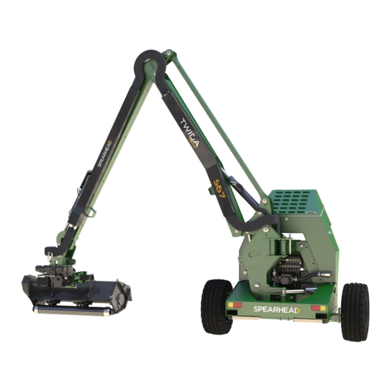
ORBITAL Introduction The Orbital is a very robust high capacity reach mower that is easy to operate and maintain. To ensure trouble-free operation this manual should be carefully studied. The Orbital model can be fitted with the optional hydraulic undercarriage and pneumatic wheels for carrying the weight of the machine. -
Page 7: Specification
ORBITAL Specification Weight inc. Oil (Kg) 2155 2312 2372 2400 Weight of head (Kg) Tractor horse power 4500 4750 5000 6000 Min. tractor weight (Kg) Oil tank capacity (ltr) Reach A (m) Reach B (m) Reach C (m) Reach D (m) Reach E (m) -
Page 8: Safety Recommendation
ORBITAL Safety Recommendations Beware of the following Potential Dangers associated with the use of this machine: • Becoming trapped when hitching or unhitching • Tractor overbalancing when arm is extended • Electrocution due to hitting overhead power lines • Getting caught on rotating power take off (PTO) •... - Page 9 ORBITAL • Follow the manufacturer’s instructions for attachment and removal of machine from the tractor are warning signs to alert others to the type of machine working in the vicinity. Signs should be placed at both ends of the work site and should be in accordance with Department of Transport recommendations.
-
Page 10: Overhead Power Lines
ORBITAL Overhead Power Lines It cannot be stressed enough the dangers involved when working in the vicinity of Overhead Power Lines (OHPLs). Some of our machines are capable of reach in excess of 8 metres (26’); they have the potential to well exceed, by possibly 3 metres (9’... - Page 11 ORBITAL Definitions of Exclusion Zones Risk Assessment Before starting to work near OHPLs you should always assess the risks. The following points should be observed; Know the risks of contacting OHPLs and the risk of flashover. Find out the maximum height and maximum vertical reach of your machine. Find out the location and route of all Power Lines within the work area.
-
Page 12: Safety Decal
ORBITAL Safety Decal Warning Signs You are advised to display clear warning signs to indicate the type of machine when working in public places. The signs should be carefully placed at either end of the work site to give advanced warning of the hazard. Contact your local Highways Authority or Department of Transport for more information. -
Page 13: Lighting Kits
ORBITAL Training It is the responsibility of the Spearhead dealer to provide instruction on the safe installation, operation and maintenance of the machine in the first instance. Further training is available from Spearhead Machinery Ltd on request, at cost. Tractor Requirements •... -
Page 14: Attaching Your Machine To The Tractor - Using 3 Point Linkage
ORBITAL Attaching Machine to Tractor – 3 Point Linkage 1. Reverse tractor to machine and attach lower links. 2. Fit stabiliser bracket into top link clevis and fit top link. The standard link comes with a Cat III hole plus a Cat III to Cat II reducing bush, a 28mm bracket is available on request. - Page 15 ORBITAL 4. Raise machine to required height. Both P.T.O. shafts should be roughly in-line, an upward angle of up to 17° is acceptable to ensure adequate clearance. 5. Adjust the top link so that the machine sits vertically. 6. Fit locking pins to stabiliser tubes, then the linkage can be lowered so that the weight of the machine is taken by the stabilisers.
- Page 16 ORBITAL 7. It is recommended that the controls are mounted in-place of the seat armrest on the side of the cutting head. A pivoting bracket is supplied with every machine, if additional brackets are required contact your local dealer. A 12v/30Amp power supply will be required.
- Page 17 ORBITAL 9. Raise leg stands to ensure they do not get damaged. Adjust check chains ensure the machine is secure and cannot swing from side to side. 10. Use only tractors with safety glass. If windows are not laminated safety glass, polycarbonate glazing must be fitted between operator and cab meshing.
-
Page 18: Attaching Your Machine To The Tractor - Using Axle Mounting
If there is any doubt please contact your supplying dealer or Spearhead Service Department. Failure to follow the correct procedure To attach/unattached the machine could result in personal injury or machine damage. Any resulting damage to a machine is not covered by warranty. - Page 19 ORBITAL 3. Fit lift-in hitch assembly 4. Assemble sub frame to suit axle width 1m or 1.1m, mount sub frame assembly to your machine using bottom pin holes. 5. Offer up frame to tractor and adjust to give required length. Distance “X” to be kept to the minimum ensuring the machine is close coupled, as a guide set same as original Attach tractor lift links to frame with suitable...
- Page 20 9. Reverse tractor and attach lower link arms by inserting lower linkage pins into the bottom set of holes. 10. Spearhead strongly recommend mounting the control unit to the seat in place of the armrest to the head side of the tractor. Modification and additional bracket may need to be fabricated Consult your local dealer for advice.
- Page 21 ORBITAL 11. Fit stabiliser yoke to the tractor’s 11a. Make hydraulic connection to tractor top hitch bracket. external spools for wheel undercarriage and head slew. 2 double acting spools required. bracket. 12. Place the stabiliser tubes on to the frame using the pins.
- Page 22 ORBITAL 15. Check the machine is at the correct height and level, ensuring both stabiliser bars are at an equal length. Fit locking pins to both stabilisers. Once the stabilising bars are correctly fitted, lower the tractor hydraulics allowing all the weight of the machine to be carried by the stabiliser bars (use a pry bar to twist tube if necessary).
- Page 23 ORBITAL Adjust top link 19. Adjust top link length until the main frame is vertical. 20. Warning - fully tighten chains and linkage stabilisers to hold the machine rigid. There must be no sideways movement, it is very dangerous. 21. Remove parking stands and store safely. The machine cannot be unhitched without these stands.
-
Page 24: Running Up Your Machine
ORBITAL Warnings Avoid raising the tractor linkage once the stabiliser bars are locked in place. Always lower the tractor linkage and allow all the weight to be carried by the stabiliser frame. Failure to observe this warning will result in bending the stabiliser frame. 22. -
Page 25: Removing From The Tractor
ORBITAL Removing from The Tractor The following steps MUST be followed in exactly the same order in which they appear, with removal of the top link being the last action before driving the tractor away. Do not attempt to operate machine controls through the rear cab window whilst standing on or amongst the linkage. -
Page 26: Multipilot Controls
ORBITAL MULTIPILOT Controls Tele Tele LH - Tele Out LH - Tele In RH - Tele In RH - Tele Out Arm Float On Head Float On Slew Slew LH - Slew Out LH - Slew In RH - Slew In RH - Slew Out Head Crowd Head Crowd... - Page 27 ORBITAL MULTIPILOT Switch Box Hour counter logs rotor hours in forward or reverse: Warning It is critical that the rotor is given time to “run-down” and come to a complete stop before an alternate direction is selected, switching directly from one direction directly to the other will result in the system locking and could lead to premature failure.
-
Page 28: Operation Warnings
ORBITAL Operational Warnings • Never drive the tractor with arm outstretched (except when cutting). When moving at work always first retract arms. Transport with care. Metal fatigue is always caused by careless transportation and misuse. If the ground is uneven or bumpy slow down. •... -
Page 29: Moving Into Transport Position
ORBITAL Moving Into Transport Position Warning Always transport machine with the slew-locking pin fitted and the arms closed in the transport position on the bump stops. Avoid high transport speeds, which will cause unnecessary strain on machine and tractor. Never travel with the reach arm away from bump stop on the main arm failure to adhere to this warning will cause damage to ram seals and arms. - Page 30 ORBITAL +300m 3. Carefully position main boom over the tractor cab roof, allow a minimum of 300mm. 4. Fit slew locking pin. Warning: Do NOT attempt to slew machine until pin has been removed. 5. Fit the transport link between the lift frame and slew post.
-
Page 31: Operation
ORBITAL Operation Transport to work position • Remove locking pin from slew post. • Turn lift ram isolation tap to on position. • Ensure rotor/motor switch is off. • Engage PTO low revolutions. • Lower main lift ram only, until main arm is vertical. •... -
Page 32: Auto Reset
ORBITAL Break Back Manual - Switch “Off” The Twiga range of reach mowers have as standard a slew ram to position the machine from transport to work or any position midway for narrow lane cutting. This ram also acts as the break back ram for machine protection should an obstacle be encountered while travelling forward. -
Page 33: Oil Cooler
ORBITAL Oil Cooler The standard fitment of an oil cooler prolongs the life of the hydraulic oil and components in hot and arduous conditions. It is important to connect the power lead to the control box directly to the tractor battery. It is essential to keep the radiator clear from debris to ensure a free air flow that will effectively keep the oil cool. -
Page 34: Head Float
ORBITAL Head Float Head Float This option allows the flail head to follow contours of the ground without having to constantly control the angle of the head. The centre of balance is the best mounting point for the head if head float is to be used properly. -
Page 35: Arm Float
ORBITAL Arm Float Arm Float This is only to be used in verge mowing set up, it will reduce weight on the rear roller allowing head to move more easily, following small changes in ground contours in a forward motion, with the aid of a pre-charged gas accumulator. Operating the Arm Float To select arm float, first lower the flail head to the ground before operating the switch on the joystick. -
Page 36: Debris Blower
ORBITAL Debris Blower Hydraulically driven fan from tractor external services, please quote tractor oil flow when ordering (maximum 40lt per min). The return oil must go to a free flow connection i.e. filler plug. Avoid quick release couplings. Operating the Debris Blower The fan is suitable for clearing cuttings off the highway;... -
Page 37: Hydraulic Rear Roller
ORBITAL Hydraulic Rear Roller The hydraulic rear roller is controlled by the tractor spools or the Telescopic function on a Standard arm machine. The control of the rear roller is either raised or lowered, there is no in-between height control. Height is set as above for either hedge or grass cutting Note To ensure the roller moves freely it is important to keep the roller linkage clean... -
Page 38: Autopilot
. Warning Ensure you fully understand the operation of the Spearhead Autopilot, which will reduce machine and operator fatigue and improve hourly output, machine life, standard of work and comfort to the operator. - Page 39 ORBITAL Set-Up: Correct position of micro switches Bolt “A” Screw “B” Fig. 2 1. Place rear roller on the ground 2. Ensure the locking pins (fig.1) are installed into the Autopilot with the arm fully lowered 3. Engine turned off, key removed, and PTO disengaged. 4.
- Page 40 ORBITAL Summary You must ensure that the micro switches make and break a circuit as the cams rotate through their arc of travel. It is very important to correctly set the micro switches to ensure the electrical circuit functions, the switch lever arm must follow its own cam and not be influenced by the opposite cam also the lever must be bent towards or away from the cam to allow the electric circuit to open and close in accordance to the cam position...
- Page 41 ORBITAL Auto Pilot Switch Alignment Bend lever arm of switch to align with the middle of each cam, ensure they don’t overlap onto the adjacent cam. Alternative Settings Move the cams apart to increase amount of weight carried on the rear roller, thereby reducing the sensitivity of the auto-pilot If the cams are too close together...
- Page 42 The operator will control reach whenever necessary. The Spearhead Autopilot will assist you with grass mowing. It does not relieve you of your responsibility to drive with care and understanding for the machine.
-
Page 43: Telescopic Arm
ORBITAL Telescopic Arm Description Telescopic extending arm provides extra reach, particularly useful for deep ditches, banks and for reaching high hedges. Operating the Telescopic Arm Use the joystick buttons to adjust the length of the extending telescopic dipper arm to suit working conditions and use dipper ram to vary reach as required. Over frequent use of telescopic arm will cause premature wear of adjustable pads. -
Page 44: Height Limiter
ORBITAL Height Limiter The Height Limiter option is intended to provide a means to control the maximum height that the machine can work to but is limited by the setting chosen and the positioning of the cutting head. The system is turned OFF and ON via the toggle switch on the side of the controls box and is only activated when the cutting rotor is engaged. -
Page 45: Service & Maintenance
ORBITAL Service and Maintenance Daily grease points TWIGA machine Optional - Autopilot... -
Page 46: Torque Settings
ORBITAL Washing your machine Grease all your machine and optional parts after each time you wash your machine. Gearbox Before first use check gearbox oil level, thereafter check every 8 hours. After the first 50 hours drain and replace the gearbox oil, thereafter annually. Replace with EP90. -
Page 47: Hydraulic Hoses
• Hoses with damaged metal braid should be replaced. • When replacing hoses quote number stamped on fitting at one end. The Spearhead hydraulic system works at very high pressure, when replacing hoses use only genuine hoses, a burst hose could be very dangerous. -
Page 48: Oil Supply
ORBITAL Oil Supply • Daily before starting up check oil level in tank reservoir. • It is a good practice to constantly keep an eye on the tank level gauge, (this can be seen from the tractor seat) as a pipe burst could empty the tank within minutes. -
Page 49: Pin & Bushes
All main pivot points are furnished with replaceable bushes. If there are any signs of wear, these must be replaced. All bushes are available from Spearhead Parts Department. Warning Do not use grease containing Molybdenum disulphide on nylon bushes and wear pads. -
Page 50: Regular Service Chart
ORBITAL Regular Services Chart Service Hours Service points 1-4 hrs Bolts are fully tightened Condition of flails Condition of hoses especially for chafing Flail bolts are fully tightened Flail head retaining bolts are fully tightened Gearbox seals (If oil is leaking replace immediately) ( X ) Inspect leaks from fittings and pipes Pins and bushes... -
Page 51: Trouble Shooting
ORBITAL Trouble Shooting Problem Cause Solution Gearbox overheating Oil level incorrect Check oil level Oil grade incorrect Check oil grade Implement overloaded Reduce forward speed Wrong PTO speed Ensure tractor PTO speed matches implement Excessive belt wear Belt and pulley condition Replace if necessary Pulley alignment Check alignment... - Page 52 ORBITAL Trouble Shooting Problem Cause Solution Irregular arm movement Spool contacting with housing Check spool is free moving Broken spring in spool valve Check spring Failed ram seals Repair ram Electrically operated Faulty wiring Check wiring and switches valve not responding Dirt in valve Check of ingress of dirt Sticking valve...
- Page 53 ORBITAL Spearhead Machinery Ltd Green View Salford Priors Evesham Worcestershire WR11 8SW Tel: 01789 491860 Fax: 01789 778683 www.spearheadmachinery.com enquiries@spearheadmachinery.com...
- Page 54 ORBITAL Spearhead Machinery Ltd Station Road Salford Priors Evesham Worcestershire WR11 8SW Tel: 01789 491860 Fax: 01789 778683 www.spearheadmachinery.com enquiries@spearheadmachinery.com Spearhead Machinery Ltd Green View Salford Priors Evesham Worcestershire WR11 8SW Tel: 01789 491860 Fax: 01789 778683 www.spearheadmachinery.com enquiries@spearheadmachinery.com...
Need help?
Do you have a question about the ORBITAL S63 and is the answer not in the manual?
Questions and answers