
Related Manuals for Suncast Sierra BMS6550


Summary of Contents for Suncast Sierra BMS6550
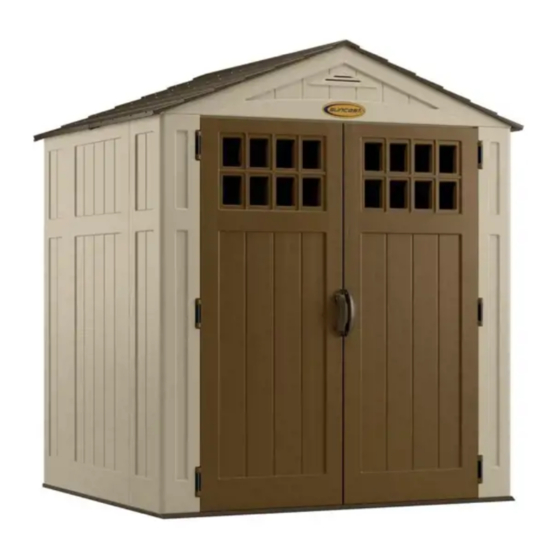
- Page 1 BMS6550 Shed – Sierra™ ASSEMBLY INSTRUCTIONS Quality Control Number: Assembled exterior dimensions 6' W. x 6' 5" D. x 7' 3" H. Numéro de controle de qualitié: Número de control de calidad: © 2012 Suncast Corporation, Batavia, IL 0361170 A...
- Page 2 Before You Begin... CAUTION DO NOT...
- Page 3 Note: This product contains parts that are used in different orientations to construct the shed. Please take note of the orientation of the parts shown throughout this instruction manual. Failure to follow instructions could result in damage to parts. Suncast is not responsible for replacing parts lost or damaged due to incorrect assembly.
- Page 4 0B00082 – Side 0B00083 – Left 0B00071 – Left 0B00087 –Back panel front corner back corner panel 0B00079 – Front Floor 0B00081 – Rear floor 0B00084 – Right front corner 0B00072 – Right back corner...
- Page 5 0B00077 – Left door 0440546 – Window gasket 0440544 – Window x1 set x1 set 0440631 – D-ring 0B00078 – Right door 0102102 – Door handle slide bolt x1 set...
- Page 6 0440537 – Roof ridge 0280399 – 5' Ridge beam beam bracket x1 set 0440630 – Vent screen 0B00086 – Rear header x1 set 0B00085 – Front header 0280372A – Header beam...
- Page 7 0B00073 – Left roof 0630820 – Truss bracket 010208810A – 0B00074 – Right roof Roof connector 0630818 – Truss leg 0630819 – Truss cross brace B AA 0630823 – Truss strap B BB 0630817A – Side adapter bracket x1 set...
- Page 8 0440627 – Hardware bag 0480215 – Hardware bag .25" x .75" .75" Sealing Machine screw screw .25" x 2" .25" x 1" .25" Locking Rubber Hex bolt Hex bolt washer Metal hinge plate 0480217 – Hardware bag 0480216 – Hardware bag 0480218 –...
- Page 9 Note: Site preparation is required for this shed. Placing the shed on a constructed foundation is required. Without a constructed foundation, settling will occur, causing distortion and damage to the shed. Suncast is not responsible for replacing parts damaged or property lost due to incorrect assembly.
- Page 10 (continued) Wood platform critical spacing 3 1/2" Outside to center of (D) board 14 1/2" Sub frame spacing 3/4" 11" Materials list Item Size 72" x 65 1/2" x 3/4" 2" x 6" x 65 1/2" 2" x 6" x 68 1/2" 2"...
- Page 11 Parts/hardware needed for door pre-assembly are shown on pages 5 and 8. Lay left door (N) on flat ground with window screw attachments facing up. Place window gasket (B) into length. Through backside of door, secure layers with thirteen screws (LL)—start with four corner screws and DO NOT over tighten screws.
- Page 12 Parts/hardware needed for header pre-assembly are shown on pages 6 and 8. peak of front header (K) and secure with two screws (MM). DO NOT over tighten screws. Repeat for rear header (L). Lay front header (K) on ground with lettering facing up. Place vent screen (U) into rear opening in front header (K).
- Page 13 Truss Pre-Assembly Parts/hardware needed for truss pre-assembly are shown on pages 7-8. Attach truss bracket (W) to end of one truss leg (Y) with 1" hex bolt (GG) and nut (HH). REPEAT WITH OTHER TRUSS LEG. Note: Make sure side hole is at other end, as shown in step 8.
- Page 14 Truss Pre-Assembly (continued) Place side adaptor bracket (BB) at end of left truss leg (Y). Secure adaptor bracket with one 2" hex bolt (FF) and one nut (HH). Note: DO NOT over tighten side adaptor bracket (BB) onto end of truss leg (Y). Roof panels will assemble to truss legs (Y) in later step.
- Page 15 Note: At least two people are needed during assembly. Note: Need to use a rubber mallet. Critical: When installing corners, flex corner hinges back and forth several times. This will help provide a square corner and ensure proper fit of remaining panels. Important: DO NOT flex in reverse position, as this can crack the panel.
- Page 16 Push front floor (A) and rear floor (C) panels together Align tab on bottom right side of left front corner (D) with and secure with four screws (LL). slot on front floor (A). Lower panel into slot and lock in place by sliding panel toward door opening.
- Page 17 Before proceeding, make sure corner is square (top view) where it meets the floor and that panel is flush (side view) with floor. If not, repeat Steps 12–14 until square and flush. Top view Top view Side view Side view Align tabs on bottom of side panel (E) with slots along front and rear floors.
- Page 18 Align tabs on bottom right side of left back corner (F) Tip left back corner (F) outward slightly and bend corner with slots along rear floor. Lower panel into slots and hinge. lock in place by sliding panel toward corner. Note: Use a rubber mallet to “push”...
- Page 19 floor to roof. DO NOT use torque wrench. Use easy bolt easy driver (KK) and hand tighten. Easy bolt head will be flush when fully seated. DO NOT over tighten easy bolts. Note: You may hear a click when easy bolt has been tightened completely.
- Page 20 floor to roof. DO NOT use torque wrench. Use easy bolt easy driver (KK) and hand tighten. Easy bolt head will be flush when fully seated. DO NOT over tighten easy bolts. Note: You may hear a click when easy bolt has been tightened completely.
- Page 21 Tip right back corner (H) outward slightly and bend the Tip right back corner (H) back to vertical position and corner hinge. align lower tabs on right side with slots in floor. Before proceeding, make sure corner is square (top view) where it meets the floor and that panel is flush (side view) with floor.
- Page 22 to roof. DO NOT use torque wrench. Use easy bolt easy driver (KK) and hand tighten. Easy bolt head will be flush when fully seated. DO NOT over tighten easy bolts. Note: You may hear a click when easy bolt has been tightened completely.
- Page 23 floor to roof. DO NOT use torque wrench. Use easy bolt easy driver (KK) and hand tighten. Easy bolt head will be flush when fully seated. DO NOT over tighten easy bolts. Note: You may hear a click when easy bolt has been tightened completely.
- Page 24 Before proceeding, make sure corner is square (top view) where it meets the floor and that panel is flush (side view) with floor. If not, repeat Steps 32–34 until square and flush. Top view Top view Side view Side view Tip right front corner back to vertical position and align lower tabs on right side with slots in floor.
- Page 25 Truss Assembly Note: At least two people are needed during assembly. protruding support legs on left and right front corners into pockets molded in front header. Tabs on front header must be seated in header channel pocket. Note: DO NOT leave front header unsupported until header beam (V) is secured (Step 38).
- Page 26 with six screws (LL). Note: Header beam (V) has large holes on one side and small holes on other side. The small holes must face header. x6 x6 protruding support legs on left and right back corners into pockets molded in rear header. Tabs on rear header must be seated in header channel pocket.
- Page 27 x8 x8 x6 x6 with six screws (LL). with four screws (LL) in each side adapter bracket. Note: Header beam (V) has large holes on one side and small holes on other side. The small holes must face header. Raise ridge beam (T) up and into rear roof ridge beam Note: Alignment of ridge beam to bracket may require Note: Alignment of ridge beam to bracket may require header panels to be pushed inwards or outwards slightly...
- Page 28 Note: At least two people are needed during assembly. Before proceeding, locate and identify channels on Before proceeding, locate and identify the six front interior side of right roof (O) and left roof (Q). Locate header tabs and six rear header tabs. three underside tabs contained within each channel.
- Page 29 x2 x2 x3 x3 Lay right roof (O) directly over the three tabs on right Pull down each lower corner of roof from outside. From side of front header (K). With right roof channel seated inside shed, attach tabs on side panel (E) and front right over/on header tabs, pull right roof downward at each header tab until roof snaps in place.
- Page 30 To lock right roof panels (O) in place, the top and middle roof connectors (X) slide up and the bottom roof connector (X) slides down. x4 x4 Pull down each lower corner of roof from outside. From inside shed, attach tabs on back corner (H) and side panel (E) roof panel with four screws (LL).
- Page 31 x2 x2 x3 x3 Pull down each lower corner of roof from outside. From Lay left roof (Q) directly over the three tabs on right side inside shed, attach tabs on side panel (E) and front left of front header (K). With left roof channel seated over/ corner (D) to roof panel with three screws (LL).
- Page 32 To lock in left roof panels (Q) in place, the bottom roof connector (X) slides down and the top and middle roof connectors (X) slide up. Bottom Bottom Middle Middle x4 x4 Pull down each lower corner of roof from outside. From inside shed, attach tabs on side panel (E) and back left corner (F) to roof panel with three screws (LL).
- Page 33 x2 x4 x6 x4 Push down the roof from outside. From inside shed, Attach truss strap (AA) to left truss tie down (BB) and secure roof panels together along ridge of roof using four Repeat for right side of truss. Note: For clarity, illustration is shown with front header, right front corner removed.
- Page 34 Note: At least two people are needed during assembly. hinge mount. Rotate hinge plates to outside of door. door. Repeat for left door (N).
- Page 35 metal hinge plate over each hinge receptacle on inside one nut (HH). of right front panel. Note: For clarity, illustration is shown with roof and ridge Note: For clarity, illustration is shown with roof and ridge beam removed. beam removed. Complete.
- Page 36 Warranty Factory Repairs...
Need help?
Do you have a question about the Sierra BMS6550 and is the answer not in the manual?
Questions and answers