Advertisement
Quick Links
Tools Needed for Installation
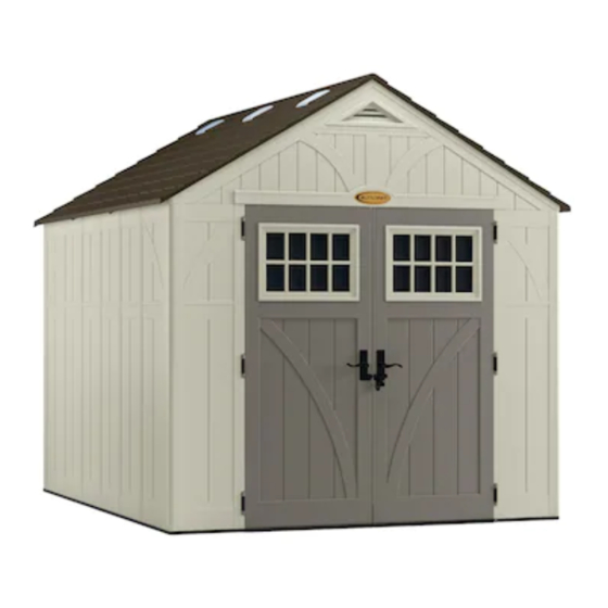
Blow Molded Resin Storage Shed
ASSEMBLY INSTRUCTIONS
Assistance is required
during entire assembly.
Thank you for your purchase. Please go to Suncast.com to register your product for warranty.
© 2021 Suncast Corporation, Batavia, IL
0361334F
Advertisement

Related Manuals for Suncast BMS8125


Summary of Contents for Suncast BMS8125
- Page 1 Tools Needed for Installation Blow Molded Resin Storage Shed ASSEMBLY INSTRUCTIONS Assistance is required during entire assembly. Thank you for your purchase. Please go to Suncast.com to register your product for warranty. © 2021 Suncast Corporation, Batavia, IL 0361334F...
- Page 2 • Read instructions thoroughly prior to assembly. This kit contains parts that can be damaged if assembled incorrectly or in the wrong sequence. • Please follow instructions. Suncast is not responsible for replacing parts lost or damaged due to incorrect assembly. • Assistance is required during entire assembly. IMPORTANT OPEN ALL BOXES FIRST AND NEATLY LAYOUT PARTS. SMALL PARTS MAY BE CONTAINED IN EACH BOX.
- Page 3 Note: This product contains parts that are used in different orientations to construct the shed. Please take note of the orientation of the parts shown throughout this instruction manual. Failure to follow instructions could result in damage to parts. Suncast is not responsible for replacing parts lost or damaged due to incorrect assembly.
- Page 4 IMPORTANT OPEN ALL BOXES FIRST AND NEATLY LAYOUT PARTS. SMALL PARTS MAY BE CONTAINED IN EACH BOX. PLEASE REFERENCE THE PARTS LIST WITHIN THIS MANUAL TO VERIFY ALL PARTS ARE PRESENT. COMPLETE SITE PREPARATION AND FOUNDATION CONSTRUCTION BEFORE UNPACKING ALL PARTS. Parts - Walls and Floors...
- Page 5 Parts - Doors IMPORTANT OPEN ALL BOXES FIRST AND NEATLY LAYOUT PARTS. SMALL PARTS MAY BE CON- TAINED IN EACH BOX. PLEASE REFERENCE THE PARTS LIST WITHIN THIS MANUAL TO VERIFY ALL PARTS ARE PRESENT. COMPLETE SITE PREPARATION AND FOUNDATION CONSTRUCTION BEFORE UNPACKING ALL PARTS.
- Page 6 Parts - Headers IMPORTANT OPEN ALL BOXES FIRST AND NEATLY LAYOUT PARTS. SMALL PARTS MAY BE CON- TAINED IN EACH BOX. PLEASE REFERENCE THE PARTS LIST WITHIN THIS MANUAL TO VERIFY ALL PARTS ARE PRESENT. COMPLETE SITE PREPARATION AND FOUNDATION CONSTRUCTION BEFORE UNPACKING ALL PARTS.
- Page 7 Parts - Truss IMPORTANT OPEN ALL BOXES FIRST AND NEATLY LAYOUT PARTS. SMALL PARTS MAY BE CON- TAINED IN EACH BOX. PLEASE REFERENCE THE PARTS LIST WITHIN THIS MANUAL TO VERIFY ALL PARTS ARE PRESENT. COMPLETE SITE PREPARATION AND FOUNDATION CONSTRUCTION BEFORE UNPACKING ALL PARTS.
- Page 8 Parts - Roof IMPORTANT OPEN ALL BOXES FIRST AND NEATLY LAYOUT PARTS. SMALL PARTS MAY BE CON- TAINED IN EACH BOX. PLEASE REFERENCE THE PARTS LIST WITHIN THIS MANUAL TO VERIFY ALL PARTS ARE PRESENT. COMPLETE SITE PREPARATION AND FOUNDATION CONSTRUCTION BEFORE UNPACKING ALL PARTS.
- Page 9 Hardware...
- Page 10 Door Handle Kit...
- Page 11 Note: Site preparation is required for this shed. Placing the shed on one of the constructed foundations detailed below is required. Without a constructed foundation, settling will probably occur, causing distortion and damage to the shed. Suncast is not responsible for replacing parts damaged or property lost due to incorrect assembly. Warranty r equires foundation.
- Page 12 Site Preparation and Platform Construction (continued) Materials NOT supplied with Shed Kit Wood platform critical spacing • Check all critical spacing measurements. Wood platform materials list 48" x 96" x ¾" Plywood 25¼" x 96" x ¾" 2" x 6" x 96" 2"...
- Page 13 Door Pre-Assembly Peel film from both sides of window (R). Remove Place gasket (U), window (R), and frame (T) into door protective film from door edge. channel. Secure with ten screws (JJ), starting at corners. DO NOT over tighten screws. Repeat for right door (M). Note: The cut portion of gasket (R) MUST be assembled on bottom of door channel.
- Page 14 Header Pre-Assembly Lay front header (J) on ground with lettering side facing Place header beam (Z) into pocket of front up. Place fiberglass vent screen (Y) into rear opening in header (J). Secure with six screws (JJ). DO NOT over front header (J).
- Page 15 Ridge Beam Pre-Assembly Place ridge beam joiner (DDD) into the 3' ridge beam (EEE). Secure with hex bolt (MM) and nut (LL). Part (EEE) orientation is critical, see picture. Place 7' ridge beam (V) onto the ridge beam joiner (DDD). Secure with hex bolt (MM) and nut (LL).
- Page 16 Roof and Truss Pre-Assembly Attach truss bracket (CC) to end of one truss leg (AA) Attach two truss cross beams (EE) to two truss legs with one hex bolt (RR) and one nut (LL). (AA) with two cap screws (MM) and two nuts (LL). Stand truss and check cross beam is level.
- Page 17 Shed Assembly/Walls Repeat Step 15 for left floor extension (C) and right floor Push left floor (A) and right floor (B) panels together and extension (D). Secure with 15 screws. secure with six screws (JJ). Note: Refer to pages 11 and 12 to secure floors to Note: Refer to pages 11 and 12 to secure floors to foundation.
- Page 18 Shed Assembly/Walls (continued) Align tab on bottom of left front corner (E) with slot on Tip left front corner (E) outward slightly and bend corner hinge. left floor (A). Lower panel into slot and lock in place by sliding panel toward door opening. Note: Use a rubber mallet to “push”...
- Page 19 Shed Assembly/Walls (continued) Align tabs on bottom of side panel (F) with slots along floor (A). Lower panel into slots and lock in place by sliding panel toward front corner. Note: Use a rubber mallet to “push” side panel (F) into locked position. Secure side panel (F) with four easy bolts (NN), working from floor to roof.
- Page 20 Shed Assembly/Walls (continued) Repeat Steps 17-22 for remaining panels.
- Page 21 Shed Assembly/Headers and Truss Place front header (J) over door opening and fit four Place rear header (K) over back walls and fit four protruding support legs into pockets molded in front protruding support legs into pockets molded in back corners.
- Page 22 Shed Assembly/Headers and Truss (continued) Attach the roof truss assembly to the ridge beam with Attach truss strap (GG) to side adaptor bracket (FF) with two screws (JJ). two screws (JJ). Repeat for remaining truss straps. Shed Assembly/Roof Before proceeding, locate and identify the six slots on interior side of right and left roof panels.
- Page 23 Shed Assembly/Roof (continued) Lay right roof (O) directly over three tabs on right side Before proceeding, locate and identify six front header of front header (J). With right roof slots seated over/on tabs and six rear header tabs. header tabs, check alignment in all three spots. Press edge of right roof (O) into channel on truss leg (AA).
- Page 24 Shed Assembly/Roof (continued) Repeat Steps 30-32 for remaining roof panels. Install panels in the order shown. Note: At this point, fully tighten ALL hardware. Pull down each lower corner of roof from outside. From Secure roof to truss using six screws (JJ). Each screw inside shed, attach tabs on right front corner (I) and side will attach at a corresponding screw boss on the roof.
- Page 25 Shed Assembly/Roof (continued) Secure roof support to roof using three screws (JJ). Raise roof support bracket (DD) into position against roof. Slide roof support bracket (DD) into front header. Secure Repeat Steps 36-37 to install and secure remaining roof support bracket (DD) to underside of truss leg with roof support brackets to three outer roof panels.
- Page 26 Shed Assembly/Roof (continued) Push down the roof from outside. From inside shed, secure roof panels together along ridge of roof using nine rubber washers (QQ) and nine sealing screws (PP). Note: For clarity, illustration is shown with front header and right front corner removed. Shed Assembly/Doors Stand right door (M) upright with three hinge mounts With door hinge in open position, slide one door hinge...
- Page 27 Shed Assembly/Doors (continued) Secure each metal hinge plate with one screw (KK) and Insert two screws (CCC), into left latch plate (OO), and one nut (LL). through pre-drilled holes in doors. While holding plate in place on exterior door, secure with two washers (RR) and Repeat Steps 41-43 for left door (L).
- Page 28 Shed Assembly/Doors (continued) Push D-ring (E) up to engage with slot in header. Turn Push D-ring (E) down to engage with hole in floor. Turn D-ring to left for locked position. D-ring to left for locked position. Attach a 5/16" lock (not provided) to door handles, to Attach shelf (YY) in desired location with four screws (JJ) properly secure shed.
Need help?
Do you have a question about the BMS8125 and is the answer not in the manual?
Questions and answers