Table of Contents
Advertisement
Advertisement
Table of Contents

Subscribe to Our Youtube Channel
Related Manuals for Marantz SR-14EX


Summary of Contents for Marantz SR-14EX
- Page 1 Model SR-14EX User Guide AV Surround Receiver...
- Page 2 VIDEO SYSTEM CONNECTIONS FOR VIDEO COMPONENTS AUDIO VIDEO S-VIDEO AUDIO VIDEO S-VIDEO COAX DIG .1 DIG .2 DIG .3 DIG .4 DIG .5 DIG .6 RF IN DIGITAL AUDIO VIDEO S-VIDEO AUDIO DVD PLAYER MONITOR TV LD PLAYER S-VIDEO (FRONT) FRONT SURROUND FM (75...
- Page 3 SWITCHED 120W 1A UNSWITCHED 120W 1A UNSWITCHED 120W 1A LINE IN MAIN AMP (For MULTI ROOM) To a component with REMOTE VIDEO (Marantz RC-5 D-BUS) jacks Refer to OTHER CONNECTIONS (Page iii) IR RECEIVER MULTI ROOM INPUT MULTI ROOM SPEAKER...
-
Page 4: Other Connections
OTHER CONNECTIONS (Connectio with external 3ch amplifiers for Front+L, Front+R and subwoofer) OTHER MULTI CHANNEL PROCESSOR FRONT FRONT COAX COAX FRONT FRONT DIG .1 DIG .1 S2 IN S2 IN DIG .2 DIG .2 DIG .3 DIG .3 DIG .4 DIG .4 DIG .5 DIG .5... - Page 5 CAUTION: TO REDUCE THE RISK OF ELECTRIC SHOCK, REFER SERVICING TO QUALIFIED SERVICE PERSONNEL WARNING TO REDUCE THE RISK OF FIRE OR ELECTRIC SHOCK, DO NOT EXPOSE THIS APPLIANCE TO RAIN OR MOISTURE. CAUTION: TO PREVENT ELECTRIC SHOCK, MATCH WIDE BLADE OF PLUG TO WIDE SLOT, FULLY INSERT.
-
Page 6: Important Safety Instructions
IMPORTANT SAFETY This product was designed and manufactured to meet strict quality and safety standards. There are, however, some installation and operation precautions which you should be particularly aware of. Read Instructions - All the safety and operating instructions should be read before the appliance is operated. Retain Instructions-The safety and operating instructions should be retained for future reference. - Page 7 Servicing-Do not attempt to service this video product yourself as opening or removing covers may expose you to dangerous voltage or other hazards. Refer all servicing to qualified service personnel. Damage Requiring Service-Unplug this video product from the wall outlet and refer servicing to qualified service personnel under the following conditions: When the power-supply cord or plug is damaged.
- Page 8 ! 1 ! 2 ! 3 RC5000i MUTE CHANNEL VOLUME...
-
Page 9: Table Of Contents
TABLE OF CONTENTS INTRODUCTION ... 5 DESCRIPTION ... 5 FEATURES ... 6 FRONT PANEL FEATURES ... 7 DISPLAY ... 9 REAR PANEL CONNECTIONS... 10 REMOTE CONTROL UNIT RC5000i ... 12 OPERATION OF REMOTE CONTROL UNIT ... 14 SETUP ... 15 ON SCREEN DISPLAY MENU SYSTEM ... -
Page 10: Introduction
Please take a few minutes to read this manual thoroughly before you connect and operate the SR-14EX. As there are a number of connection and configuration options, you are encouraged to discuss your own particular home theater setup with your Marantz A/ V specialist dealer. -
Page 11: Features
• HDCD decoding capability to deliver the full sonic benefits of HDCD-encoded CDs from a standard non-HDCD CD player when connected to the SR-14EX via the player ’s digital output. • 96 kHz/ 24 bit decoding for highest possible fidelity and bandwidth, and high-resolution playback of 96 kHz/ 24 bit PCM audio sources. -
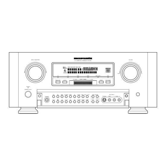
Page 12: Front Panel Features
PHONES jack for stereo headphones This jack may be used to listen to the SR-14EX’s output through a pair of headphones. Be certain that the headphones have a standard 1 / 4" stereo phone plug. -
Page 13: Auto Tuning Button
! 4 AUX input jacks These auxiliary video/audio input jacks accept the connection of a camcorder, portable VCR, etc. ! 5 INPUT SELECTOR knob When this knob is turned, the input signal is switched in the following sequence. TUNER TAPE CD-R/MD DSS/VCR2 VCR1... -
Page 14: Display
This indicator lights when VCR1 COPY. TAPE, COPY, or DIGITAL COPY system is active. (8) Night Mode Indicator This indicator lights when the SR-14EX is in the Night mode, which reduces the dynamic range of digital program material at low volume levels. -
Page 15: Rear Panel Connections
REAR PANEL CONNECTIONS All connections to the rear panel should be made with the entire system powered off. To avoid errors, it is advisable to connect one cable at a time between the various components. 21 10 FRONT SURROUND COAX COAX FRONT SURROUND... -
Page 16: Subwoofer Output
Both SWITCHED and UNSWITCHED outlets are provided. The one marked SWITCHED provides power only when the SR-14EX is turned on and is useful for components which you use every time you play your system. The one marked UNSWITCHED is always live as long as the SR-14EX is plugged into a live outlet. -
Page 17: Remote Control Unit Rc5000I
These buttons are used to select the SURROUND mode. CONTROL Power on / off buttons These buttons are used to turn on or off SR-14EX Night button This button is used to set night mode. This feature reduces the input level of dolby digital sources by 1/3 to 1/4 at their loudest... - Page 18 AM ,(LW) ,FM buttons These buttons are used to switch between FM, AM, and LW mode of the tuner. LW button is not available in SR-14EX. Seek (^ :up / v : down ) buttons These buttons are used to change the frequency.
-
Page 19: Operation Of Remote Control Unit
1. Remote control The distance between the transmitter of the remote control unit and the IR SENSOR of the SR-14EX should be less than about 15 feet. If the transmitter is pointed to a direction other than the IR SENSOR or if there is an obstacle between them, remote control may not be possible. -
Page 20: Setup
After all components are connected, initial setup must be performed. ON SCREEN DISPLAY MENU SYSTEM The SR-14EX incorporates an on-screen menu system, which makes various operations possible by using the cursor ( <, >, ^, buttons on the “SETUP” screen in the remote handset. -
Page 21: Osd Menu System
SPEAKERS SETUP AND LEVELS SETUP SPEAKERS SETUP Speakers size The first few adjustments tell the SR-14EX which type of speakers are in use. This is important as it adjusts the settings that determine which speakers receive low frequency (bass) information. - Page 22 After input for each speaker’s distance has been finished ,move cursor to ENTER with ^ or button and press the ok button. If your input is out of the range of the SR-14EX’s processing, “incomplete channel” will flash. In that case, input an acceptable parameter or improve the speaker placement.
- Page 23 When the digital output of a DVD player is connected to Digital 4 DSS/VCR2 (input jack) of the SR-14EX and an AC-3 RF output and optical digital output from a LD player are connected to AC-3 RF(Dig.6) and Dig.1. Move the cursor on the DVD with ^ or button.
-
Page 24: On Screen Display Infomation
S – SOURCE DIRECT : Switch the source direct ON or OFF with < or > button. In this mode, SR-14EX bypasses the digital processing and crossover for the main speakers (front left and right will be full range and the... -
Page 25: Basic Operation
To select the tuner as the source, turn the INPUT SELECTOR knob !5 on the front panel or press the Tuner button on the remote. Press the BAND button y on the SR-14EX or AM/FM buttons on page of Tune mode on the remote to select the desired frequency band. -
Page 26: Playback Operation
This function automatically scans the LW, MW and FM band and enters all stations with proper signal strength into the memory. This function is available only for SR-14EX. Select the FM band with the BAND button y. Tune in the lowest receivable frequency. -
Page 27: Other Functions
The Multi Room Selector is a function which allows you to listen to the same or a different source in a room other than the room in which the SR-14EX is located. To use this function, a multi room remote unit and remote control signal receiver available from your Marantz dealer are necessary. -
Page 28: Surround Modes
SURROUND MODES The SR-14EX incorporates digital signal processors (DSP) which can reproduce various surround effects you experience in concert halls and movie theaters, etc. Nine Surround Modes, are provided to reproduce a variety of surround sound effects, according to the content of the source to be played. - Page 29 The relation between the selected surround mode and the input signal The surround mode is selected with the surround mode buttons on SR-14EX or the remote control unit. However, the sound you hear is subject to the relationship between the selected surround mode and input signal. That relationship is as follows;...
- Page 30 Surround Input signal Output mode SL/SR SbL/SbR 5ch Stereo AC-3(5.1ch) AC-3(2ch) AC-3(2ch: Lt/Rt) AC-3 (EX) 96kHz PCM PCM(audio) PCM(HDCD) Analog DTS(5.1ch) STEREO AC-3(5.1ch) AC-3(2ch) AC-3(2ch: Lt/Rt) AC-3 (EX) 96kHz PCM PCM(audio) PCM(HDCD) Analog DTS(5.1ch) MONO AC-3(5.1ch) AC-3(2ch) AC-3(2ch: Lt/Rt) AC-3 (EX) 96kHz PCM PCM(audio) PCM(HDCD)
-
Page 31: Troubleshooting
If your trouble cannot be recovered with the remedy actions listed in the following table, malfunction of the internal circuitry is suspected; immediately unplug the power cable and contact your dealer, nearest Marantz distributor or the Marantz Service Center in your country. CAUSE Connect the power plug to the outlet. - Page 32 Should the operation or display seem to be abnormal, reset the unit with the following procedure. The SR-14EX is turned on, press and hold the CL (CLEAR) o and DISPLAY OFF @0 buttons simultaneously for 3 seconds or more. Remember that the procedure will reset the settings of the function selector, Surround mode, delay time, TUNER PRESET etc., to their...
-
Page 33: Technical Specifications
TECHNICAL SPECIFICATIONS FM TUNER SECTION Frequency Range ... 87.5 - 108.0 MHz Usable Sensitivity ... IHF 1.8 V/16.4 dBf Signal to Noise Ratio ... Mono/Stereo 76/72 dB Distortion ... Mono/Stereo 0.2/0.3 % Stereo Separation ... 1 kHz 45 dB Alternate Channel Selectivity ... Image Rejection ... - Page 34 P.O. Box 685, Bell Village, Port Louis, Mauritius PO BOX 1280, Sandhausen 69200, Germany A division of Marantz Europe B.V., Building SFF2, P.O. Box 80002, 5600 JB Eindhoven, The Netherlands 14 Malvern Road, Mt. Albert, Auckland, New Zealand Sandkerveien 64, Oslo 0483, Norway P.O.
Need help?
Do you have a question about the SR-14EX and is the answer not in the manual?
Questions and answers