Marantz SR-12S1 Service Manual
Av surround receiver
Hide thumbs
Also See for SR-12S1:
- User manual (58 pages) ,
- Service manual (76 pages) ,
- User manual (328 pages)
Table of Contents
Advertisement
Quick Links
Service
Manual
SECTION
1. TECHNICAL SPECIFICATIONS AND SERVICE TOOL ........................................ 1
2. TECHNICAL DESCRIPTION ................................................................................. 4
3. WIRING DIAGRAM................................................................................................ 7
4. BLOCK DIAGRAM................................................................................................. 9
5. SCHEMATIC DIAGRAM ...................................................................................... 11
6. PARTS LOCATION .............................................................................................. 33
7. IC DATA................................................................................................................ 53
8. EXPLODED VIEW AND PARTS LIST ................................................................. 63
9. SERVICE PROGRAM.......................................................................................... 67
10. UPDATE FIRMWARE .......................................................................................... 69
11. POWER AMPLIFIER ADJUSTMENT .................................................................. 71
12. SYSTEM ERROR ................................................................................................ 73
13. TROUBLE SHOOTING ........................................................................................ 75
14. ELECTRICAL PARTS LIST ................................................................................. 77
Please use this service manual with referring to the user guide ( D.F.U. ) without fail.
All manuals and user guides at all-guides.com
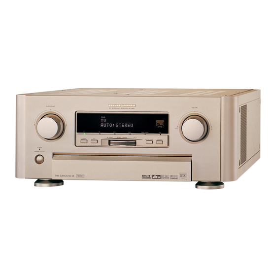
AV SURROUND RECEIVER SR-12S1
SURROUND
DISP
CINEMA
ST
PRO LOGIC
MOVIE
MUSIC
AUTO
DIRECT
AUTO SURR
THX SURR EX
TUNED
TEST
COPY
NIGHT
MULTI
SLEEP
M-SPKR
DOWN
TUNER
F/P
STAMDBY
POEWER ON/OFF
LD
DVD
DSS
TV
VCR1
VCR2/DVD-R
PHONES
AUX1
AUX2
7.1CH INPUT
ATT
S-DIRECT
MEMO
TABLE OF CONTENTS
SR-12S1
AV Surround Receiver
VOLUME
MUSIC
ANALOG
OTHER PCM
L
C
R
PRO LOGIC
ATT
LFE
DIGITAL
DIGITAL
SURROUND
SL
S
SR
DISC 6.1
MTX 6.1
PEAK
96kHz
SLEEP
DOWN
GYRO TUNING
UP
AUTO TUNE
T-MODE
AUX1 INPUT
CD
TAPE
CD-R/MD
DIGITAL
S-VIDEO
VIDEO
L
AUDIO
R
CLEAR
MULTI SPKR
MULTI ROOM
SR-12S1 /
N1G/N1S
UP
PAGE
Part no. 05AJ855010
First Issue 2003.08
ecm
Advertisement
Table of Contents

Related Manuals for Marantz SR-12S1


Summary of Contents for Marantz SR-12S1
-
Page 1: Table Of Contents
All manuals and user guides at all-guides.com Service SR-12S1 / N1G/N1S Manual AV Surround Receiver AV SURROUND RECEIVER SR-12S1 SURROUND VOLUME DISP CINEMA MUSIC ANALOG OTHER PCM PRO LOGIC MOVIE MUSIC PRO LOGIC DIGITAL DIGITAL AUTO SURROUND DIRECT AUTO SURR THX SURR EX DISC 6.1... - Page 2 Parts for your MARANTZ equipment are generally available to our National Marantz Subsidiary or Agent. ORDERING PARTS : Parts can be ordered either by mail or by Fax.. In both cases, the correct part number has to be specifi ed.
-
Page 3: Technical Specifications And Service Tool
All manuals and user guides at all-guides.com 1. TECHNICAL SPECIFICATIONS AND SERVICE TOOL TECHNICAL SPECIFICATIONS FM TUNER SECTION VIDEO Frequency Range ........87.5 - 108.0 MHz Television Format ..........NTSC/PAL Usable Sensitivity ......IHF 1.8 µV/16.4 dBf Input Level/Impedance......1 Vp-p/75 ohms Signal to Noise Ratio ..... - Page 4 The relation between the selected surround mode and the input signal The surround mode is selected with the surround mode buttons on SR-12S1 or the remote control unit. However, the sound you hear is subject to the relationship between the selected surround mode and input signal. That relationship is as follows;...
- Page 5 All manuals and user guides at all-guides.com Output Channel Front information display Surround Mode Input Signal SL SBL Signal format L/R C SubW Channel status Dot matrix display Segments SR SBR indicators DOLBY Dolby D Surr. EX O O O O O DIGITAL L,C,R,SL,SR,S,LFE DOLBY D...
-
Page 6: Technical Description
Dolby Laboratories and the THX division of Lucasfilm Ltd. correcting the tonal and spatial errors that occur. When the THX mode of the SR-12S1 is on, three distinct THX In a movie theater, film soundtracks that have been encoded with... - Page 7 All manuals and user guides at all-guides.com • Neo 6 technology allows various sound elements within a channel Dolby Digital EX creates six full-bandwidth output channels from 5.1- or channels to be steered separately, and in a way which follows channel sources.
- Page 8 All manuals and user guides at all-guides.com Remark : Bass signal output from Sub Woofer terminal. Sub woofer output is not active while all surround modes. Please refer to the following table. SPK setup SubWoofer Output by Surround mode ZR38601 Surr.
-
Page 9: Wiring Diagram
All manuals and user guides at all-guides.com 3. WIRING DIAGRAM PH-4P,PH-13P Shield PH-2P,PH-13P Shield WL71 PH-5P,PH-13P Shield pH-2P,pH-13P Shield 9 10 11 12 13 JX05 JL05 AUDIO JS04 PQ04 JP03 S-VIDEO AUDIO INPUT(1) CVBS PL04 AUX INPUT INPUT(2) PX04 PS04 PP04 JX07 JX06... -
Page 10: Block Diagram
All manuals and user guides at all-guides.com 4. BLOCK DIAGRAM From Tuner-M From M-Ch in TUNER L/R M_F(L/R) FRONT L/R M F(L/R) FRONT L/R CD(L) CD(L) CD(R) CD(R) To Function SEL E-VR Level Sens AUX(L/R) FRONT L CD IN TC9459N P-AMP M-SURR(L/R) From Front AUX... -
Page 11: Schematic Diagram
All manuals and user guides at all-guides.com 5. SCHEMATIC DIAGRAM PP94 HEAD PHONES OUT P114 R142 10 1/4w 36.9 37.0 R113 R117 41.4 36.0 JP99 Q107 D101 CP92 Q114 +18V 2SA970 R124 2SC3421 CP91 Dummy 35.0 C148 JP93 Q109 Dummy CP93 2SA1145 Q112... - Page 12 All manuals and user guides at all-guides.com From J503(P414) P154 From W504(P114) J504 P414 J503 100p 100p 100p 100p C504 C503 C502 C501 R508 R507 R506 R505 (RME)X401 R509 From J401(P114) C414 47/100V P-GND 37.0 CN16 RN44 Q414 10/50V 2SC3421 6.8K QN10 +Sbr...
- Page 13 All manuals and user guides at all-guides.com To u-COM J811 P814 Q812 PST600D R811 47/25V D811 8.7V 470 1/6w 5.1V C812 (RBU)X811 C816 D812 D817 R812 R813 5.1V Q811 78M05 D813 10.4V L811 Backup Trans. D814 AC13V C815 C817 100/16 V D815 Main Transformer C804...
- Page 14 All manuals and user guides at all-guides.com PG04 CE16 100p CE06 100p -15V RE16 RVR(XEXX) 8.2K TO J151(P154) 3CH AMP TO J101(P114) 3.5CH AMP -15V QE03 RE06 NJM2068DD QE01 CE20 RE20 RE22 RE28 NJM2068DD OP-AMP1/2 (XGXX) CE10 CE12 47/25V OP-AMP1/2 CE02 CE43 22/50V...
- Page 15 All manuals and user guides at all-guides.com LL01 CL65 10/50 V CL66 0.01 10/50V RVM-*F**/RVC-*L** PL04 JL06 CF09 12MQ-ST- L JL01 MULTI_OSD OSD_SEL -5VV CF10 L:THROUGH CF02 10/50V RL01 10/50V H:OSD 10/50V RL44 RF05 MONI2 CF01 10/50V CF33 CF25 1000 p LL02 SEL_VA CF20...
- Page 16 All manuals and user guides at all-guides.com -15V -15V RS05 CS05 TUN-L RRJ(XSXX) PS04 JUMPER CS77 RS75 RS07 RRM(XSXX XQXX) CS03 PS54 DUMMY AUDIO FUNCTION DUMMY JUMPER 10/50V RS77 MULTI CH IN NJM4558M D QS04 CS75 DUMMY CS04 RS08 JS01 DUMMY DUMMY NJM2068DD...
- Page 17 All manuals and user guides at all-guides.com PY04 5VLG 5VLG RCN-*Y**/RVR-*M,W**/RTU-*T** RTR-*9**/RPS-*8** QY01 TC74HC368A +15V +5VL +5VD +3.3V 5VLG D-GND D-GND D-GND D-GND W803 +5VL 5VLG EH-4P _PDOW N STANDBY +5VL D-GND +5VL +5VL +5VD +5VL MLTMUTE TUNEMUTE KILRDS SBMUTE 5VLG JY28 DAMM Y...
- Page 18 All manuals and user guides at all-guides.com DA01 1SS302 JD02 CA14 19PS-JE JD01 RA11 100K 12MQST CA01 RA06 QA01 +5VA +5VA -15V RH61 CH45 22/50V D-GND D-GND RA01 RH53 QH05 74HCU04AF QA01 RD01 RD09 4.7K 2068M RA16 74HCU04AF QD01 CH29 DA02 1SS302 4.7K...
- Page 19 All manuals and user guides at all-guides.com P604 1/2 +5V-A +5V-A +5V-A CR44 IIC Address 74244 series notes Input Output JR30 LR30 RR30 74VHC08 DSP initialize Puls Trans. QR44 12MQST COAXOUT CS49329 J60 1 to A/D,D/A PCB CR30 CS49330 CR34 RR31 OPTOUT IIC Expander1...
- Page 20 All manuals and user guides at all-guides.com P604 2/2 +5VL RU22 +5VL +5VL +5VL +5VL SU01 Tact SW(DUMMY) JU01 +3.3V JTAG 20P(DUMMY) RU17 CU21 4.7K SU02 QU20 74VHC00 SPUN PST600D QU02 _EMOE1 RU14 QU21 QU20 74VHC00 JU80 QU03 74VHC125 RN2303 LGA6502-0150 +5VL QU80...
- Page 21 All manuals and user guides at all-guides.com TO JU04(P604) µ -COM/DSP TO J838(P834) SUPPLY WC01 WC03 JC02 CC28 S3B-EH 0.01 RC31 DUMMY JC01 PC04 YP06003930 +5VLED 23FE-ST-VK-N CC20 CC21 CC27 0.01 10/50V +5VL 100/6.3V CC31 CC22 0.47 JUMPER RC32 100/6.3V CC32 CC23 CC24...
-
Page 22: Parts Location
All manuals and user guides at all-guides.com 6. PARTS LOCATION P604 QU60 - QU69 DU81 QU41 QU02 Q681 QU80 - QU86 DU80 QU70 QU01 QU03 QU05 QU43 Q683 Q684 QU20 Q671 Q670 QU50 QU71 Q676 Q600 Q601 Q611 QU42 Q682 Q685 QU21 Q641... - Page 23 All manuals and user guides at all-guides.com PD04 QK02 QK04 QK06 DK02 QH01 QH03 DK71 DA01 - DA04 QA01 - QA06 QK01 QK07 QK03 QK08 QD01 - QD04 QH05 QH02 QH04 DK70 QA07 QK51 QK05 DK01 QJ01 QJ02 QJ03 QJ04 DK03 QK52 DK05...
- Page 24 All manuals and user guides at all-guides.com PY04 DM81 - DM91 DM92 DM93 QM81 QW01 QY01 QM83 - QM90 QT03 Q951 QW31 QM82 QT02 QT04 Q901 Q902 Q855 Q852 D860 Q854 D862 D861 D863 Q853 D868 Q858 D866 Q857 D865 Q856 D867 Q903...
- Page 25 All manuals and user guides at all-guides.com PC04 QC08 QC04 QC01 QC02 QC03 QC07 QC06 QC05...
- Page 26 All manuals and user guides at all-guides.com...
- Page 27 All manuals and user guides at all-guides.com P134 P174 Q111 Q161 P214 P254 Q211 Q261 P314 P354 Q311 Q361 PN14 PN24 PN54 PN64...
- Page 28 All manuals and user guides at all-guides.com PG04 QM60 QM61 QE05 - 08 QE55- 58 QG05 - 08 QG55 -58 QM05 - 08 QE31 QE32 QE41 QE40 QE01 - 03 QE51 - 53 QG01 - 03 QG51 - 53 QM01 - 03 QM30 QE07 QE01...
- Page 29 All manuals and user guides at all-guides.com PL04 QL12 QL13 - QL15 QF04 QL08 QL09 QL10 QL04 QL18 - QL20 QL07 QL16 QL11 QL17...
- Page 30 All manuals and user guides at all-guides.com PS04 QS02 QS01 P124 QN04 - QN06 DN07 DN05 PP94 P824...
- Page 31 All manuals and user guides at all-guides.com P834 D839 D840 Q505 D501 Q504 Q506 Q507 Q508 DN01 - DN04 D503 Q833 Q831 Q832 D831 - D838 D502 PC74 QC70...
- Page 32 All manuals and user guides at all-guides.com PQ04 QQ02 QQ03 QQ01 QQ09 QQ08 QQ07 QQ06 QQ05 QQ04 PC64 QC60 QC61 P654...
- Page 33 All manuals and user guides at all-guides.com PF14 DF51 QF51 QF54 DF54 DF52 QF52 DF53 QF53 PP04 QP01...
- Page 34 All manuals and user guides at all-guides.com PX04 QX07 QX04 QX03 QX01 QX02 QX06 QX05 PS04 QS02 QS01...
- Page 35 All manuals and user guides at all-guides.com P814 Q802 Q803 Q801 Q811 Q812 PS54 QS71 QS72 QS70 QQ71 QQ72...
- Page 36 All manuals and user guides at all-guides.com P164 DN09 DN06 DN08 PY54...
-
Page 37: Ic Data
All manuals and user guides at all-guides.com 7. IC DATA Q671 : MBM29LV400TC Pin Assignment Pin Configuration (Marking Side) BYTE Function to A Address Inputs to DQ Data Inputs/Outputs Chip Enable N.C. Output Enable N.C. Write Enable MBM29LV400TC/MBM29LV400BC RESET RY/BY Ready/Busy Output N.C. - Page 38 All manuals and user guides at all-guides.com Q901 : LC72722M Pin Functions Pin No. Pin name Function Pin circuit Vdda VREF Reference voltage output (Vdda/2) Output Vssa A12365 Vdda MPXIN Baseband (multiplexed) signal input Input Vssa A12366 Ð FLOUT Subcarrier output (filter output) Output A12367 Vdda...
- Page 39 All manuals and user guides at all-guides.com QR50 : LC89055W Pin Functions Pin name Function DISEL Data input pin (DIN0, DIN1) selection input pin DOUT Input bi-phase data through output pin DIN0 Digital data input pin (CMOS level, with pull-down resistance when no selected) DIN1 Digital data input pin (CMOS level, with pull-down resistance when no selected) DIN2...
- Page 40 All manuals and user guides at all-guides.com QK51 : AK5383 Pin Description Pin Name Function VREFL Lch Reference Voltage Pin, 3.75V Normally connected to GNDL with a 10µ F electrolytic capacitor and a 0.1µF ceramic capacitor . GNDL Lch Reference Ground Pin, 0V VCOML Lch Common Voltage Pin, 2.75V AINL+...
- Page 41 All manuals and user guides at all-guides.com HPFE High Pass Filter Enable Pin "L": Disable "H": Enable TEST Test Pin ( pull-down pin) Should be connected to GND. BGND Substrate Ground Pin, 0V AGND Analog Ground Pin, 0V Analog Supply Pin, 5V AINR- Rch Analog negative input Pin AINR+...
- Page 42 All manuals and user guides at all-guides.com QU50 : HIN202ECB Pin Assignment 0.1 F +5V TO 10V 0.1 F HIN202E (PDIP, SOIC) VOLTAGE INVERTER TOP VIEW +10V TO -10V 0.1 F VOLTAGE INVERTER 0.1 F 400k 400k Pin Descriptions FUNCTION Power Supply Input 5V 10%, (5V 5% HIN207E).
- Page 43 All manuals and user guides at all-guides.com QL04 : LC74781 Pin Functions Pin No. Symbol Function Description Ground Ground connection (digital system ground) Xtal Used to connect the crystal oscillator and capacitor used to generate the internal Crystal oscillator connection synchronization signal, or to input an external clock (2fsc or 4fsc).
- Page 44 All manuals and user guides at all-guides.com QU01 : H8S2633 Pin Description port Name Port Setting Note mode = 7 Act. init Fix H Normal :H, Boot :L 2 MD2 3 NC N.C. 4 NC N.C. 5 PC0 DATAOTU Tuner Pack 6 PC1 CLKTU Tuner Pack...
- Page 45 All manuals and user guides at all-guides.com 39 P17/ _ADCAL Front Key 103 P40/AN0 KEY0 40 PE0 DATAODIR 104 P41/AN1 KEY1 Front Key 41 PE1 CLKDIR 105 P42/AN2 KEY2 Front Key 42 PE2 _CEDIR Front Key 106 P43/AN3 KEY3 43 PE3 DATAIDIR 107 P44/AN4 PROTECT1...
-
Page 46: Exploded View And Parts List
All manuals and user guides at all-guides.com 8. EXPLODED VIEW AND PARTS LIST 5 1 2 9 3 X 8 ( M) 0 2 4 K 5 1 2 9 Z 0 1 1 0 0 2 D 0 0 1 D 5 1 2 9 x 1 8 3 X8 ( M) - Page 47 L001 /N TS42002210 MAINS TRANSF. MAIN AC230V TS42002210 003S CUTSION (R SIDE) 300J809020 L011 FC50230010 FERRITE CORE TFCK-23-11-14 FC50230010 011S /N MASTER CARTON (N) 05AJ805010 NOTE : "nsp" PART IS LISTED FOR REFERENCE ONLY, MARANTZ WILL NOT SUPPLY THESE PARTS.
-
Page 48: Service Program
RC-5 code 161500 (Display) is entered, information shown on the FLD changes in the following order. Software versions of µ-com and DSP can be seen and FLD segments can be checked. 1. Model Name is displayed like "SR-12S1:. 2. Software version of QU01(CPU) is displayed in the following format. -
Page 49: Update Firmware
This mode is to update the software for DSP. The target devise is 4M –Flash ROM (Q671) on P604. SR-12S1 need to be set download condition, by three front keys. Mode 2 : Download CPU’s software to internal Flash-ROM. This mode is to update the software for CPU. - Page 50 All manuals and user guides at all-guides.com Download Firmware for CPU (Mode 2) 1. Put the "CPU upgrade" folder into anywhere on your PC’s hard disc. 2. Connect PC and the unit with the RS-232C cable. 3. Remove the screw on the backside of the unit.(Fig.1) (Fig.1) (Fig.2) 4.
-
Page 51: Power Amplifier Adjustment
All manuals and user guides at all-guides.com 11. POWER AMPLIFIER ADJUSTMENT Idling Current Alignment 1. Each of the cement resistors (R132, R182…R432) are provided with the three test points. Set a digital Voltage meter to DC voltage input, connect the meter to the test points at both ends among the three test points on the cement resistors. 2. - Page 52 All manuals and user guides at all-guides.com Check if B voltage is switched to High. If maximum power can be output, it is OK. IF wave form is clipped and maximum power is not output, it is NG. Check if B voltage is switched to Low. After adjustment of idling current, if power consumption is within 60W 10W under power on, no signal condition.
-
Page 53: System Error
All manuals and user guides at all-guides.com 12. SYSTEM ERROR The CPU inside the unit monitors peripheral interfaces and if a trouble is detected the following information is displayed on the FLD. Trouble in DSP1 If communication with DSP1(Q610) is troubled more than 2 seconds, FLD shows below. * This display stays and sound is muted. - Page 54 All manuals and user guides at all-guides.com Trouble in Power Amplifier (1) If DC offset, over-current, over-heat, trouble in main transformer is detected, FLD shows below. * If a trouble is detected upon power on, CPU turns off the speaker relay. And if the trouble is not recovered within 2 seconds, CPU turns the unit into stand-by.
-
Page 55: Trouble Shooting
All manuals and user guides at all-guides.com 13. TROUBLE SHOOTING No Power No Power Power supply circuite (PB04) Standby LED has some problem. Lights up on To be check +5VL or standby mode? PDOWN signal. Vkk or FL is not supplied FLD Light ON ? to PU04. - Page 56 All manuals and user guides at all-guides.com No Sound No sound from SPK Main in or Power amp circuit P114,154, Pre out is OK ? Relay Driver circuit P124,P164 has some problem Audio SW-QS70 (PS54), 7.1ch input Volume, mute Tr (PG04) has some problem.
-
Page 57: Electrical Parts List
All manuals and user guides at all-guides.com 14. ELECTRICAL PARTS LIST NOTE ON SAFETY FOR FUSIBLE RESISTOR : ASSIGNMENT OF COMMON PARTS CODES. RESISTORS The suppliers and their type numbers of fusible resistors : 1) GD05 × × × 140, Carbon film fixed resistor, ±5% 1/4W are as follows;... - Page 58 HT600111B0 R412 R415 R416 R419 R420 Q104 HT800921B0 TRS. KTC3199 NPN (Y) HT800921B0 R542 R543 R544 RN40 RN41 Q105 HT800931A0 TRS. KTC3200 NPN (GR) HT800931A0 NOTE : "nsp" PART IS LISTED FOR REFERENCE ONLY, MARANTZ WILL NOT SUPPLY THESE PARTS.
- Page 59 P154- RESISTORS(COMMON) LN01 LY20240310 RELAY VB 24MBU-510 5A/240VAC LY20240310 CARBON FILM FIXED RES. LN03 LY20240310 RELAY VB 24MBU-510 5A/240VAC LY20240310 ±5% 1/6W : R151 R152 R154 NOTE : "nsp" PART IS LISTED FOR REFERENCE ONLY, MARANTZ WILL NOT SUPPLY THESE PARTS.
- Page 60 PAIR WITH Q263 AS K253 PLASTIC FILM CAPACITOR Q263 TRS. 2SA1859 O OR Y ±5% 50V : C159 C160 C259 PAIR WITH Q262 AS K253 C260 C359 C360 NOTE : "nsp" PART IS LISTED FOR REFERENCE ONLY, MARANTZ WILL NOT SUPPLY THESE PARTS.
- Page 61 CARBON FILM FIXED RES. ±5% 1/6W : R421 R422 C685 R433-R437 R439 R548 RN44 RN45 C691 ELECT. 47µF M 16V RA-2 OA47601620 C692 CER. CHIP 0.1µF GRM39F104Z16 DK98104200 NOTE : "nsp" PART IS LISTED FOR REFERENCE ONLY, MARANTZ WILL NOT SUPPLY THESE PARTS.
- Page 62 CHIP RES. 22kΩ ±5% 1/16W NN05223610 CU55 RR50 CHIP RES. 8.2kΩ ±5% 1/16W NN05822610 CU60 CER. CHIP 0.1µF GRM39F104Z16 DK98104200 RR51 CHIP RES. 5.1kΩ ±5% 1/16W NN05512610 NOTE : "nsp" PART IS LISTED FOR REFERENCE ONLY, MARANTZ WILL NOT SUPPLY THESE PARTS.
- Page 63 CHIP RES. 22kΩ ±5% 1/16W NN05223610 QU68 BA10013050 DIG. TRS. RN2303 PNP(22K+22K) BA10013050 RU72 CHIP RES. 0Ω ±5% 1/16W NN05000610 QU69 HW10006320 PHOTO UNIT PC-817 PHOTO HW10006320 CUPLER 1PAIR NOTE : "nsp" PART IS LISTED FOR REFERENCE ONLY, MARANTZ WILL NOT SUPPLY THESE PARTS.
- Page 64 P814- RESISTORS(COMMON) D501 DIODE HD20002000 CARBON FILM FIXED RES. 1SS176 MA165 1SS254 30V 0.1A D502 DIODE 1D3 1A/200V HD20002710 ±5% 1/6W : R803-R806 R812 R813 NOTE : "nsp" PART IS LISTED FOR REFERENCE ONLY, MARANTZ WILL NOT SUPPLY THESE PARTS.
- Page 65 RC11-RC30 RC33 RC36 RC38 CA09 CER. CHIP 0.1µF GRM39F104Z16 DK98104200 RC40-RC43 CA10 ELECT. 47µF M 25V RA-2 OA47602520 CA12 ELECT. 47µF M 25V RA-2 OA47602520 NOTE : "nsp" PART IS LISTED FOR REFERENCE ONLY, MARANTZ WILL NOT SUPPLY THESE PARTS.
- Page 66 CK07 CER. CHIP 100pF ±5% CG 50V DD95101300 CH22 OF15561540 FILM 560pF TP 100V PP APSV OF15561540 CK08 CER. CHIP 100pF ±5% CG 50V DD95101300 NOTE : "nsp" PART IS LISTED FOR REFERENCE ONLY, MARANTZ WILL NOT SUPPLY THESE PARTS.
- Page 67 CHIP RES. 10kΩ ±5% 1/16W NN05103610 RK20 CHIP RES. 2.2kΩ ±5% 1/16W NN05222610 RH42 CHIP RES. 10kΩ ±5% 1/16W NN05103610 RK21 CHIP RES. 1MΩ ±5% 1/16W NN05105610 NOTE : "nsp" PART IS LISTED FOR REFERENCE ONLY, MARANTZ WILL NOT SUPPLY THESE PARTS.
- Page 68 ELECT. 10µF M 50V RA-2 OA10605020 QK07 BA10026210 DIG. TRS. DTA114EU BA10026210 CE15 OF15101540 FILM 100pF J 100V APSV OF15101540 QK08 HC10172090 IC NJM2115M TE1 HC10172090 NOTE : "nsp" PART IS LISTED FOR REFERENCE ONLY, MARANTZ WILL NOT SUPPLY THESE PARTS.
- Page 69 OA10605020 RE26 NI05472110 CHIP RES. 4.7kΩ ±5% 1/10W NI05472110 CG65 OF15101540 FILM 100pF J 100V APSV OF15101540 RE27 NI05330110 CHIP RES. 33Ω ±5% 1/10W NI05330110 NOTE : "nsp" PART IS LISTED FOR REFERENCE ONLY, MARANTZ WILL NOT SUPPLY THESE PARTS.
- Page 70 NI05105110 RM44 NI05151110 CHIP RES. 150Ω ±5% 1/10W NI05151110 RG51 NI05104110 CHIP RES. 100kΩ ±5% 1/10W NI05104110 RM60 NI05101110 CHIP RES. 100Ω ±5% 1/10W NI05101110 NOTE : "nsp" PART IS LISTED FOR REFERENCE ONLY, MARANTZ WILL NOT SUPPLY THESE PARTS.
- Page 71 LM01 LY20240480 RELAY MR82-24USR LY20240480 CL81 EQ10601630 ELECT. CAP. 10UF/ 16V EQ10601630 LM60 LY20240480 RELAY MR82-24USR LY20240480 CL82 CER. 47pF J CH 50V BLK DD15470300 NOTE : "nsp" PART IS LISTED FOR REFERENCE ONLY, MARANTZ WILL NOT SUPPLY THESE PARTS.
- Page 72 RL63 NI05105110 CHIP RES. 1MΩ ±5% 1/10W NI05105110 RN49 HP00029230 VARISTOR HP00029230 RL64 NI05105110 CHIP RES. 1MΩ ±5% 1/10W NI05105110 FOR HEAT SENS. 100C BD NOTE : "nsp" PART IS LISTED FOR REFERENCE ONLY, MARANTZ WILL NOT SUPPLY THESE PARTS.
- Page 73 CQ59-CQ63 RS34 NI05102110 CHIP RES. 1kΩ ±5% 1/10W NI05102110 RS35 NI05473110 CHIP RES. 47kΩ ±5% 1/10W NI05473110 RS36 NI05473110 CHIP RES. 47kΩ ±5% 1/10W NI05473110 NOTE : "nsp" PART IS LISTED FOR REFERENCE ONLY, MARANTZ WILL NOT SUPPLY THESE PARTS.
- Page 74 CER. 20pF J CH 50V BLK DD15200300 RQ77-RQ86 RS71-RS74 RS77-RS82 RS85-RS89 CX92 CER. 20pF J CH 50V BLK DD15200300 CX93 CER. 47pF J CH 50V BLK DD15470300 NOTE : "nsp" PART IS LISTED FOR REFERENCE ONLY, MARANTZ WILL NOT SUPPLY THESE PARTS.
- Page 75 C915 /N CER. 27pF J CH 50V BLK DD15270300 QM81 HC709449B0 IC 74HC4094 16PIN DIP PHILIPS HC709449B0 C951 /N ELECT. 4.7µF M 50V RA-2 OA47505020 NOTE : "nsp" PART IS LISTED FOR REFERENCE ONLY, MARANTZ WILL NOT SUPPLY THESE PARTS.
- Page 76 FM12223010 EMI FILTER DSS306-91-F-223Z FM12223010 L911 /N FM12223010 EMI FILTER DSS306-91-F-223Z FM12223010 LT05 /N FM12223010 EMI FILTER DSS306-91-F-223Z FM12223010 LT06 /N FM12223010 EMI FILTER DSS306-91-F-223Z FM12223010 NOTE : "nsp" PART IS LISTED FOR REFERENCE ONLY, MARANTZ WILL NOT SUPPLY THESE PARTS.
Need help?
Do you have a question about the SR-12S1 and is the answer not in the manual?
Questions and answers