Table of Contents
Advertisement
© Copyright 2012
EVERTZ MICROSYSTEMS LTD.
5292 John Lucas Drive,
Burlington, Ontario,
Canada L7L 5Z9
Phone:
905-335-3700
Sales:
sales@evertz.com
Tech Support: service@evertz.com
Web Page:
http://www.evertz.com
Version 1.1. September 2012
The material contained in this manual consists of information that is the property of Evertz Microsystems and is intended solely
for the use of purchasers of the EMC-DCP. Evertz Microsystems expressly prohibits the use of this manual for any purpose
other than the operation of the EMC-DCP.
All rights reserved.
No part of this publication may be reproduced without the express written permission of Evertz
Microsystems Ltd. Copies of this guide can be ordered from your Evertz products dealer or from Evertz Microsystems.
EMC-DCP
Desktop Control Panel
User Manual
Fax: 905-335-3573
Fax: 905-335-7571
Advertisement
Table of Contents

Subscribe to Our Youtube Channel
Related Manuals for evertz EMC-DCP


Summary of Contents for evertz EMC-DCP
- Page 1 The material contained in this manual consists of information that is the property of Evertz Microsystems and is intended solely for the use of purchasers of the EMC-DCP. Evertz Microsystems expressly prohibits the use of this manual for any purpose other than the operation of the EMC-DCP.
- Page 2 IMPORTANT SAFETY INSTRUCTIONS The lightning flash with arrowhead symbol within an equilateral triangle is intended to alert the user to the presence of uninsulated “Dangerous voltage” within the product’s enclosure that may be of sufficient magnitude to constitute a risk of electric shock to persons. The exclamation point within an equilateral triangle is intended to alert the user to the presence of important operating and maintenance (Servicing) instructions in the literature accompanying the product.
- Page 3 WARNING: DANGEROUSLY HIGH VOLTAGES ARE PRESENT INSIDE THE POWER SUPPLY FRAME. WARNING: TO COMPLETELY DISCONNECT THIS EQUIPMENT FROM THE AC MAINS, DISCONNECT THE POWER SUPPLY CORD PLUG FROM THE AC RECEPTACLE THIS EQUIPMENT MAY HAVE MORE THAN ONE POWER SUPPLY CORD. TO REDUCE THE RISK OF ELECTRIC SHOCK, DISCONNECT ALL POWER SUPPLY CORDS BEFORE SERVICING.
- Page 4 WARNING Changes or Modifications not expressly approved by Evertz Microsystems Ltd. could void the user’s authority to operate the equipment. Use of unshielded plugs or cables may cause radiation interference. Properly shielded interface cables with the shield connected to the chassis ground of the device must be used This device complies with part 15 of the FCC Rules.
- Page 5 Evertz products are for informational use only and are not warranties of future performance, either expressed or implied. The only warranty offered by Evertz in relation to this product is the Evertz standard limited warranty, stated in the sales contract or order confirmation form.
- Page 6 EMC-DCP EMC DESKTOP CONTROL PANEL This page left intentionally blank Revision 1.1...
-
Page 7: Table Of Contents
3.5. CONNECTING EMC-DCP TO QMC-2 SYSTEM ..............10 3.6. CONNECTING EMC-DCP TO PKG9625SW OR PKGHD9625SW (MINI MASTER CONTROL) ......................... 10 3.7. CONFIGURING IP ADDRESS AND QLINK ADDRESS OF EMC-DCP ......11 3.8. SETTING UP ETHERNET CONTROL USING EMC SETUP ..........14 3.9. TESTING EMC-DCP SETUP ....................18 3.10. - Page 8 Figure 3-13: QMCSetup/EMCSetup Windows Application ............... 15 Figure 3-14: EMC/QMC-2 IP Address Window ................16 Figure 3-15: Setting IP Address of EMC-DCP using QMCSetup/EMCSetup v4.00+ ......17 Figure 3-16: EMC-DCP Layout for Mini Master Control ..............19 Figure 3-17: Getting into Update Mode on the EMC-DCP ..............21 Figure 3-18: Update Mode of the EMC-DCP ..................
-
Page 9: Overview Of Emc-Dcp
The panel is designed for use on a desktop, in a console, mounted in a rack or on a sliding tray in a rack. The EMC-DCP offers the same set of configurable features as the other QMC-2 control panels and can work with existing EMC or QMC-2 systems. The EMC-DCP also offers a number of optional features. 1.1. -
Page 10: Installation Of Emc-Dcp
Installation Manual LED Button transparency sheet Table 2-1: Packing List If items are missing from the EMC-DCP, please contact Evertz Service department at 1-905-335-7570 or service@evertz.com. 2.1.1. Physical Location The control panel is normally mounted on a desktop or in a console; however it may also be mounted in a sliding tray of an equipment rack. -
Page 11: Power Supply
EMC DESKTOP CONTROL PANEL 2.1.3. Power Supply The EMC-DCP comes with an auto-ranging DC voltage adapter that automatically senses the input voltage. Power should be applied by connecting a 3-wire grounding type power supply cord to the power entry module on the DC voltage adapter. The power cord should be minimum 18 AWG wire size;... -
Page 12: Emc-Dcp Physical Description
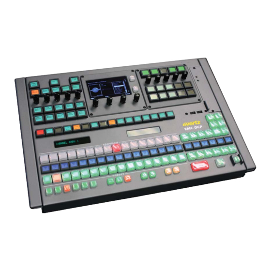
EMC DESKTOP CONTROL PANEL EMC-DCP PHYSICAL DESCRIPTION 3.1. PANEL CONFIGURATIONS The EMC-DCP can be ordered with various options. Figure 3-1 to Figure 3-3 illustrate some of the different configurations for the EMC-DCP. Figure 3-1: Basic EMC-DCP Panel Page 4 Revision 1.1... -
Page 13: Figure 3-2: Emc-Dcp With 2 +Abp Options
EMC-DCP EMC DESKTOP CONTROL PANEL Figure 3-2: EMC-DCP with 2 +ABP options Figure 3-3: EMC-DCP with +LCD and +ABP options Page 5 Revision 1.1... -
Page 14: Emc-Dcp Panel - Top Description
EMC-DCP EMC DESKTOP CONTROL PANEL 3.2. EMC-DCP PANEL - TOP DESCRIPTION Figure 3-4 is used to describe the parts of the EMC-DCP that will be referenced within this installation guide. Figure 3-4: EMC-DCP Top Panel Page 6 Revision 1.1... -
Page 15: Table 3-1: Emc-Dcp - Top Surface Descriptions
Fan Status LEDs: These LEDs indicate the status of the EMC-DCP cooling fans. Cooling Fan unit: This is the cooling fan unit of the EMC-DCP. It can be serviced from the top surface of the EMC-DCP. -
Page 16: Emc-Dcp Panel Input/Outputs
3.3. EMC-DCP PANEL INPUT/OUTPUTS The EMC-DCP has a number of inputs and outputs available. Please note that not all ports will be enabled at this time. Some ports MAY be used for future features. Figure 3-5 shows the inputs and outputs of the EMC-DCP. -
Page 17: Connecting Emc-Dcp To 3025Emc System
EMC-DCP to the EMC, a network hub/switch is required. Connect a Cat 5 Ethernet cable from Ethernet A (on EMC-DCP) to the network hub. The user will then connect a Cat 5 Ethernet cable to the Network Port of the EMC. Use the EMCSetup software to setup the IP addresses, network settings, etc. -
Page 18: Connecting Emc-Dcp To Qmc-2 System
EMC-DCP to the QMC-2, a network hub/switch is required. Connect a Cat 5 Ethernet cable from Ethernet A (on EMC-DCP) to the network hub. The user will then connect a Cat 5 Ethernet cable to the Network Port of the QMC-2. Use the EMCSetup software to setup the IP addresses, network settings, etc. -
Page 19: Configuring Ip Address And Qlink Address Of Emc-Dcp
In order to set the IP Addresses of Ethernet ports A and B and the Q-Link address, the user will be required to enter the Setup Mode of the EMC-DCP, which can be accessed directly on the panel. Figure 3-9 shows which shaft encoders the user MUST push AND simultaneously hold down for 10 seconds in order to enter Setup Mode. -
Page 20: Figure 3-9: Getting Into Emc-Dcp Setup Mode
After about 10 seconds, the EMC-DCP panel will turn RED, and then it will switch to multi-coloured mode. In this mode, the EMC-DCP will display the various Setup Menu options in the top left corner of the panel (see Figure 3-10). -
Page 21: Figure 3-11: Emc-Dcp Setup Menu
Setup Menu. The next row is called the Menu Row. This is the row where the main EMC-DCP parameters are set. Use Shaft Encoder 1 to scroll through the parameters (see Table 3-2) and Shaft Encoders 2 to 5 to set the parameter values. -
Page 22: Setting Up Ethernet Control Using Emc Setup
SETTING UP ETHERNET CONTROL USING EMC SETUP Once the EMC-DCP has been setup, the user must now configure the rest of the EMC system to see the panel. This is done using the QMCSetup (or newer EMCSetup) software tool. The user will first set an IP address for the EMC channel and configure the EMC to send Q-Link packets over Ethernet (select checkbox). -
Page 23: Figure 3-13: Qmcsetup/Emcsetup Windows Application
EMC-DCP EMC DESKTOP CONTROL PANEL Next, the user will configure the EMC-DCP to use Ethernet. The procedure for adding the EMC-DCP is similar to any other QMC-2 control panel. Under the EMC-DCP configuration, the user must set the Q- Link address (matches the one set on the EMC-DCP in section 3.6) and then select the “Ethernet instead of Qlink”... -
Page 24: Figure 3-14: Emc/Qmc-2 Ip Address Window
EMC-DCP EMC DESKTOP CONTROL PANEL Figure 3-14: EMC/QMC-2 IP Address Window The EMC must be rebooted for the IP address change to take effect. Page 16 Revision 1.1... -
Page 25: Figure 3-15: Setting Ip Address Of Emc-Dcp Using Qmcsetup/Emcsetup V4.00
Serial or Ethernet to the EMC channel. Once all the appropriate fields have been entered, the setup is complete. If the IP address of the EMC has not been set, the EMC-DCP setup will not take effect. Page 17... -
Page 26: Testing Emc-Dcp Setup
QMCSetup software. If not, the panel may report No Q-Link Comms. The user should check the Q-Link ID on the EMC-DCP and on the EMC Setup configuration file. -
Page 27: Figure 3-16: Emc-Dcp Layout For Mini Master Control
EMC-DCP EMC DESKTOP CONTROL PANEL Figure 3-16: EMC-DCP Layout for Mini Master Control Page 19 Revision 1.1... - Page 28 EMC-DCP EMC DESKTOP CONTROL PANEL Button Description This button selects the source (from the 12 sources on LCD row below button) for the KEY Input of the PKG9625SW or PKGHD9625SW. It determines what portion of the variable to use, and from what source.
-
Page 29: Upgrading The Emc-Dcp Firmware Using A Usb
3.11. UPGRADING THE EMC-DCP FIRMWARE USING A USB In order to upgrade the firmware on the EMC-DCP, the user will need to download the latest EMC-DCP firmware from the Evertz website (www.evertz.com). The firmware should be transfer onto a USB 2.0 memory stick (onto the top level/root directory). -
Page 30: Figure 3-18: Update Mode Of The Emc-Dcp
The user will see the current firmware in the third row of LCD buttons. The VFD Display 1 will show the firmware versions found on the USB 2.0 Memory stick that is plugged into the EMC-DCP. The user will use the “Refresh” button to update the list. Use the UP or DOWN arrows to scroll the list of available firmware and scroll to the desired firmware release. -
Page 31: Figure 3-19: Confirmation Of The Upgrade
“No”, and they will be returned to Update Mode (see Figure 3-18). If the user selected “Yes”, the EMC-DCP will proceed to install the new update. This will include a panel reset. The process should take about 5 minutes to complete. -
Page 32: Upgrading The Emc-Dcp Firmware Over The Network
To do this you need to connect to the EMC-DCP webpage using the Mozilla Firefox web browser. To confirm that the configuration PC is able to connect to the EMC-DCP simply enter the IP address of the EMC-DCP (either NIC A or NIC B). - Page 33 From the upgrade webpage, click “Browse” to navigate to the location of the “.efp” file that you need to install. Note that there are two different file types. If the EMC-DCP is to be used with a QMC-2/3025 system then the “emcdcp-update-x.x.x.x.efp” upgrade file must be used. If the EMC-DCP is to be used with a PKG9625SW system then the “emcdcp-switcher-update-x.x.x.x.efp”...
-
Page 34: Technical Description
Figure 4-1 to Figure 4-5 shows the overall dimensions of the unit with and without the Desktop mount. Dimensions: 19” W x 5.6” H x 12.8” D. (483mm W x 142mm H x 325mm D) Weight: 8 lbs. (3.5Kg) Figure 4-1: EMC-DCP Front View with Desktop Mount Page 26 Revision 1.1... -
Page 35: Figure 4-2: Emc-Dcp Side View With Desktop Mount
EMC-DCP EMC DESKTOP CONTROL PANEL Figure 4-2: EMC-DCP Side View with Desktop Mount Page 27 Revision 1.1... -
Page 36: Figure 4-3: Emc-Dcp Top View
EMC-DCP EMC DESKTOP CONTROL PANEL Figure 4-3: EMC-DCP Top View Figure 4-4: EMC-DCP Top Side View without Desktop Mount Page 28 Revision 1.1... -
Page 37: Servicing Instructions
EMC-DCP EMC DESKTOP CONTROL PANEL Figure 4-5: EMC-DCP Side View without Desktop Mount 4.2. SERVICING INSTRUCTIONS CAUTION – These servicing instructions are for use by qualified service personnel only. To reduce risk of electric shock, do not perform any servicing instructions in this section of the manual unless you are qualified to do so. -
Page 38: Installing The Emc-Dcp Desktop Mount
EMC-DCP EMC DESKTOP CONTROL PANEL INSTALLING THE EMC-DCP DESKTOP MOUNT When you receive an EMC-DCP, it usually comes without a Desk Mount kit. This option can be added later on. This kit contains the following parts: 1 x EQMC-DCP2-MB-2 (Desktop Mount Bracket LH) - Page 39 EMC-DCP EMC DESKTOP CONTROL PANEL Figure 5-2 shows the side screws that need to be removed and discarded. (A total of 4 screws. Two from each side). Page 31 Revision 1.1...
-
Page 40: Figure 5-2: Side Screws
EMC-DCP EMC DESKTOP CONTROL PANEL Figure 5-2: Side Screws Figure 5-3 shows the top two corner screws at the back of the panel that need to be removed. (A total of 2 screws). Figure 5-3: Top Two Corner Screws at the Back of the Panel Page 32 Revision 1.1... -
Page 41: Desktop Mount Assembly
EMC-DCP EMC DESKTOP CONTROL PANEL Figure 5-4 shows the bottom screws at the back of the panel that need to be removed. (A total of 4 screws). Figure 5-4: Bottom Screws at the Back of the Panel 5.1. DESKTOP MOUNT ASSEMBLY Once all ten screws are removed, you can start assembling the new parts. -
Page 42: Figure 5-6: Bracket Assembly
EMC-DCP EMC DESKTOP CONTROL PANEL Next step is to assemble the two Desktop Mounting Brackets (Part #2 for the left side and Part #8 for the right side). Each side needs 1X M3x8mm 2X M3x12mm and 2X M3xmm screws. In this manual, only the left side bracket assembly will be described (see Figure 5-6). -
Page 43: Figure 5-8: Full Assembly
EMC-DCP EMC DESKTOP CONTROL PANEL Figure 5-8: Full Assembly Page 35 Revision 1.1... - Page 44 EMC-DCP EMC DESKTOP CONTROL PANEL This page left intentionally blank Page 36 Revision 1.1...
Need help?
Do you have a question about the EMC-DCP and is the answer not in the manual?
Questions and answers