Table of Contents
Advertisement
Quick Links
© Copyright 2010 - 2013
EVERTZ MICROSYSTEMS LTD.
5288 John Lucas Drive,
Burlington, Ontario, Canada
L7L 5Z9
Phone:
Sales Fax:
Tech Support Phone:
Tech Support Fax:
Internet: Sales:
Tech Support: service@evertz.com
Web Page:
Version 1.1 July 2013
The material contained in this manual consists of information that is the property of Evertz Microsystems and is
intended solely for the use of purchasers of the CP-2232E. Evertz Microsystems expressly prohibits the use of
this manual for any purpose other than the operation of the device.
All rights reserved. No part of this publication may be reproduced without the express written permission of Evertz
Microsystems Ltd.
Copies of this guide can be ordered from your Evertz products dealer or from Evertz
Microsystems.
CP-2232E
Remote Control Panel
User Guide
+1 905-335-3700
+1 905-335-3573
+1 905-335-7570
+1 905-335-7571
sales@evertz.com
http://www.evertz.com
Advertisement
Table of Contents

Related Manuals for evertz CP-2232E


Summary of Contents for evertz CP-2232E
-
Page 1: User Guide
Version 1.1 July 2013 The material contained in this manual consists of information that is the property of Evertz Microsystems and is intended solely for the use of purchasers of the CP-2232E. Evertz Microsystems expressly prohibits the use of this manual for any purpose other than the operation of the device. -
Page 3: Important Safety Instructions
IMPORTANT SAFETY INSTRUCTIONS The lightning flash with arrowhead symbol within an equilateral triangle is intended to alert the user to the presence of uninsulated “Dangerous voltage” within the product’s enclosure that may be of sufficient magnitude to constitute a risk of electric shock to persons. The exclamation point within an equilateral triangle is intended to alert the user to the presence of important operating and maintenance (Servicing) instructions in the literature accompanying the product. - Page 4 WARNING Changes or modifications not expressly approved by Evertz Microsystems Ltd. could void the user’s authority to operate the equipment. Use of unshielded plugs or cables may cause radiation interference. Properly shielded interface cables with the shield connected to the chassis ground of the device must be used.
- Page 5 Evertz products are for informational use only and are not warranties of future performance, either expressed or implied. The only warranty offered by Evertz in relation to this product is the Evertz standard limited warranty, stated in the sales contract or order confirmation form.
- Page 6 CP-2232E Remote Control Panel This page left intentionally blank Revision 1.1...
-
Page 7: Table Of Contents
4.5. CHECKING THE STATUS OF THE PANEL ................8 5. SYSTEM CONFIGURATION ....................9 5.1. UPGRADING THE CP-2232E PANEL ................... 9 5.1.1. Requirements ......................9 5.1.2. Getting Started ......................9 5.1.3. Upgrading Firmware on the CP-2232E ............... 9 5.2. SYSTEMS MENU ........................ 11 Page i Revision 1.1... - Page 8 5.5.2.1. Visual Settings .................... 34 5.5.3. Import/Export Page ....................35 5.6. UPGRADE MENU ........................ 36 6. ADDING AN EVERTZ SYSTEM TO CONTROL ............... 37 6.1. CP-2232E CONTROL OF MVP SYSTEM ................37 6.2. ADDING SNMP SERVICES ....................39 6.3. ADDING AN EQX SERVER ....................40 6.4.
- Page 9 Figures Figure 1-1: CP-2232E Control Panel ..................... 1 Figure 2-1: CP2232E Rear Panel ....................2 Figure 2-2: CP-2232E Front Control Panel ..................3 Figure 5-1: CP2232e Web Interface ....................9 Figure 5-2: Install Firmware Page ....................10 Figure 5-3: Systems Drop Down Menu ..................11 Figure 5-4: Products Page ......................
- Page 10 CP-2232E Remote Control Panel Figure 6-4: Add EQX Server ......................40 Figure 7-1: Front Panel Display ....................42 Figure 7-2: SRC Layout ....................... 42 Figure 7-3: SRC Keypad Display ....................43 Figure 7-4: DST Layout ....................... 44 Figure 7-5: DST Keypad Display ....................44 Figure 7-6: Up &...
-
Page 11: Overview
SNMP equipment in your facility as well as integrate with router systems. The CP-2232E enables users to have real-time control over a MVP or VIP system, display graphical visualizations of layouts prior to loading them, control what signal is routed to what multiviewer window, select an audio to be monitored, etc. -
Page 12: Installation
CP-2232E Remote Control Panel INSTALLATION 2.1. REAR PANEL Figure 2-1 shows the rear view of the CP-2232E control panel. The following is a list of the ports and controls on the rear panel: SERIAL A SERIAL B JOYSTICK/GPIO ETHERNET A... -
Page 13: Power Connections
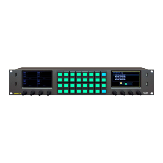
Figure 2-2: CP-2232E Front Control Panel Please note that the labels in Figure 2-2 will NOT be displayed on the front panel of your CP-2232E device. The labels listed above are for reference purposes only when describing the panel controls in the following sections of the manual. -
Page 14: Mounting
2.4. MOUNTING The CP-2232E is equipped with rack mounting angles and fits into a standard 19 inch by 3.5 inch by 1.2 inch (483 mm x 89 mm x 32mm) rack space. Cooling is achieved by passive air flow across and through the panel chassis. -
Page 15: Technical Description
CP-2232E Remote Control Panel TECHNICAL DESCRIPTION 3.1. SPECIFICATIONS 3.1.1. Control Ethernet: 10/100 base T.RJ45 connector Joystick: Parallel contact closure TTL levels, D9 male 3.1.2. Electrical Voltage: Autoranging 100V - 240V AC, 50/60Hz Power: 80 Watts Fuse Rating: 250V, 4A, time delay 3.1.3. -
Page 16: Front Panel Control
FRONT PANEL CONTROL To enter the setup menu of the CP-2232E press and hold the first and last rotary encoders (S1 and S4) on the far left side of the panel for approximately 6 seconds. You will then be presented with several menus which allow testing and configuration of the panel. -
Page 17: Configuring The Network Settings
OR select the Apply soft-key (L20) button. 4. Bonding may be chosen if you wish the CP-2232E to use the same IP address on BOTH Ethernet ports. This setting is ONLY to be used if ONE Ethernet cable is plugged into a single network OR if two completely isolated networks are in use. -
Page 18: Lcd Test
Monitors the time elapse from the initial boot up sequence in hours:minutes:seconds format. • Workload: Monitors the workload. The Reboot option enables the user to restart the system. To shut down the CP-2232E, select the Power Off option. Page 8 Revision 1.1... -
Page 19: System Configuration
“other languages…” option under the download link. 5.1.2. Getting Started 1. Set the IP address of the CP-2232E by holding down the first and last rotary encoders (S1 and S4) on the far left of the panel for 6 seconds. -
Page 20: Figure 5-2: Install Firmware Page
4. If a reboot is required the panel should automatically reboot on its own otherwise you may reboot it using the front panel. 5. Once the panel has rebooted you are ready to configure the CP-2232E. Page 10 Revision 1.1... -
Page 21: Systems Menu
CP-2232E Remote Control Panel 5.2. SYSTEMS MENU The Systems menu enables the user to upload product jar files, create services and templates, and add systems. Figure 5-3 illustrates the Systems drop down menu. Figure 5-3: Systems Drop Down Menu 5.2.1. Products Page The Products page, as illustrated in Figure 5-4, enables the user to upload product jar files to the control panel. -
Page 22: Products Uploaded
The Service Templates page enables the user to create templates that contain SNMP parameters and controls for specific products. These templates are then used for creating and defining SNMP Services on the CP-2232E control panel. The Service Templates page also allows the user to edit existing templates. -
Page 23: Figure 5-6: Service Template List
CP-2232E Remote Control Panel The user can add, copy, or remove a template using the Service Templates buttons listed in Table 5-1: Button Image Description The New Template button enables the user to add and create a new New Template template. -
Page 24: Service Template Controls
CP-2232E Remote Control Panel Figure 5-7: Customizing a Template 5.2.2.1. Service Template Controls To modify the template, use the Service Templates controls as listed below: • Name: To assign a name to the template, enter a unique name into the Name field. -
Page 25: Service Template Parameter Tree
CP-2232E Remote Control Panel • Delete Selected Parameters/Groups: Select the Delete Selected Parameters/Groups to delete a parameter/group. • Add a Group: To add a group to the list, select the Add a Group button. • Hide Tree View: Selecting the Hide Tree View button will hide the parameter tree view. -
Page 26: Template Properties
CP-2232E Remote Control Panel Figure 5-8: Parameter Tree 5.2.2.3. Template Properties The user can adjust the template properties by entering the appropriate information into the fields below: • #: Double-clicking a number in this column will highlight the corresponding parameter in the Service Template Parameter Tree. -
Page 27: Creating A New Service Template
CP-2232E Remote Control Panel • Inc: Entering a number in this field will assign a number value that the encoder will increment when it is rotated. For example, if this value is set to 2, each time the shaft encoder is turned (clicked over once) the value will increment by 2 instead of a regular default unit of 1. -
Page 28: Service Template Controls
The Services page enables the user to create a service or edit an existing service, which can be loaded onto the CP-2232E control panel. Services are created by linking a Service Template to a particular Service and then defining the frame, card in a particular slot, and input using the Services page. -
Page 29: Figure 5-11: Services List
CP-2232E Remote Control Panel Figure 5-11: Services List The user can add, copy, or remove a service using the Service buttons listed in Table 5-2: Button Image Description The New Service button enables the user to add and create a new New Service service. -
Page 30: Service Controls
CP-2232E Remote Control Panel Once a service is selected or the user creates a new service, a new page will appear enabling the user to customize the service. Figure 5-12: Customizing a Service 5.2.3.1. Service Controls To name and save the service, use the Service controls as listed below: •... -
Page 31: Service Properties
5.2.4. Systems Page The Systems page enables the user to view the devices that are currently available on the CP-2232E for connection and control as well as adding new devices. The user can also edit and/or change details, tags, and services for specific devices. -
Page 32: Device Properties
CP-2232E Remote Control Panel The user can add and/or remove a device using the Systems buttons listed in Table 5-3: Button Image Description The New Device button enables the user to add and create a new device. Selecting this button will open a new system window as shown New Device in Figure 5-14. -
Page 33: Discovery Menu
Figure 5-15: Update System Window 5.3. DISCOVERY MENU The Discovery menu, as illustrated in Figure 5-16, enables the user to set the appropriate discovery settings for the panel. The user can also configure the CP-2232E for communication with the VistaLINK Alarm Server. ®... -
Page 34: Settings Page
CP-2232E Remote Control Panel Figure 5-16: Discovery Menu 5.3.1. Settings Page The Settings page enables the user to lock the Discovery system and set the refresh rate of the device. Figure 5-17: Settings Page Lock Discovery: This parameter allows the user to enable or disable the Lock Discovery. If set to On, the Discovery system will not be permitted to add new hardware devices to the list of devices found. -
Page 35: Ranged Discovery Page
CP-2232E Remote Control Panel Auto-Refresh Rate: This parameter allows the user to set the auto-refresh rate of the panel. The minimum refresh rate is 5 seconds. To turn the auto-refresh feature off, enter 0. Select the Save button to save all Discovery settings. -
Page 36: Import Device Labels
CP-2232E Remote Control Panel 5.3.3. Import Device Labels This page enables the user to import device labels in the Navigation Tree from VistaLINK ® Figure 5-19: Import Device Labels Page To import a device label, follow the instructions outlined below: 1. -
Page 37: Vistalink
CP-2232E Remote Control Panel 5.3.4. VistaLINK Alarm Server ® This page enables the user to configure the VistaLINK Alarm Server settings. ® Figure 5-20: VistaLINK Alarm Server ® VistaLINK Alarm Server: This field enables the user to enter the VistaLINK Alarm Server ®... -
Page 38: Source Proc Page
An Alias name for the router source (which will be used if the device name and port are not provided). d. A Service created and saved on the CP-2232E panel. 2. Select the plus sign to create a new mapping. -
Page 39: Destination Proc Page
CP-2232E Remote Control Panel 5.4.2. Destination Proc Page The Destination Proc page enables the user to attach an SNMP service to a router’s output port. Figure 5-23: Destination Proc Page To create a new Destination-Service Mapping, please follow the numbered instructions in section 5.4.1... -
Page 40: Help Menu
CP-2232E Remote Control Panel 1. Select the plus sign to create a new Macro mapping. 2. Enter the name of the desired SNMP service in the Service Name field. 3. Enter the name of the Macro in the Macro Name field. -
Page 41: Panel Version
CP-2232E Remote Control Panel 5.5.1.1. Panel Version Selecting the Panel Version option, as illustrated in Figure 5-26, will display the current panel’s version number. 5.5.1.2. Product Support The Product Support option provides a list of current product versions. Figure 5-27: Product Support Tab Clicking the Product Versions text will reveal a list of currently supported products and their version numbers. -
Page 42: Figure 5-28: Configuration Tab
CP-2232E Remote Control Panel Figure 5-28: Configuration Tab Select the Export Configuration text and an Opening config.cf dialog box will be appear which will prompt the user to open or save the configuration file. Figure 5-29: Opening config.cf Dialog Box Page 32 Revision 1.1... -
Page 43: Logs Tab
CP-2232E Remote Control Panel 5.5.1.4. Logs Tab The Logs tab, as illustrated in Figure 5-30, enables the user to retrieve configuration logs. Figure 5-30: Logs Tab Select the Download Logs text and an Opening logs.lf dialog box will appear which will prompt the user to open or save the log file. -
Page 44: Preferences Page
CP-2232E Remote Control Panel 5.5.2. Preferences Page The user can select the Preferences option from the Help menu drop down menu. The Preferences page enables the user to change the visual settings of the panel. Figure 5-32: Preferences Page 5.5.2.1. -
Page 45: Import/Export Page
CP-2232E Remote Control Panel 5.5.3. Import/Export Page The user can select the Import/Export option from the Help menu drop down. This page, as illustrated in Figure 5-33, enables the user to import and export an advanced panel configuration. Figure 5-33: Import/Export Page To import a configuration, follow the instructions outlined below: 3. -
Page 46: Upgrade Menu
Remote Control Panel 5.6. UPGRADE MENU The Upgrade menu enables the user to upgrade the firmware on the CP-2232E panel. Select the Upgrade menu and the Install Firmware page will open as illustrated in Figure 5-34. Figure 5-34: Install Firmware Page For instructions on how to upgrade the panel’s firmware, please refer to section 5.1.3. -
Page 47: Adding An Evertz System To Control
6.1. CP-2232E CONTROL OF MVP SYSTEM Controlling an MVP system from the CP-2232E panel requires a few “one time” steps (as well as a normal procedure) to be completed on the MVP system prior to working with the CP-2232E: 1. Set up the MVP system to allow control from the CP-2232E. (This step should only be performed once upon initial setup): a. -
Page 48: Figure 6-2: Create A Mvp System
Select one of the layouts and then select the load button. d. The user can also change sources on the CP-2232E. This will allow you to pick a source that is already located on the MVP somewhere else, without making routes. The user can select which audio to route to the monitor outputs. -
Page 49: Adding Snmp Services
CP-2232E Remote Control Panel 6.2. ADDING SNMP SERVICES This section will guide the user through the set up of SNMP services. SNMP services are parameters from one or several pieces of terminal equipment that you wish an operator to control from the CP- 2232E panel. -
Page 50: Adding An Eqx Server
ADDING AN EQX SERVER All router management of the CP-2232E for use in an EQX Server based system is done through the EQX Server WCT (web config tool). Please see the EQX Server manual for details on working with the CP-223E panel in that respect. -
Page 51: Creating Source-Service Mapping
In this way, SNMP Services (and therefore Terminal gear parameters) can be accessed from within the EQX Server portion of the CP-2232E and users do not have to filter through long lists looking for the correct Service name. For more information on Mapping, please refer to section 5.4. -
Page 52: Navigating The Control Panel
NAVIGATING THE CONTROL PANEL Figure 7-1: Front Panel Display The default router control view of the CP-2232E features two touch LCD screens with a maximum of four destinations per screen displaying the following information: Destination Name, Current Source Name, Next Source Name, Profile Selected Name, Destination Page, and State of the Destination (Lock/Protected/etc). -
Page 53: Figure 7-3: Src Keypad Display
The Alpha-Numeric button when pressed will allow the user to type the name of the required source in the Left screen. As the user types the CP-2232E will automatically filter the source list to display any source that matches the characters typed. If a character is typed incorrectly the DEL button can be used to delete the characters. -
Page 54: Destination (Dst) Button
The Alpha-Numeric button when pressed will allow the user to type the name of the required destination in the Left screen. As the user types the CP-2232E will automatically filter the destination list to display any destination that matches the characters typed. If a character is typed incorrectly the DEL button can be used to delete the characters. -
Page 55: Up & Down Arrows
CP-2232E Remote Control Panel button is used to confirm the choice and return the user to Eight Destination view. The selected destination will be automatically selected in the Eight Destination view. The quadrant view in the bottom of the Left display will show the user where the destination will appear when returning to the Eight Destination view. -
Page 56: Clear Next Source Button
CP-2232E Remote Control Panel 7.4. CLEAR NEXT SOURCE BUTTON Figure 7-7: Clear Next Source Button The Clear Next SRC button allows the user to clear the pending or preset source for a selected destination. Page 46 Revision 1.1... -
Page 57: Level Button
CP-2232E Remote Control Panel 7.5. LEVEL BUTTON Figure 7-8: Level Button Display The Level button when pushed will allow the user to enable or display specific levels for a destination. This could be an audio level or video level thereby allowing the user to accomplish a Breakaway route. -
Page 58: Figure 7-10: Select The All Button
CP-2232E Remote Control Panel Figure 7-10: Select the ALL Button The Select ALL or None button will toggle the level state of the levels for the selected destination. If levels have been disabled the associated level buttons will turn Red and the Right screen will not show the Green X for those levels. -
Page 59: Selecting The "More" Button
CP-2232E Remote Control Panel 7.6. SELECTING THE “MORE” BUTTON Figure 7-12: Selecting the “MORE” Button The More button when selected will display the following button selections, Change Profile, Info, Tielines, Back, Toggle, Lock Destination, Protect Destination, One Destination View and Salvo. -
Page 60: Figure 7-14: Selecting The "Info" Button
CP-2232E Remote Control Panel Figure 7-14: Selecting the “INFO” Button The INFO button when selected will display information for the selected Destination, DST, Port, Source, Lock/Protect Owner Information on the Left screen and Level, Source and Next Source information on the Right Screen. The Back button can be used to return to the Eight Destination view. -
Page 61: Figure 7-16: Selecting The "Enable Toggle" Button
CP-2232E Remote Control Panel Figure 7-16: Selecting the “ENABLE TOGGLE” Button Selecting the Enable Toggle button will either enable or disable toggle for the selected destination. When Toggle is enabled the Current Source and Next Source for a destination will flip with each Take button press. -
Page 62: Figure 7-18: Selecting The "Protect" Button
CP-2232E Remote Control Panel Figure 7-18: Selecting the “PROTECT” Button The PROTECT button when pressed will toggle between Protecting or Un-protecting the selected destination. A destination that is protected will display a Shield icon in the top right corner of the destination quadrant. -
Page 63: Figure 7-20: Selecting The "One Dst View" Button
The Alpha-Numeric button when pressed will allow the user to type the name of the required source in the Left screen. As the user types the CP-2232E will automatically filter the source list to display any source that matches the characters typed. If a character is typed incorrectly the DEL button can be used to delete the characters. -
Page 64: Figure 7-22: Selecting The "Toggle Take" Button
CP-2232E Remote Control Panel The TAKE button whether in Eight Destination View or One Destination View when pressed will route the selected source to the selected destination. When a TAKE operation is available the TAKE button will appear PINK. If a TAKE failed because of an error, the button will appear RED, by selecting the MORE button and then VIEW ERROR the user can view details concerning the failure.
Need help?
Do you have a question about the CP-2232E and is the answer not in the manual?
Questions and answers