
Related Manuals for Druck PACE1000


Summary of Contents for Druck PACE1000
- Page 1 PACE Indicators Pressure Automated Calibration Equipment Instruction Manual Druck.com...
- Page 3 The equipment must be maintained using the procedures in this publication. Further manufacturer’s procedures should be done by an authorized service agents or the manufacturer’s service departments. Druck.com Technical Advice For technical advice contact the manufacturer. A qualified technician must have the necessary technical knowledge, documentation, special test equipment and tools to carry out the required work on this equipment.
- Page 4 Do not dispose of this product as household waste. Use an approved organization that collects and/or recycles waste electrical and electronic equipment. For more information, contact one of these: - Our customer service department: Druck.com - Your local government office. WARNING Turn off the source pressure(s) and carefully vent the pressure lines before disconnecting or connecting the pressure lines.
- Page 5 Gauge GPIB General purpose interface bus Water Mercury Hertz IDOS Intelligent Digital Output Sensor (Druck product) i.e. That is IEEE 488 Institute of Electrical and Electronic Engineers standard 488 (for programmable devices with a digital interface) Inch Copyright 2010 Baker Hughes Company.
- Page 6 Transmit data Unit Under Test Volts °C Degrees Celsius °F Degrees Fahrenheit Associated Publications The following table lists the Druck publications referenced in this manual: Publication Title K0467 PACE Indicator User Guide and Safety Instructions K0469 PACE Heritage Communications Manual K0450...
-
Page 7: Table Of Contents
Contents Description Introduction Installation Package Contents Packaging for Storage or Transportation Preparation for Use Connecting to PACE 2.4.1 Pressure Adaptors 2.4.2 Pressure Connection Connecting to UUT 2.5.1 Pneumatic Connection 2.5.2 Hydraulic Connection Mounting Kits 2.6.1 Rack-mount Option 2.6.2 Panel-mount Option Power Connection Communication Connection 2.8.1... - Page 8 Standard Serviceability Test Ethernet Testing 5.3.1 Ethernet Ports 5.3.2 Ping Test 5.3.3 Web Browser Test 5.3.4 Measurement & Automation Explorer Test Fault Finding Approved Service Agents Reference Installation Notes Reference Port Measure Setup 6.3.1 Pressure Zero 6.3.2 Process 6.3.3 Task 6.3.4 Units 6.3.5...
- Page 9 Appendix A. Pressure Units and Conversion Factors Appendix B. Air Density Appendix C. User Interface Icons Copyright 2010 Baker Hughes Company. English–PACE Indicators Instruction Manual | vii...
- Page 10 Copyright 2010 Baker Hughes Company. viii | PACE Indicators Instruction Manual–English...
-
Page 11: Description
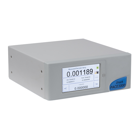
• Panel mount using the panel-mount option kit. Figure 1-2: PACE1000 Rear View Options available for the PACE1000 refer to the Data Sheet. For information and notes on applications, refer to Section 6, “Reference,” on page 35 or Druck.com Copyright 2010 Baker Hughes Company. - Page 12 Chapter 1. Description Copyright 2010 Baker Hughes Company. 2 | PACE Indicators Instruction Manual–English...
-
Page 13: Installation
2.1 Package Contents INFORMATION After unpacking a cold instrument, allow time for it to stabilize and any condensation to evaporate. Check that the PACE1000 packaging contains the following: PACE1000 Pressure Indicator. Power supply adaptor. iii. Safety instructions, instruction manual and CD-ROM containing the full documentation suite. -
Page 14: Pressure Adaptors
Chapter 2. Installation 2.4.1 Pressure Adaptors Figure 2-1 shows the available range of PACE pressure adaptors. IO-SNUBBER-1 IO-DIFFUSER-1 IO-ADAPT-7/16UNF IO-ADAPT-9/16AUTOC IO-ADAPT-G1/4 IO-ADAPT-AN4 IO-ADAPT-1/8NPT IO-ADAPT-AN6 IO-ADAPT-BARB IO-ADAPT-1/4NPT Figure 2-1: Pressure Adaptors Refer to Table 2-1 and the Data Sheet for more information. Table 2-1: Pressure Adaptor Specification Adaptor Part Number Specification... -
Page 15: Pressure Connection
Connecting to PACE 2.4.2 Pressure Connection WARNING Parallel threads must be used. Female thread type is parallel thread to ISO228/1 (DIN ISO228/1, JIS B0202) G1/8. Tapered threads not allowed. The PACE has parallel thread pressure connectors. Use only the connector type specified in Table 2-2. -
Page 16: Connecting To Uut
Chapter 2. Installation For pressures less than 100 bar (1450 psi), see alternative sealing method in Figure 2-3. 1 PACE pressure connector. 2 Bonded seal. 3 ISO228/1 G1/8 pressure connector or adaptor. For adaptors, see Section 2.4.1. Figure 2-3: Alternative Sealing Method for < 100 bar (1450 psi) 2.5 Connecting to UUT The pressure should not exceed 1.25 x full-scale or MWP stated on the rear panel of the instrument. -
Page 17: Hydraulic Connection
Mounting Kits 2.5.2 Hydraulic Connection WARNING Hydraulic liquid is dangerous. Observe relevant health and safety precautions. Use appropriate protective barriers and eye protection. Before applying pressure, examine all fittings and equipment for damage and ensure that all equipment is to the correct pressure rating. Do not exceed the maximum working pressure of the instrument. -
Page 18: Panel-Mount Option
Chapter 2. Installation instrument. The cooling air of the instrument must not be obstructed. Allow a free flow of air through the equipment rack and around the instrument, especially at high ambient temperatures. Figure 2-4: Rack-mounting Locate instrument in rack mount assembly (1). Secure with the four M3 x 6 screws (2), (maximum length M3 x 8). - Page 19 Mounting Kits The cooling air of the instrument must not be obstructed. Allow a free flow of air through the equipment rack and around the instrument, especially at high ambient temperatures. Figure 2-5: Panel-mounting Remove the four screws (1) from the instrument. Locate the instrument in panel mount assembly.
-
Page 20: Power Connection
Isolate the power supply before making any electrical connections to the rear panel. CAUTION Use the power adaptor supplied with the instrument (Druck part number IS1000118M9922-12). Using other power adaptors may cause over- heating, this can result in a fire. -
Page 21: Rs-232 Interface
Communication Connection Note: Refer to the Data Sheet for a list of optional communication ports. CONSULT HANDBOOK ANALOGUE 1 22V to 26V Power supply adaptor. RS-232 IEEE 488 USB B USB A Ethernet Figure 2-6: Communication Connectors 2.8.1 RS-232 Interface When using the RS-232 interface, a cable must be connected directly from the instrument to a suitable port on the computer in a ‘point to point’... -
Page 22: Ieee 488 Interface
2.8.2 IEEE 488 Interface The interface complies with IEEE 488 standard. The IEEE 488 parallel interface connects a computer/controller to one or more PACE1000 instruments and other instruments. Up to 30 instruments can be connected through a high-speed data bus to the computer/controller. - Page 23 Communication Connection Figure 2-7: IEEE 488 Connection Copyright 2010 Baker Hughes Company. English–PACE Indicators Instruction Manual | 13...
- Page 24 Chapter 2. Installation Copyright 2010 Baker Hughes Company. 14 | PACE Indicators Instruction Manual–English...
-
Page 25: Operation
Preparation 3. Operation This section contains quick reference charts detailing all the available functions and the setup menu. 3.1 Preparation Make sure the electrical cables and pneumatic pipes (tubes) comply with the installation requirements. Refer to Section 2, “Installation,” on page 3. Before use do the following: If necessary, do the maintenance task. -
Page 26: Measure Mode
Chapter 3. Operation 3.3 Measure Mode 1 Pressure reading 2 Functions enabled 3 Zero key (vent system before starting zero sequence) 4 Function area 5 Status area 6 Current pressure range Figure 3-1: Touch Screen Areas Table 3-1: Display Icons Icon Description Icon... - Page 27 Measure Mode Function area Min/Avg/Max is performed on the reading selected for display in the top screen. The Ethernet LAN Status indication (1) shows the following: • Color red - not connected • Color green - connected Copyright 2010 Baker Hughes Company. English–PACE Indicators Instruction Manual | 17...
-
Page 28: Data Logging
Chapter 3. Operation Selecting P1-P2 condition for display in the lower function area of the display allows the display of the subtraction of the middle status area displayed pressure P2 from upper most displayed pressure P1, or selecting P2-P1 condition for display in the lower function area of the display allows the display of the subtraction of the upper most displayed pressure P1 from the middle status area displayed pressure P2. - Page 29 Data Logging Copyright 2010 Baker Hughes Company. English–PACE Indicators Instruction Manual | 19...
- Page 30 Chapter 3. Operation Copyright 2010 Baker Hughes Company. 20 | PACE Indicators Instruction Manual–English...
-
Page 31: Measure Menu Setup
Operation and Example Procedures 3.4.1 Measure Menu Setup Measure set-up Pressure zero current pressure reading to zero, offset stored for current range. Range allows selection of available pressure ranges. Process Filter pressure reading Tare Peak Task Units select from list of available pressure measurement units. -
Page 32: Task
Chapter 3. Operation 3.5.3 Task Pressing Task enables pre-determined functions: Task Basic Airfield Option refer to data sheet Return to home. Selecting a task exits the menu and Exit set-up. changes the display to the task selected. The display shows the task screen, see illustration above. When selected, e.g. -
Page 33: Leak Testing Option
Operation and Example Procedures QNE QNH QFE Runway on Earth’s surface. 29.9212 inHg (1013.25 hPa) datum. Sea level reference datum (adjusted). Figure 3-2: Q Code Visualization 3.5.4 Leak Testing Option This task, measures the leak rate over the measure dwell time. At the start of the test, the instrument measures the test pressure of the user system. -
Page 34: Global Setup Selections
Chapter 3. Operation On completion, the display shows the leak rate results with leak rate per second or per minute in the current pressure units selected in measure setup. Leak test Start Settings Test time /second Leak rate /minute 3.6 Global Setup Selections Global setup selections provide access to the instrument‘s settings for both measure and control modes. -
Page 35: Supervisor Setup, Calibration, Save/Recall User Setup And Display
Global Setup Selections 3.6.1 Supervisor Setup, Calibration, Save/Recall User Setup and Display Selections Escape Key Global set-up Supervisor set-up Calibration PIN - enter four digit code (4321) Save current user set-up Save/recall user set-up Recall current user set-up Resolution - Measure display resolution Display Back light - % brightness... -
Page 36: Supervisor Setup
Chapter 3. Operation 3.7 Supervisor Setup The supervisor setup menu provides facilities for changing settings. These are made during installation. Supervisor Pressing the escape key stores settings and returns to global set-up. enter four digit code (0268) Enable/disable high pressure Alarms Enable/disable low pressure IEEE488... -
Page 37: Instrument Status
Instrument Status 3.8 Instrument Status The control setup menu provides access to the status of the instrument: Pressing the escape key Instrument Status stores settings and returns to global set-up. Instrument Software installed Instrument Main Code Additions to the Hardware build Instrument OS Build standard instrument Instrument Boot ROM... -
Page 38: Software
Chapter 3. Operation 3.9 Software Software history, in the status menu, provides read only information on the current software in the instrument. Software history Instrument Main Code Instrument OS Build Instrument Boot ROM Example Additional selections for options enabled: Analgue etc. Analogue O/P Main Code Analogue O/P Boot ROM Exit set-up. -
Page 39: Maintenance
Insert a USB memory device into a web connected PC. Open Windows Explorer and select the USB memory device root folder. Delete the following folders if they are present: Using a web browser go to the following Druck PACE support page: https://www.bakerhughesds.com/download-center?bh_ref=gemeasurement.com Copyright 2010 Baker Hughes Company. - Page 40 Chapter 4. Maintenance In the search window, select the following and hit Apply: Search Term Entry Industry (leave blank) Category Pressure Controllers - PACE Product Select PACE5000 or PACE6000 Name (leave blank) Select the software history file and open this file. Read this file to become aware of the latest and previous software version and any particular fixes needed.
-
Page 41: Testing And Fault Finding
Introduction 5. Testing and Fault Finding 5.1 Introduction This section details the standard serviceability test. Table 5-2 on page 33 lists possible faults, and the response. The PACE contains a self-test and diagnosis system that continuously monitors the performance of the instrument. At power-up, the system performs a self-test. 5.2 Standard Serviceability Test CAUTION Always release pressure before disconnecting pressure... -
Page 42: Web Browser Test
Chapter 5. Testing and Fault Finding Using the “ping” command, ping the PACE IP address. See the screen capture below. The PACE will reply if operating correctly. Note: The ping command example shows an IP address 3.115.21.237. The IP address of your PACE may be different. -
Page 43: Fault Finding
Fault Finding Navigate to My System > Devices and Interfaces > Network Devices Select the PACE1000 device. The PACE home page will be displayed if operating correctly. 5.4 Fault Finding Check the faults and responses, refer to Table 5-2. If the fault persists, refer to Section 5.5. - Page 44 Chapter 5. Testing and Fault Finding Copyright 2010 Baker Hughes Company. 34 | PACE Indicators Instruction Manual–English...
-
Page 45: Reference
Installation Notes 6. Reference 6.1 Installation Notes The PACE1000 pressure indicator requires a set of connections with the exception of the reference connection, this provides a reference to atmosphere for gauge sensors and barometric sensors. The gas density and type does not affect the accuracy of pressure measurement, assuming that the UUT is at the same level (height) as the indicator or gas head correction is accurately set. -
Page 46: Task
Chapter 6. Reference 6.3.3 Task Selecting Task enables a set of pre-determined functions and software enabled optional functions. 6.3.4 Units Select the new units from the list of pressure measurement units. Special units can also be defined. Refer to Section 6.6.6, “User Defined Units,” on page 50. 6.3.5 Global Setup Refer to Section 6.5, “Global Setup,”... -
Page 47: Global Setup
6.6.2 Communications Selects a communication port parameter. Simultaneous operation of the RS-232, IEEE 488 and Ethernet interfaces is fitted as standard. Note: PACE1000 Lab view drivers are available for download from: http://sine.ni.com/apps/utf8/niid_web_display.download_page?p_id_guid=B6F9A6B06A EA01F1E0440021287E65E6 The user can select appropriate settings for communicating with the control computer (PC) and the required command protocol. - Page 48 Chapter 6. Reference Referring to the PACE SCPI communications user manual, there are three commands that can be used to retrieve pressure readings from the PACE100X: :INST:SENS[x]:READ? Where x = 1 to 8 set in the comms range menu. :SENS:PRES? Returns the reading top main display window with display filtering (2 Hz update rate) applied.
- Page 49 Note: The factory set Supervisor PIN is 0268. If the Supervisor PIN has been locally changed, make sure that the new PIN is kept in a safe place. If the new PIN is lost, it can only be reset at a Druck Service Centre. On the SUPERVISOR screen, select COMMS.
- Page 50 Chapter 6. Reference 6.6.2.2 IEEE 488 Located on the rear panel an external IEEE 488 connection has the following configuration: Table 6-1: IEEE 488 Configuration Options Item Description Connector 24-way ‘D’ female wired as IEEE 488 standard. Communications IEEE 488 GPIB Default Address Protocols SCPI...
- Page 51 Supervisor Setup To configure the RS-232 connection: Navigate to the supervisor communications configuration. Refer to Section 6.6.2.1, “Navigating to Communications Menu,” on page 38. On the COMMUNICATIONS screen, select RS232. On the RS232 PARAMETERS screen, use the Up and Down arrows to highlight and edit the desired parameter.
- Page 52 Chapter 6. Reference On the USB PARAMETERS, use the Up and Down arrows to highlight and edit the desired communications mode. 6.6.2.5 Ethernet Located on the rear panel an external Ethernet connection has the following configuration: Table 6-4: Ethernet Configuration Options Item Description Connector...
- Page 53 Supervisor Setup On the COMMUNICATIONS screen, select ETHERNET. On the ETHERNET PARAMETERS, use the Up and Down arrows to highlight the desired parameter. To change the ADDRESS parameter, complete the following: On the ETHERNET PARAMETER screen, use the UP and DOWN arrows to highlight the ADDRESS field.
- Page 54 Chapter 6. Reference Press the top touch pad on the screen to set the new address type. The screen automatically returns to the ETHERNET PARAMETERS screen. To change the host name, complete the following: On the ETHERNET PARAMETER screen, use the UP and DOWN arrows on the right of the screen to highlight the HOST NAME field.
- Page 55 Supervisor Setup Press the top touch pad on the screen to enter the WEB PASSWORD screen. The keyboard screen opens. Use the keyboard to input the new web password and then press the top touch area on the screen to set the new password. The screen automatically returns to the ETHERNET PARAMETERS screen.
- Page 56 Chapter 6. Reference Use the UP and DOWN arrows to highlight the desired setting. The setting is either ON or OFF. Press the top touch pad on the screen to set the new setting. To change ACCESS MODE, complete the following: On the ETHERNET PARAMETER screen, use the UP and DOWN arrows on the right of the screen to highlight the ACCESS CONTROL field.
- Page 57 Supervisor Setup Use the UP and DOWN arrows to highlight the required parameter. The choices are OPEN or RESTRICTED. Press the ACESS MODE OPEN or ACCESS MODE RESTRICTED touch pad at the top of the screen to set the required access mode. 10.
- Page 58 Chapter 6. Reference Use the number touch pad at the bottom of the screen to input the new IP address and press the CONTROLLER IP ADDRESS touch pad at the top of the screen to set the new IP address. 11.
- Page 59 Supervisor Setup In the Comms Range value configuration, they are assigned the following ranges: • Range 1 = 1150 mbar a • Range 2 = Barometric sensor • Range 3 = 2 bar g When communicating with the PACE, to request a pressure reading from the 1150 mbar a sensor, the SCPI command requests a reading from Index 1.
-
Page 60: Gas Head Correction
Note: Confirmation of the new PIN permanently replaces the old PIN. Record this new PIN and keep in a safe place. If new PIN is lost it can only be reset by returning the instrument to a Druck service center. - Page 61 Create a language file by translating from the English language file. Check the pixel width of each translated word by using the PACE language check file. This can be downloaded from the Druck Support Central. Create an empty DPI folder on a USB stick.
-
Page 62: Restore As Shipped Settings
Chapter 6. Reference Note: An English and French language file name would be: LanguageEnglish.lng and LanguageFrench.lng. Language files named “Language.lng” or in any other format will be ignored by PACE. Figure 6-1: Language Setting 6.6.9 Restore as Shipped Settings Restores instrument settings to factory default. Note: Does not affect PIN settings. -
Page 63: Screen Calibration
Note: Confirmation of the new PIN permanently replaces the old PIN. Record this new PIN and keep in a safe place. If new PIN is lost it can only be reset by returning the instrument to a Druck service center. For more information regarding calibration, refer to PACE Calibration Manual K0450. -
Page 64: Analog Output Option
Chapter 6. Reference 6.9.2 Analog Output Option The Analog Output option provides an analog output that is proportional to measured pressure. CONSULT HANDBOOK Selects Analogue ANALOGUE 1 ANALOGUE 2 22V to 26V Output Range analogue connections 30V maximum with respect to chassis. -
Page 65: Volts-Free Contact Option
Installation and Ancillary Equipment Kit 6.9.3 Volts-free Contact Option The Volts-free Contact option provides a selectable relay contact toggle depending on conditions set in the PACE instrument. Each selection has CONSULT HANDBOOK three Volts-free ANALOGUE 1 ANALOGUE 2 Contacts. 22V to 26V volts-free connections 30V maximum with respect to 30Vmax... -
Page 66: Return Goods/Material Procedure
Service by unauthorized sources will affect the warranty and may not guarantee further performance. You must inform Druck if the product has been in contact with any hazardous or toxic substance. The relevant COSHH or in the USA, MSDS, references and precautions to be taken when handling. - Page 67 Appendix A. Pressure Units and Conversion Factors Pressure Units Factor (hPa) Pressure Units Factor (hPa) mbar O @ 20°C 0.978903642 1000.0 O @ 20°C 97.8903642 0.01 0.0980665 Pa (N/m kg/m 980.665 kg/cm 10.0 torr 1.333223684 10000.0 1013.25 mmHg @ 0°C 1.333223874 68.94757293 cmHg @ 0°C...
- Page 68 Appendix A. Pressure Units and Conversion Factors Copyright 2010 Baker Hughes Company. 58 | PACE Indicators Instruction Manual–English...
- Page 69 Appendix B. Air Density Values of air density (kgm ) for air of relative humidity 50% and containing 0.04% carbon dioxide by volume. Table B-1: Air Density Values Air Temperature (°C) Pressure (kPa) 1.052 1.045 1.037 1.029 1.021 1.014 1.006 1.064 1.057 1.049...
- Page 70 Appendix B. Air Density Copyright 2010 Baker Hughes Company. 60 | PACE Indicators Instruction Manual–English...
- Page 71 Appendix C. User Interface Icons The following icons are used in the PACE series of instruments. Not all icons are used in every PACE instrument. Display Icons in Setup Menus Icon Function Icon Function Icon Function Active Aero setup Aeronautical Airspeed range Alarm Altitude range...
- Page 72 Appendix C. User Interface Icons Display Icons in Setup Menus Icon Function Icon Function Icon Function Escape Ethernet Ethernet not connected Ethernet connected Exclamation Fault history Gas head pressure Gauge mode Global setup Go-to-ground Hardware build Home Idle time-out IEEE 488 Information In limits Instrument...
- Page 73 Display Icons in Setup Menus Icon Function Icon Function Icon Function Save as shipped Save recall user setup Save user setup settings Screen mode Screen saver Select range Set-point disable/enable Set-point limits Set-point higher limit Set-point lower limit Set date Set serial number Set time Setup zero...
- Page 74 Appendix C. User Interface Icons Copyright 2010 Baker Hughes Company. 64 | PACE Indicators Instruction Manual–English...
- Page 76 India Japan Toulouse Pune Tokyo +33 562 888 250 +91-2135-620421~425 +81 3 3531 8711 sensing.FR.cc@bakerhughes.com mcindia.inhouseservice@bakerhughes.com service.druck.jp@bakerhughes.com Abu Dhabi Leicester Billerica +971 2 4079381 +44 (0) 116 2317107 +1 (281) 542-3650 ...
Need help?
Do you have a question about the PACE1000 and is the answer not in the manual?
Questions and answers