Table of Contents
Advertisement
Quick Links
Advertisement
Table of Contents

Related Manuals for jbc DMP


Summary of Contents for jbc DMP
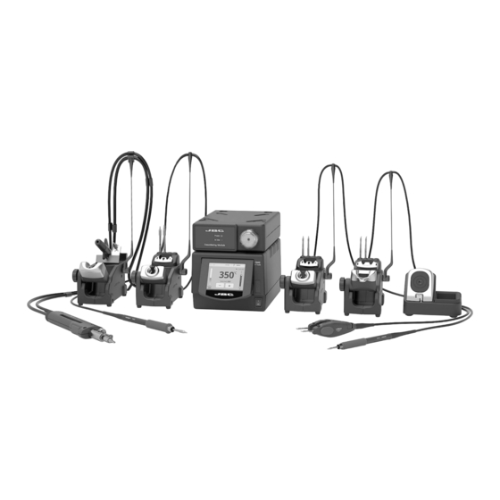
- Page 1 INSTRUCTION MANUAL 4-Tool DMU Precision Rework & Desoldering Station...
-
Page 2: Table Of Contents
Packing List The following items are included: DME Control Unit ..1 unit Electric Desoldering ESD Tip Cleaner .... 1 unit Ref. DMU-1A (120V) Module ......1 unit Ref. CL8499 DMU-2A (230V) Ref. MSE-A DMU-9A (100V) Stand ........2 units Stand ......... 1 unit Stand ......... - Page 3 w w w.jbctools.com DR560 Accessories Ref. 0022819 Tip cleaning set ........1 unit Long Tip Cleaning set ......1 unit Ref. 0965970 Ref. 0965760 Glass solder collector ......1 unit Spanner ............ 1 unit Ref. 0812620 Ref. 0780550 Filter Box ....1 unit Internal gasket ..
-
Page 4: Stand
Connections Stand Cable Equipotential connection Ref. 0011283 RJ45 connector for LAN USB-B connector RJ12 connector for Robot or Smart Fume Extractors RJ12 connector for PSE Power Socket General Purpose Handle Desoldering Iron Ref. T245-A Ref. DR560-A Stand Stand Ref. AD-SE Ref. -
Page 5: Electric Desoldering Module
w w w.jbctools.com Adjustable Precision Micro Purpose Tweezers Handle Ref. AM120-A Ref. T210-A Stand Stand Ref. AD-SE Ref. AM-SA Module Cable Ref. 0014874 Electric Desoldering Module Ref. MSE-A To another peripheral To Pedal Ref. P-405 Suction Filter Ref. 0821830... - Page 6 Features 3.5” Color TFT Touch screen USB-A connector Tilt the display for easy reading Main Switch Work Screen The DME-A offers an intuitive user interface which provides quick access to the station parameters. Default PIN: 0105 Station Information Help for each parameter Station Lock Cartridge 17:14...
- Page 7 Insert a USB flash drive into the USB-A connector to save your soldering process in csv format. Files Station update Download the JBC Update File from www.jbctools.com/software.html Insert the USB flash drive with the file downloaded to the station. Update...
- Page 8 MSE / Pedal Initial Setup After connecting the electric desoldering module (MSE-A), a popup window is opened. Peripherals 17:14 17:14 Peripherals Peripherals Port Port MS a MS a PERIPHERAL PD a Peripheral 1 plugged: Electric Suction Module Setup Postpone 1. To configure your Electric Suction Module 2.
- Page 9 4. Press Menu or Back to save changes. Once set up, you can change the module settings by entering the Peripherals Menu. w w w.jbctools.com Cartridge Adjustment Insert the cartridge model and the station will 17:14 recognize its characteristics (size and shape) to provide better temperature precission.
- Page 10 Operation The JBC Most Efficient Soldering System Our revolutionary technology is able to recover tip temperature extremely quickly. It means the user can work at a lower temperature and improve the soldering quality. The tip temperature is further reduced thanks to the Sleep and Hibernation modes which increase up to 5 times the life of the tip.
- Page 11 w w w.jbctools.com Desoldering process Use a tip with a larger diameter than the pad to achieve maximum aspiration and thermal efficiency. 1. Placing 2. Rotating 3. Aspirating 4. Removing Place the tip over the When the solder Press and hold the Remove the tip lead.
- Page 12 Changing Grips* Replace the soft foam grips easily using the slip-on tabs. Note: Choose the correct grip depending on your handle model. D-Q: D-Q: Handles Green grips Blue grips Black grips T210, T210P, T210N T8658 T3310 T3311 T245, T245G, T245P T6057 T1528 T1530...
- Page 13 w w w.jbctools.com Quick Tip Changer Save time and change cartridges safely without switching the station off. Be careful, the cartridges may be hot, when placing them in the storage rack. 1. Removing 2. Inserting 3. Fixing Place the cartridge in the Place the handle on top Use the holes to fix the extractor and pull the handle...
- Page 14 AM120 Changing cartridges 1. Removing 2. Positioning Place the cartridges in the extractor and pull Place the tweezers on top of the new cartridge the tweezers to remove them. and slightly press down. 3. Inserting *Important It is essential to insert the cartridges as far as the mark for a proper connection.
- Page 15 w w w.jbctools.com MSE Changing the pump filters 17:14 T245 - Keep the casing clean by using a damp cloth. Periodically check all cable and tube connections. ºC - Keep filters clean to ensure proper solder suction and replace them when necessary. 17:14 Temp.
- Page 16 Glass Solder Collector Cleaning 1. Removing the lid 2. Cleaning Check internal joint Remove the coil and clean the inside of the glass solder collector with the cleaning stick. Check filter 17:14 17:14 T245 T245 ºC ºC The lid must be unscrewed with the DR560 in Check the filter and replace it if it is dirty a vertical position.
- Page 17 w w w.jbctools.com CLM Features Improve thermal transfer by cleaning the tip after each solder joint. Brass wool Ref. CL6210 Sponge Very effective cleaning Ref. S0354 method. It leaves a small layer of solder on the tip to The least harmful prevent oxidation between cleaning method.
- Page 18 If necessary use a tool to lever it off. and replace it in the station. - Replace any defective or damaged pieces. Use original JBC spare parts only. - Repairs should only be performed by a JBC authorized technical service.
- Page 19 w w w.jbctools.com Safety It is imperative to follow safety guidelines to prevent electric shock, injury, fire or explosion. - Do not use the units for any purpose other than soldering or rework. Incorrect use may cause fire. - The power cord must be plugged into approved bases. Be sure that it is properly grounded before use.
- Page 20 Notes...
- Page 21 w w w.jbctools.com Notes...
- Page 22 Notes...
- Page 23 w w w.jbctools.com Specifications Specifications 4-Tool DMU Precision Rework & Desoldering Station Ref. DMPSE-9QA (100V) Ref. DMPSE-1QA (120 V) Ref. DMPSE-2QA (230 V) DMU-9A 100V 50/60Hz. Input fuse: T-8A. Output: 23.5V DMU-1A 120V 50/60Hz. Input fuse: T-3.5A. Output: 23.5V DMU-2A 230V 50/60Hz. Input fuse: T-3.15A.
- Page 24 In order for the warranty to be valid, equipment must be returned, postage paid, to the dealer where it was purchased. Get 1 extra year JBC warranty by registering here: https://www.jbctools.com/productregistration/ within 30 days of purchase. This product should not be thrown in the garbage.
Need help?
Do you have a question about the DMP and is the answer not in the manual?
Questions and answers