
Related Manuals for Terex Genie GR-20J


Summary of Contents for Terex Genie GR-20J
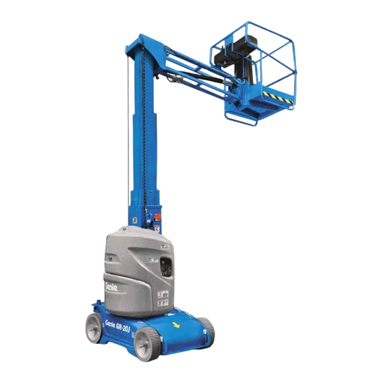
- Page 1 Service Manual Serial Number Range -20J ™ from GRJL-2298 -26J ™ Original Instructions Part No. 1312899GT Rev A March 2022...
-
Page 2: Read, Understand And Obey The Safety Rules And Operating Instructions In The Appropriate Operator's Manual On Your Machine
1312899GT Rev A, March 2022 Second Edition, First Printing Machine Classification Genie is a registered trademark of Terex South Dakota, Inc. in Group B/Type 3 as defined by ISO 16368 the U.S.A. and many other countries. “GR” is a trademark of Terex South Dakota, Inc. -
Page 3: Revision History
March 2022 Service Manual Introduction Revision Hist ory Revision History Revision Date Section Procedure / Page / Description 3/2022 Initial Release Reference Examples: Section – Maintenance, B-3 Electronic Version Section – Repair Procedure, 4-2 Click on any content or procedure in the Table of Contents to view Section –... -
Page 4: Serial Number Legend
Service Manual March 2022 Introduction Serial Number Legend 1 Model 2 Facility code 3 Sequence number 4 Serial label 5 Serial number (stamped on chassis) ™ -20J • GR ™ -26J Part No. 1312899GT... -
Page 5: Safety Rules
March 2022 Service Manual Safety Rules Gene ral Saf ety Rul es Secti on 1 Safety Rul es Danger Failure to obey the instructions and safety rules in this manual and the appropriate Operator's Manual on your machine will result in death or serious injury. - Page 6 Service Manual March 2022 Safety Rules Personal Safety Workplace Safety Any person working on or around a machine Any person working on or around a machine must be aware of all known safety hazards. must be aware of all known safety hazards. Personal safety and the continued safe Personal safety and the continued safe operation of the machine should be your top...
-
Page 7: Table Of Contents
March 2022 Table of Contents Introduction Introduction ...................... ii Important Information ..................ii Revision History ....................iii Serial Number Legend ..................iv Section 1 Safety Rules ...................... v General Safety Rules ..................v Section 2 Specifications ....................1 Machine Specifications ..................1 Performance Specifications ................ - Page 8 March 2022 Table of Contents Section 3 Scheduled Maintenance Procedures .............. 9 Introduction ......................9 Pre-Delivery Preparation Report ............... 12 Maintenance Inspection Report ................ 14 Checklist A Procedures ................. 15 A-1 Perform 30 Day Service ................15 A-2 Replace the Hydraulic Suction Strainer ............15 Checklist B Procedures .................
- Page 9 March 2022 Table of Contents Section 4 Repair Procedures ..................33 Introduction ...................... 33 Platform Controls ................... 35 1-1 Circuit Boards ..................... 35 1-2 Controller Adjustments ................35 How to Activate or Deactivate the Motion Alarm ........... 36 How to Activate or Deactivate the Flashing Beacon (if equipped) ....37 How to Calibrate the Joystick ...............
- Page 10 March 2022 Table of Contents Function Manifold ..................64 7-1 Function Manifold Components ..............64 7-2 Valve Adjustments – Function Manifold ............66 Hydraulic Tank ....................68 8-1 Hydraulic Tank ................... 68 Turntable Components .................. 69 9-1 Turntable Rotation Hydraulic Motor ............69 9-2 Battery .......................
- Page 11 March 2022 Table of Contents Section 5 Fault Codes ..................... 81 Introduction ...................... 81 Fault Code Chart ....................83 Section 6 Schematics ..................... 95 Introduction ...................... 95 ECM Pin Legend ....................96 Limit Switch and Sensor Legend ............... 98 Electrical Symbols Legend................99 Hydraulic Symbols Legend ................
- Page 12 Service Manual March 2022 This page intentionally left blank. ™ -20J • GR ™ -26J Part No. 1312899GT...
-
Page 13: Specifications
March 2022 Service Manual Specifications Secti on 2 Specificatio ns Machine Specifications Machin e Specific atio ns Tires and wheels Tire size (solid rubber) 16 x 5 x 11 in Batteries, Standard 40,6 x 12,7 x 28 cm Voltage 2V DC Castle nut torque, dry 89 ft-lbs 120 Nm... -
Page 14: Performance Specifications
Service Manual March 2022 Specifications Perfor man ce Speci ficatio ns Performance Specifications Drive speed, maximum Platform stowed 2.8 mph 40 ft / 9.8 sec 4,5 km/h 12,2 m / 9,8 sec Platform raised 0.4 mph 40 ft / 54.8 sec 0.65 km/h 12.2 m / 54.8 sec Braking distance, maximum... -
Page 15: Hydraulic Component And Manifold Specifications
March 2022 Service Manual Specifications Hydraulic Com pon ent and Manif old Sp ecificati ons Hydraulic Component Manif old Co mpo nent Specifica tions Manifold Component Specifications Specifications Function Pump Plug torque Type Gear SAE No. 2 36 in-lbs / 4 Nm Displacement per revolution 0.256 cu in SAE No. -
Page 16: Hydraulic Oil Specifications
Service Manual March 2022 Specifications Hydraulic Oil Specific ations Hydraulic Oil Specifications Do not top off with incompatible hydraulic fluids. Hydraulic fluids may be incompatible due to the Hydraulic Fluid Specifications differences in base additive Genie specifications require hydraulic oils which are chemistry. -
Page 17: Hydraulic Hose And Fitting Torque Specifications
March 2022 Service Manual Specifications Hydraulic Hose and Fitti ng Tor que Sp ecificati ons Hydraulic Hose and Fitting SAE O-ring Boss Port Torque Specifications (tube fitting - installed into Aluminum) (all types) Your machine is equipped with Parker Seal-Lok™ SAE Dash Size Torque ORFS or 37°... -
Page 18: Torque Procedure
Service Manual March 2022 Specifications Tor que P roce dur e Torque Procedure JIC 37° fittings Align the tube flare (hex nut) against the nose Seal-Lok™ fittings of the fitting body (body hex fitting) and tighten the hex nut to the body hex fitting to Replace the O-ring. - Page 19 March 2022 Service Manual Specifications Working clockwise on the body hex fitting, make a second mark with a permanent ink marker to indicate the proper tightening position. Refer to Illustration 2. Note: Use the JIC 37° Fitting table in this section to determine the correct number of flats, for the proper tightening position.
-
Page 20: Sae And Metric Fasteners Torque Charts
Service Manual March 2022 Specifications SAE and Me tric Fast ene rs T orq ue Ch arts ™ -20J • GR ™ -26J Part No. 1312899GT... -
Page 21: Scheduled Maintenance Procedures
March 2022 Service Manual Scheduled Maintenance Procedures Secti on 3 Schedule d M ainte nanc e Proc edu res Intro ductio n Machine Configuration: Unless otherwise specified, perform each procedure with the machine in the following configuration: • Machine parked on a firm, level surface Observe and Obey: •... - Page 22 Service Manual March 2022 Scheduled Maintenance Procedures About This Section Maintenance Symbols Legend Note: The following symbols have been used in This section contains detailed procedures for each this manual to help communicate the intent of the scheduled maintenance inspection. instructions.
- Page 23 March 2022 Service Manual Scheduled Maintenance Procedures Pre-delivery Preparation Report The pre-delivery preparation report contains checklists for each type of scheduled inspection. Make copies for each inspection. Store completed forms as required. Maintenance Schedule The Scheduled Maintenance Procedures section and the Maintenance Inspection Report have been divided into subsections.
-
Page 24: Pre-Delivery Preparation Report
Service Manual March 2022 Pre-Delivery Preparation Report Pre-Delive ry Pr epa ratio n Rep ort Fundamentals Instructions It is the responsibility of the owner or dealer to Use the operator’s manual on your machine. perform the Pre-delivery Preparation. The Pre-delivery Preparation consists of The Pre-delivery Preparation is performed prior to completing the Pre-operation Inspection, the each delivery. - Page 25 March 2022 Service Manual This page intentionally left blank. Part No. 1312899GT ™ -20J • GR ™ -26J...
-
Page 26: Maintenance Inspection Report
Service Manual March 2022 Maintenance Inspection Report Maint enan ce In specti on Re por t Model Checklist A Y N R Checklist C Y N R Serial number Calibrate platform Perform after 40 hours: overload Date 30-day service Breather cap - models Hour meter Perform after 100 hours: with optional oil... -
Page 27: Checklist A Procedures
March 2022 Service Manual Checklist A Procedures Chec klis t A Pr oce d ur es A-2 Repl ace t he Hyd raulic Suction Strain er A-1 Perf orm 30 D ay Ser vice Replace the Hydraulic Suction Perform 30-Day Service Strainer The 30-day maintenance procedure is a one time procedure to be performed after the first 30 days... - Page 28 Service Manual March 2022 Checklist A Procedures Tag, disconnect and plug the hydraulic hoses at the function manifold. Cap the fittings on the manifold. Bodily injury hazard. Spraying hydraulic oil can penetrate and burn skin. Loosen hydraulic connections very slowly to allow the oil pressure to dissipate gradually.
-
Page 29: Checklist B Procedures
March 2022 Service Manual Checklist B Procedures Chec klis t B Pr oce d ur es B-1 Ins pect t he Bat teri es Note: Fully charge the batteries and allow the batteries to rest 24 hours before performing this Inspect the Batteries procedure to allow the battery cells to equalize. - Page 30 Service Manual March 2022 Checklist B Procedures Check the ambient air temperature and adjust Check the ambient air temperature and adjust the specific gravity reading for each cell as the specific gravity reading for each cell as follows: follows: • Add 0.004 to the reading of each cell for •...
-
Page 31: Inspect The Electrical Wiring
March 2022 Service Manual Checklist B Procedures B-2 Ins pect t he Elect rical Wiri ng Turn the key switch to the off position and push in the red Emergency Stop button to the Inspect the Electrical Wiring off position at the ground controls. Tag and disconnect the cables from the ground terminal of the battery. -
Page 32: Inspect The Tires And Wheels
Service Manual March 2022 Checklist B Procedures B-3 Ins pect t he Tires an d Whe els 13 Lower the jib boom until the platform is approximately 2 feet / 0,5 m from the ground. Inspect the Tires, Wheels and 14 Turn the key switch to the off position and Castle Nut Torque push in the red Emergency Stop button to the... -
Page 33: Test The Drive Brakes
March 2022 Service Manual Checklist B Procedures B-4 T est th e Driv e Brak es Press the drive function select button. Test the Drive Brakes Genie requires that this procedure be performed every 250 hours or quarterly, whichever comes first. -
Page 34: Test The Drive Speed - Stowed Position
Service Manual March 2022 Checklist B Procedures B-5 T est th e Driv e Spee d – St owed P osition Press the drive function select button. Test the Drive Speed – Stowed Position Genie requires that this procedure be performed every 250 hours or quarterly, whichever comes first. -
Page 35: Test The Drive Speed - Raised Position
March 2022 Service Manual Checklist B Procedures B-6 T est th e Driv e Spee d – R aised Position Press the lift function select button. Test the Drive Speed - Raised Position Genie requires that this procedure be performed every 250 hours or quarterly, whichever comes first. -
Page 36: Test The Flashing Beacon (If Equipped)
Service Manual March 2022 Checklist B Procedures B-7 T est th e Fl ashin g Beac on (i f eq uippe d) B-8 T est th e M otion Alarm Test the Flashing Beacons Test the Motion Alarm (if equipped) Genie specifications require that this procedure be performed every 250 hours or quarterly, whichever Genie specifications require that this procedure be... -
Page 37: Visual Inspection Of The Hydraulic Oil
March 2022 Service Manual Checklist B Procedures B-9 Visual I nspec tion of th e Hyd raulic Oil Press and hold the function enable switch on the joystick. Move the joystick off center, hold Visual Inspection of the Hydraulic for a moment and then release it. Move the joystick off center in the opposite direction, hold for a moment and then release it. -
Page 38: Inspect The Breather Cap
Service Manual March 2022 Checklist B Procedures B-10 In spect the B reat her Cap B-10 Collect a sample of hydraulic oil and place in a clear container. Visually inspect the Inspect the Breather Cap hydraulic oil for the following: •... -
Page 39: Inspect The Rear Axle Free-Wheel
March 2022 Service Manual Checklist B Procedures B-11 In spect the Rea r Axle F re e-wh eel B-11 Move the brake release toggle switch to the right to release the brakes. Check the Free-wheel Configuration Result: The parking brakes release and the alarm will sound. -
Page 40: Inspect The Lateral Offset Of The Mast
Service Manual March 2022 Checklist B Procedures B-12 In spect the Lat eral Offse t of t he Mast B-12 Apply approximately 29.5 ft-lb / 40 Nm of side force near the floor of the platform at location Inspect the Lateral Offset of the "F". -
Page 41: Inspect The Mast Wear Pads
March 2022 Service Manual Checklist B Procedures B-13 In spect the Mas t Wea r Pads B-13 Using a suitable lifting device, place a 440 lbs / 200 Kg test weight in the center of the Inspect the Mast Wear Pads platform. -
Page 42: Checklist C Procedures
Service Manual March 2022 Checklist C Procedures Chec klis t C Pr oce d ur es C-1 Calib rat e the Platfo rm Overl oad Syst em Models equipped with the platform overload option are provided with additional machine components: Calibrate the Platform Overload an adjustable spring-loaded platform support System... -
Page 43: Repalce The Hydraulic Tank Breather Cap - Models With Optional Hydraulic Oil
March 2022 Service Manual Checklist C Procedures C-2 Re palce t he Hy dra ulic T ank Br eath er C ap – Mo dels wit h Opti onal H ydr aulic Oil Replace the Hydraulic Tank Breather Cap - Models with Optional Hydraulic Oil Genie specifications require that this procedure be performed every 500 hours or six months,... -
Page 44: Checklist E Procedures
Service Manual March 2022 Checklist E Procedures Chec klis t E Pr oce dur e s E-1 T est o r Repl ace t he Hy dra ulic Oil Place a suitable container under the hydraulic tank. Refer to Specifications, Machine Test or Replace the Hydraulic Oil Specifications. -
Page 45: Repair Procedures
March 2022 Service Manual Repair Procedures Machine Configuration: Secti on 4 Repair P roce dur es Intro ductio n Unless otherwise specified, perform each repair procedure with the machine in the following configuration: • Machine parked on a firm, level surface •... - Page 46 Service Manual March 2022 Repair Procedures About This Section Symbols Legend Safety alert symbol—used to alert Most of the procedures in this section should only personnel to potential personal be performed by trained service professional in a injury hazards. Obey all safety suitably equipped workshop.
-
Page 47: Platform Controls
March 2022 Service Manual Platform Controls Platf or m Con tr ols 1-1 Cir cuit Bo ards The platform controls are used to operate the machine from the platform. The platform controls Circuit Boards are used to operate the various machine functions. The platform controls consist of an electronic How to Remove the Platform circuit board, joystick, alarm, buttons and LEDs. -
Page 48: Controller Adjustments
Service Manual March 2022 Platform Controls 1-2 C ontr oller Adj ustm ents Briefly press and release the drive function button to turn the motion alarm on or off. Controller Adjustments Result: The drive indicator light will be on if How to Activa te o r De activat e th e M otion Ala rm How to Activate or Deactivate the the motion alarm is activated.It will be off if the... -
Page 49: How To Activate Or Deactivate The Flashing Beacon (If Equipped)
March 2022 Service Manual Platform Controls How to Activa te o r De activat e th e Fl ashing Beaco n (if eq uippe d) How to Activate or Deactivate the Briefly press and release the lift function button to turn the flashing beacon on or off. Flashing Beacon (if equipped) Result: The lift indicator light will be on if the The flashing beacon is installed to alert operators... -
Page 50: How To Calibrate The Joystick
Service Manual March 2022 Platform Controls How to Cali brat e th e Joys tick How to Calibrate a Joystick Move the joystick fully to the left, then return the joystick to the neutral position. Calibration of the joystick is essential for safe Note: Do not squeeze or activate the joystick machine operation. -
Page 51: How To Calibrate The Steer Angle Sensor
March 2022 Service Manual Platform Controls How to Cali brat e th e Stee r Angl e Sens or How to Calibrate the Steer Angle Simultaneously press and hold all three function buttons for 3 seconds. Sensor Result: A beep sounds and three function Calibration of the steer angle sensor is essential indicator lights will flash one after another. - Page 52 Service Manual March 2022 Platform Controls 12 Press the jib boom function button for 1 second to validate the right side steering limit. 13 Press and hold the joystick function enable switch and activate the thumb rocker switch placing the wheels in line with the chassis. 14 Press the lift function button for 1 second.
-
Page 53: Platform Components
March 2022 Service Manual Platform Components Platf or m Com po ne nt s 2-1 Plat for m Remove the fasteners securing the outlet mounting plate to the platform. Set the Platform mounting plate assembly and fasteners to the side. How to Remove the Platform Attach a lifting strap of suitable capacity from an overhead supporting device to the bottom... -
Page 54: Platform Overload System
Service Manual March 2022 Platform Components 2-2 Plat for m Ove rloa d Syste m Tighten the overload spring adjustment screw just until the screw and lock nut will rotate Platform Overload System freely, and the clearance between the lock nut and sensor mounting bracket is minimal. - Page 55 March 2022 Service Manual Platform Components Turn the adjusting screw of the number 11 Turn the key switch to ground controls. 1 overload sensor 10° in a counterclockwise 12 Test all machine functions from the ground direction. controls. Result: The overload indicator lights are Result: All ground control functions do not flashing at the ground and platform controls, operate.
-
Page 56: Jib Components
Service Manual March 2022 Jib Components Jib C om p one nt s 3-1 Ji b Cylind er Turn the key switch to the off position and push in the red Emergency Stop button to the Jib Cylinder off position at both the ground and platform controls. - Page 57 March 2022 Service Manual Jib Components Attach a lifting strap from an overhead lifting device to the lug on the rod-end of the jib cylinder. Place a block across both sides of the jib boom under the jib cylinder. Use a soft metal drift to remove the barrel-end pivot pin and rod-end pivot pin.
-
Page 58: Mast Components
Service Manual March 2022 Mast Components Mast Com p o nen ts 4-1 Mast Ass embly Turn the key switch to the off position and push in the red Emergency Stop button to the Mast Assembly off position at both the ground and platform controls. - Page 59 March 2022 Service Manual Mast Components Attach a lifting strap of suitable capacity from 13 Remove the fasteners securing the stops to an overhead lifting device to the mast head, the mast assembly and remove the stops. Set jib boom and platform assembly. Support the the fasteners and stops to the side.
- Page 60 Service Manual March 2022 Mast Components 15 Using an overhead lifting device, attach a lifting strap of suitable capacity equipped with the M16 shackles to the threaded rings at the top of the outer mast. 16 Lift the mast assembly approximately 12 inches / 30 cm.
- Page 61 March 2022 Service Manual Repair Procedures GR-26J 1 number 1 mast 2 shims 3 wear pads 4 fasteners 5 stops 6 number 2 mast 7 number 3 mast 8 number 4 mast 9 cover plate Part No. 1312899GT ™ -20J • GR ™...
-
Page 62: How To Disassemble The Mast, Gr-26J
Service Manual March 2022 Repair Procedures How to Disa ssem ble t he Mast, GR-2 6J How to Disassemble the Mast, GR-26J Bodily injury hazard. This procedure requires specific repair skills, lifting equipment and a suitable workshop. Attempting this procedure without these skills and tools could result in death or serious injury and significant component damage. - Page 63 March 2022 Service Manual Repair Procedures Slide the number 2 mast and the number 14 Working from the bottom of the number 3 mast towards the top of the number 1 mast 2 mast, pull the number 3 mast half way out. to gain the access to the stops at the bottom 15 Attach a lifting strap from an overhead of the number 1 mast.
- Page 64 Service Manual March 2022 Repair Procedures 18 Tag and remove the inner wear pads from the 21 Tag and remove the outer wear pads and top of the number 3 mast section. Set the shims from the bottom of the number 1 mast shims to the side.
-
Page 65: How To Assemble The Mast, Gr-26J
March 2022 Service Manual Repair Procedures How to Asse mble the Mas t, GR- 26J Install six 12 mm wear pads, and the corresponding shims removed in the mast How to Assemble the Mast, disassembly process, onto the bottom of mast GR-26J sections 1, 2, 3 and 4. - Page 66 Service Manual March 2022 Repair Procedures Apply grease onto the outer faces of the mast sections 1, 2, 3 and 4. Carefully assemble the mast sections using the mast disassembly procedure in reverse order. Refer to Repair Procedure, How to Disassemble the Mast, GR-26J.
- Page 67 March 2022 Service Manual Repair Procedures GR-20J 1 number 1 mast 2 stops 3 shims 4 wear pads 5 number 2 mast 6 cover plate Part No. 1312899GT ™ -20J • GR ™ -26J...
-
Page 68: How To Disassemble The Mast, Gr-20J
Service Manual March 2022 Repair Procedures How to Disa ssem ble t he Mast, GR-2 0J How to Disassemble the Mast, GR-20J Bodily injury hazard. This procedure requires specific repair skills, lifting equipment and a suitable workshop. Attempting this procedure without these skills and tools could result in death or serious injury and significant component damage. -
Page 69: How To Assemble The Mast, Gr-20J
March 2022 Service Manual Repair Procedures How to Asse mble the Mas t, GR- 20J How to Assemble the Mast, Tag and remove the outer wear pads and shims from the bottom of the number 2 mast GR-20J section. Set the shims to the side. Discard the wear pads. - Page 70 Service Manual March 2022 Repair Procedures Install six 12 mm wear pads, and the Apply grease onto the outer faces of the mast corresponding shims removed in the mast sections 1 and 2. disassembly process, onto the bottom mast sections 1 and 2. Install two 10 mm wear pads, and the corresponding shims removed in the mast disassembly process, onto the top of mast...
-
Page 71: Lift Cylinder
March 2022 Service Manual Repair Procedures 4-2 Li ft Cylind er Place blocks under the chassis for support. Lower the machine onto the blocks. Lift Cylinder Crushing hazard. The chassis will fall if not properly supported. How to Remove the Lift Cylinder Bodily injury hazard. - Page 72 Service Manual March 2022 Repair Procedures Tag and disconnect the proximity sensor. Lay 13 Raise the mast head, jib boom and platform the proximity sensor to the side. assembly and move the assembly approximately 20 inches / 50 cm towards the 10 Tag, disconnect and plug the hydraulic hose non-steer end of the machine.
-
Page 73: Ground Controls
March 2022 Service Manual Ground Controls Gr oun d C on tr ols 5-1 L evel Se nsor Securely install the level sensor pigtail into the machine wire harness. Level Sensor Remove the plastic cap from the end of the The tilt alarm sounds when the incline of the level sensor calibration wire. -
Page 74: Hydraulic Pump
Service Manual March 2022 Hydraulic Pump Hydr au lic Pum p How to Remove the Hydraulic 6-1 Hy dra ulic Pum p Pump Hydraulic Pump Note: When removing a hose assembly or fitting, The hydraulic pump is attached to the motor which the O-ring (if equipped) on the fitting and/or hose makes up the hydraulic power unit. - Page 75 March 2022 Service Manual Hydraulic Pump Tag, disconnect and plug the hydraulic hoses 10 Remove the fasteners securing the function at the function manifold. Cap the fittings on pump to the function manifold. Set the the manifold. fasteners to the side. 11 Carefully remove the function pump from the Bodily injury hazard.
-
Page 76: Function Manifold
Service Manual March 2022 Function Manifold Fu ncti o n M ani fol d 7-1 Func tion Manif old C omp one nts Function Manifold Components The function manifold is mounted on the hydraulic pump. Index No. Description Schematic Item Function Torque Filter... - Page 77 March 2022 Service Manual Function Manifold Part No. 1312899GT ™ -20J • GR ™ -26J...
-
Page 78: Valve Adjustments - Function Manifold
Service Manual March 2022 Repair Procedures 7-2 Valv e Adjust men ts – Fun ction Ma nifold From the ground controls, fully elevate the jib boom. Continue holding jib up while observing Valve Adjustments - Function the pressure reading on the pressure gauge. Manifold Note the pressure. - Page 79 March 2022 Service Manual Repair Procedures How to Adjust the Lift Relief Turn the key switch to the off position. Valve Hold the valve stem with a hex key and loosen the jam nut. Note: Verify the hydraulic oil level is at the FULL mark on the hydraulic tank.
-
Page 80: Hydraulic Tank
Service Manual March 2022 Hydraulic Tank Locate and remove the hydraulic tank filler Hydr au lic Ta nk 8-1 Hy dra ulic T ank cap. Set the filler cap to the side. Hydraulic Tank Remove the drain plug and drain all of the oil into a suitable container. -
Page 81: Turntable Components
March 2022 Service Manual Turntable Components Tur n ta ble C om po ne nt s 9-1 Tur nta ble Rot ation Hydr aulic Moto r Remove the rear chassis cover at the non- steer end of the machine and set aside. Turntable Rotation Hydraulic Remove the side cover of the drive chassis Motor... -
Page 82: Battery
Service Manual March 2022 Turntable Components 9-2 Bat tery Locate the bolts between the battery box and the counterweight. Loosen the bolts holding Battery the battery pack in position. How to Remove the Battery Electrocution/burn hazard. Contact with electrically charged circuits could result in death or serious injury. -
Page 83: Steer Axle Components
March 2022 Service Manual Steer Axle Components Steer Axle Com p on en ts 10-2 St eer Cylinde r 10-2 10-1 10-1 Y oke Steer Cylinder Yoke Assembly How to Remove the Steer How to Remove the Yoke Cylinder Assembly Note: When removing a hose assembly or fitting, Note: Perform this procedure on a firm, level the O-ring (if equipped) on the fitting and/or hose... - Page 84 Service Manual March 2022 Steer Axle Components 10-3 St eeri ng Ro d 10-3 Center a lifting jack under the drive chassis at the steer end of the machine. Steer Rod Raise the machine approximately 6 inches / 15 cm. Place blocks under the chassis for How to Remove the Steer Rod support.
-
Page 85: Steer Angle Sensor
March 2022 Service Manual Steer Axle Components 10-4 St eer Angle S enso r 10-4 Mount the potentiometer onto the plate and securely tighten with the nut. Steer Angle Sensor How to Replace the Steer Angle Sensor Adjust the steer tires so they are in a straight driving position. - Page 86 Service Manual March 2022 Steer Axle Components 11 Install the bottom plate and it's fasteners on the steer yoke pivot. 12 Install the sensor activator pin onto the steer yoke pivot. Note: Be sure the sensor activator pin is engaged into the sensor.
-
Page 87: Non-Steer Axle Components
March 2022 Service Manual Non-Steer Axle Components Non-S teer Ax le C om po ne nts 11-1 11-1 Drive Mot ors Open the turntable cover at the ground control side of the machine. Drive Motors How to Remove a Drive Motor Block the steer wheels. - Page 88 Service Manual March 2022 Non-Steer Axle Components 10 Turn over the steel bar and cut the zip ties 17 Place a 2 x 4 x 6 inch / 5 x 10 x 15 cm long attaching the two wire harness connectors to wood block under the left drive motor.
-
Page 89: Drive Brake
March 2022 Service Manual Non-Steer Axle Components 11-2 Drive B rake 11-2 Drive Brake How to Remove the Drive Brake Remove the drive motor assembly. Refer to Repair Procedure, How the Remove a Drive Motor. 1 drive brake 2 drive motor 3 speed reducer 4 mounting plate 5 fasteners... -
Page 90: Battery Charger
Service Manual March 2022 Battery Charger Batter y Char ger 12-1 12-1 B atte ry Cha rg er Tag and disconnect the charger cutout harness connector Battery Charger How to Remove the Battery Charger Electrocution/burn hazard. Contact with electrically charged circuits could result in death or serious injury. -
Page 91: Battery Charger Staus Indicator
March 2022 Service Manual Battery Charger Battery C har ger Staus Indica tor Battery Charger Status Indicator Battery C har ger not Ope ratin g Battery Charger not Operating If the battery charger fails to operate when plugged into an AC power source, check the following: •... -
Page 92: How To Reset The Battery Charger
Service Manual March 2022 Battery Charger How to Re set t he Bat tery C har ge r How to Reset the Battery Charger Turn the key switch to the off position and push in the red Emergency Stop button to the off position at both the ground and platform controls. -
Page 93: Fault Codes
March 2022 Service Manual Fault Codes Secti on 5 Fault C odes Before Troubleshooting: Intro ductio n Read, understand and obey the safety rules and operating instructions in the appropriate operator's manual on your machine. Be sure that all necessary tools and test ... -
Page 94: About This Section
Service Manual March 2022 Fault Codes About This Section LED Diagnostic Readout When a malfunction is discovered, the fault code The diagnostic readout displays numerical codes charts in this section will help a service that provide the information about the machine professional pinpoint the cause of the problem. -
Page 95: Fault Code Chart
March 2022 Service Manual Fault Codes Fault C ode Cha rt Fault Code Chart Error Source Error Type Condition Solution Name Name The base board is waiting This alarm may appear from time Controller Logic fault #1 for the controller to complete to time upon starting. - Page 96 Service Manual March 2022 Fault Codes Error Source Error Type Condition Solution Name Name Controller Serial error #1 The controller has not Replace the controller. interface responded to the request board from the base board as expected. Logic failure #1 Under-voltage or If the fault occurs on starting or over- voltage has been...
- Page 97 March 2022 Service Manual Fault Codes Error Source Error Type Condition Solution Name Name Controller Multi selection The electric brake is short- Check the conformity of the control interface circuited. selectors. board Several movements activated simultaneously. Plat. double The controller receives Check the wiring or change the required several commands...
- Page 98 Service Manual March 2022 Fault Codes Error Source Error Type Condition Solution Name Name Controller Joystick Joystick is pushed when Repair or replace the joystick. interface machine is switching on. board Short-circuit on The function switch has It should be possible to stop the function been closed for more than alarm by stopping the main...
- Page 99 March 2022 Service Manual Fault Codes Error Source Error Type Condition Solution Name Name Controller Descent valve There is a problem on one Check the condition of the valves interface or other of the following and their connections. Otherwise, it board outputs: terminal A30, is an internal fault of the controller.
- Page 100 Service Manual March 2022 Fault Codes Error Source Error Type Condition Solution Name Name Controller Type disparity The controller and the base It is an internal fault. Replace the logic board board are not suitable for controller. the type of operation chosen by the operator.
- Page 101 March 2022 Service Manual Fault Codes Error Source Error Type Condition Solution Name Name Controller Stand by pump The current sensor of the It is an internal fault. Replace the logic board pump detects a current controller. other than zero when the pump is not working.
- Page 102 Service Manual March 2022 Fault Codes Error Source Error Type Condition Solution Name Name Controller VMN high The VMN voltage of one of This alarm appears only on start- logic board the motors is high when it up. Check: internal motor should be low.
- Page 103 March 2022 Service Manual Fault Codes Error Source Error Type Condition Solution Name Name Controller VMN left low The VMN voltage of the left This alarm only appears when the logic board motor is low when it should drive motors are activated. Check: be high.
- Page 104 Service Manual March 2022 Fault Codes Error Source Error Type Condition Solution Name Name Controller Drive shorted The drive output of the base It is an internal fault. Replace the logic board board is short- circuited. controller. Driver 3 The base board and the It is an internal fault.
- Page 105 March 2022 Service Manual Fault Codes Error Source Error Type Condition Solution Name Name Controller Pump shorted The pump inputs of the base It is an internal fault. Replace the logic board board are short- circuited. controller. No CAN The interface board has not Check the BUSCAN connection message received the message from...
- Page 106 Service Manual March 2022 Fault Codes Error Source Error Type Condition Solution Name Name Platform System Internal system surveillance It is an internal fault. Replace the controls surveillance has been put into operation. controller. circuit board If the surveillance detects a fault in the execution of this surveillance, this alarm appears.
-
Page 107: Schematics
March 2022 Service Manual Schematics About This Section Secti on 6 Schematic s Intro ductio n There are two groups of schematics in this section. Electrical Schematics Electrocution/burn hazard. Contact with electrically charged Observe and Obey: circuits could result in death or serious injury. -
Page 108: Ecm Pin Legend
Service Manual March 2022 Schematics ECM Pin Le gend ECM Pin Legend 1 ground controls ECM Pin Legend Pin number Description Not activated Activated +24V Ground control selection supply +24V DC Power supply Tilt signal +12V Power supply Steer signal mid-point 2.5V CAN·L signal CAN-H signal... - Page 109 March 2022 Service Manual Schematics ECM Pin Legend, cont. Pin number Description Not activated Activated Mast up / turntable rotate signal Mast up / down signal Jib signal Turntable rotate signal +24V Solenoid valve / F2 fuse power 0V Tilt indicator LED 0V Turntable rotate valve 0V Mast base valve 0V Steer valve...
-
Page 110: Limit Switch And Sensor Legend
Service Manual March 2022 Limit Switch and Sensor Legend Limit Switch and S enso r Le gen d Limit and Sensor Legend 1 Platform overload LS31 2 Mast down LS18 3 Steer angle S21 4 Tilt sensor S7 5 Jib down LS11 ™... -
Page 111: Electrical Symbols Legend
March 2022 Service Manual Electrical Symbols Legend Electrical Sym bols Lege nd Circuits Crossing Switch or Button Motor Level Sensor (no connection) Diode Toggle Switch Battery Charger Solenoid Valve Connection Emergency Stop Button Battery Parking Brake (no terminal) Connector Key Switch Control Relay Electric Motor Fuse... -
Page 112: Hydraulic Symbols Legend
Service Manual March 2022 Hydraulic Symbols Legend Hydraulic Symbols Le gen d Hand pump Variable speed motor Pump, fixed displacement Check valve Cylinder, double acting Filter Relief valve with pressure Motor, bi-directional setting Solenoid operated Solenoid operated Solenoid operated Solenoid operated 2 position 2 way directional 2 position 2 way directional 2 position 2 way directional... -
Page 113: Electrical Schematics
March 2022 Service Manual Electr ica l Sch em ati cs Electrical Schematic, GRJ (from GRJL-2298) -
Page 114: Electrical Schematic, Grj (From Grjl-2298)
Service Manual March 2022 Electrical Sch emati c, GRJ (fr om GR JL- 2298 ) Electrical Schematic, GRJ (from GRJL-2298) GROUND CONTROL:01 TS100 TO EP207 +BAT POWER SUPPLY:02 TILT TO GROUND TILT:03 TO4:INTERFACES IS 102 TURNTABLE ANGLE TO EP209 +12VDC:06 SHIELDED AND TWISTED CAN CABLE CAN H R4700... - Page 115 March 2022 Service Manual Electrical Schematic, GRJ (from GRJL-2298) PLATFORM PANEL CARD 324 324 324 324 SHIELDED AND TWISTED CAN CABLE PLATFORM LED PANEL X305 X305 X3J1 X3J3 SENSOR HARNESS EP319 AC201 PLATFORM GROUND AC201 PLATFORM CONTROL PANEL HARNESS WORKLIGHT X303 X303 X303...
- Page 116 Service Manual March 2022 Electrical Schematic, GRJ (from GRJL-2298)
- Page 117 March 2022 Service Manual GCON LED Panel, GRJ (from GRJL-2298)
-
Page 118: Gcon Led Panel, Grj (From Grjl-2298)
Service Manual March 2022 GCON LED Pan el, GRJ (fr om G RJL- 229 8) GCON LED Panel, GRJ (from GRJL-2298) TILT OVERLOAD GROUND/PLATFORM KEY SWITCH ES0630 A ™ -20J • GR ™ -26J Part No. 1312899GT... -
Page 119: Temperature Sensor Harness, Grj (From Grjl-2298)
March 2022 Service Manual Tem per atu re Sens or H arn ess, GR J (f rom GRJL -22 98) Temperature Sensor Harness, GRJ (from GRJL-2298) STEERING COIL +Vcc TS100 JIB LOWERING COIL AC104 TURNTABLE ROTATION COIL LIFT COIL AC111 X103 TEMPERATURE AC105... - Page 120 Service Manual March 2022 Temperature Sensor Harness, GRJ (from GRJL-2298)
- Page 121 March 2022 Service Manual Options, GRJ (from GRJL-2298)
-
Page 122: Options, Grj (From Grjl-2298)
Service Manual March 2022 Options , GRJ (fro m GRJ L-2 298 ) Options, GRJ (from GRJL-2298) TrackUnit shunt RESET PUSHBUTTON TrackUnit module pink purple pink gray 1:Joystick info(in) 2:+APC 3:+BAT 4:-BAT HQ SMS module A01:+APC UPC03 5:CAN-H A02:+VBAT 8:CAN-L A03:+VBAT A04:Flashing light A05:To HM relay(85) -
Page 123: Hydraulic Schematics
March 2022 Service Manual Hydr au lic Sc hem a tics Hydraulic Schematic, 2.2 kw (from GRJL-2298) -
Page 124: Hydraulic Schematic, 2.2 Kw (From Grjl-2298)
Service Manual March 2022 Hydraulic Schem atic, 2.2 kw (fr om GRJL- 229 8) Hydraulic Schematic, 2.2 kw (from GRJL-2298) JIB UP / DOWN TURNTABLE ROTATE 0.66 gpm 2,5 L/min EV11 EV12 MAST UP / DOWN REEL EV10 STEER 1450 PSI 1450 PSI 100 bar 100 bar... -
Page 125: Hydraulic Schematic, 3 Kw (From Grjl-2298)
March 2022 Service Manual Hydraulic Schem atic, 3 kw ( fro m GRJ L-2 298 ) Hydraulic Schematic, 3 kw (from GRJL-2298) JIB UP / DOWN TURNTABLE ROTATE 0.66 gpm 2,5 L/min EV11 EV12 MAST UP / DOWN REEL EV10 STEER 1450 psi 1450 psi... - Page 126 Service Manual March 2022 Hydraulic Schematic, 3 kw (from GRJL-2298) GR™-20 J • GR™-2 6J Part No. 131 289 9GT Service Manu al Marc h 20 22...
Need help?
Do you have a question about the Genie GR-20J and is the answer not in the manual?
Questions and answers