
Related Manuals for Universal Analyzers 1095E


Summary of Contents for Universal Analyzers 1095E
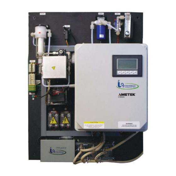
- Page 1 Instruction Manual Model 1095E Acid Aerosol "Freezer Chiller" 5200 Convair Drive Carson City, NV 89706 • Phone: 775-883-2500 • Fax: 775-883-6388 • www.universalanalyzers.com MAN.1095E. REVB.12232014...
-
Page 2: Table Of Contents
Contents Receiving and Storage Definition of Symbols Specifications Description and Principle of Operation Installation Electrical Connections Start-Up Shutdown Maintenance Troubleshooting Spare Parts Drawings - Model 1095E Limited Warranty Page 2 of 25 MAN.1095E.REVB.12232014... -
Page 3: Receiving And Storage
Receiving and Storage The Universal Analyzers Model 1095E Acid Aerosol "Freezer Chiller" is a complete assembly. No assembly is necessary when received on-site. Carefully inspect the product and any special accessories included with it immediately upon arrival by removing them from the packing and checking for missing components against the packing list. -
Page 4: Definition Of Symbols
SHOULD BE TAKEN BEFORE DISCONNECTING OR CONTACTING ANY ELECTRICAL CONNECTIONS. PROTECTIVE CONDUCTOR TERMINAL SYMBOL INDICATES THE TERMINAL LOCATION FOR THE PROTECTIVE CONDUCTOR. FAILURE TO CONNECT TO THE PROTECTIVE CONDUCTOR TERMINAL MAY RESULT IN A SHOCK HAZARD. Page 4 of 25 MAN.1095E.REVB.12232014... -
Page 5: Specifications
27" H x 21" W x 14 1/4" D Weight 75 lbs (34kg) Soluble Gas Removal Rates 0% loss <10% loss < 2% loss 0% loss < 2% loss *AT REDUCED FLOW RATE ABOVE 77°F. (25°C.) AMBIENT. Page 5 of 25 MAN.1095E.REVB.12232014... -
Page 6: Description And Principle Of Operation
The use of a heated filter and a heated sample line are required to be installed between the sample extraction location and the input of the 1095E sample cooler. The temperature of the sample must be kept above the boiling point of water and above the dew point of any chemical reactions that would skew the desired analytical results. - Page 7 The Model 1095E SO is manually controlled through the Operator Interface located on the front of the unit, or remotely by the I/O inputs to the PLC. The Interface is used to display and manually operate the 1095E Chiller. MAIN DISPLAY...
- Page 8 MAIN DISPLAY The Model 1095E "Freezer Chiller" is manually controlled through the Operator Interface located on the front of the unit, or remotely by the I/O inputs to the PLC. The 128x64 pixel operator interface (HMI) is used to display and manually operate the 1095E Chiller.
- Page 9 The Advance Sequence button is used to advance the Freezer Channel cycle for troubleshooting. The Turn System Online/Offline button is used to turn the Sample Pump on or off. The Main button returns to the Main Display screen. The Menu button returns to the Main Menu screen. Page 9 of 25 MAN.1095E.REVB.12232014...
-
Page 10: Installation
Customer 24VDC input signals to manually hold a column indefinitely are on TB5-1 and TB5-2. Customer 234VDC input signals to manually activate the system offline function are on TB5-3 and TB5-4. A 24VDC output signal to signify there is a system error may be wired on TB5-5 and TB5-6. Page 10 of 25 MAN.1095E.REVB.12232014... -
Page 11: Electrical Connections
Electrical Connections Model 1095E Page 11 of 25 MAN.1095E.REVB.12232014... -
Page 12: Start-Up
3. Allow the system to run for at least 10 minutes. 4. Once purging is complete disconnect and cap the sample outlet tube connections and disconnect power from the unit. Note: If electrical wires are to be disconnected, follow applicable ‘Lock Out/Tag Out’ requirements. Page 12 of 25 MAN.1095E.REVB.12232014... -
Page 13: Maintenance
4. Reinstall the drain fitting. Ensure pipe tape is used on the pipe threads before installation. Use a backup wrench on the heat exchanger lower hex to prevent damage to the exchanger. 5. Reconnected the drain, inlet and outlet tubes. Page 13 of 25 MAN.1095E.REVB.12232014... - Page 14 REPLACING PELTIER ELEMENT Contact Factory for Peltier replacement options. It is recommended on the 1095E Freezer Chiller elements be replaced at the factory. In rare occurrences a procedure to replace the elements may be obtained. Page 14 of 25...
-
Page 15: Troubleshooting
Replace heat sink fins Heat sink fins obstructed Clean heat sink fins Peltier elements failure Verify wire connections Replace elements Replace heat sink assembly Column frozen Online column frozen Reduce dwell time Check peristaltic tubing Page 15 of 25 MAN.1095E.REVB.12232014... - Page 16 (This assumes the heat exchanger is under a slight vacuum.) 4. The temperature of the air passing through the cooler to cool the heat sink is too high. This could be due to placement of the cooler in a tightly sealed box. Page 16 of 25 MAN.1095E.REVB.12232014...
-
Page 17: Spare Parts
PLC, Operator Interface DV-1000 5600-0006 PLC EA1-S3Ml C-More Micro Touch Screen 5600-0218 PLC, Shielded Interconnect Cable, DV-1000 5600-0022 100A Moisture Sensor Module 3600-0008 Freezer Heatsink Assembly 5209-0364 Electronics Enclosure Assembly 115VAC 5209-0366 Electronics Enclosure Assembly 230VAC 5209-0393 Page 17 of 25 MAN.1095E.REVB.12232014... - Page 18 Vacuum Switch, 0-29” Hg, Sample Inlet Vacuum 3103-0017 Solenoid Valve - Beco 115VAC 3-Way - Teflon 4955-0048 Solenoid Valve - Beco 230VAC 3-Way - Teflon 4955-0057 Flow Meter, 0-5 l/m, SS Needle Valve 4965-0008 Flow Meter Knob 4902-0002 Page 18 of 25 MAN.1095E.REVB.12232014...
-
Page 19: Drawings - Model 1095E
Drawings Model 1095E Page 19 of 25 MAN.1095E.REVB.12232014... - Page 20 Drawings Model 1095E Page 20 of 25 MAN.1095E.REVB.12232014...
- Page 21 Drawings Model 1095E Page 21 of 25 MAN.1095E.REVB.12232014...
- Page 22 Drawings Model 1095E Page 22 of 25 MAN.1095E.REVB.12232014...
-
Page 23: Limited Warranty
I. Limited Warranty 1. Limited Warranty. Universal Analyzers, Inc (UAI) offers a limited warranty on each of its products against failure due to defects in material and workmanship for a period ending the earlier of (i) fifteen (15) months from the date of the invoice relating to the sale of the product and (ii) twelve (12) months from the date of installation of the product (collectively, the “Initial Warranty”). - Page 24 Buyer must have: (i) paid all invoices to UAI in full, whether or not they are specifically related to the product at issue; and (ii) notified UAI of the limited warranty claim within sixty (60) days from the date Buyer knew or had reason to know of the defect Page 24 of 25 MAN.1095E.REVB.12232014...
- Page 25 5200 Convair Drive Carson City, NV 89706 • Phone: 775-883-2500 • Fax: 775-883-6388 • www.universalanalyzers.com Page 25 of 25 MAN.1095E.REVB.12232014...
Need help?
Do you have a question about the 1095E and is the answer not in the manual?
Questions and answers