
Related Manuals for Universal Analyzers SCP


Summary of Contents for Universal Analyzers SCP
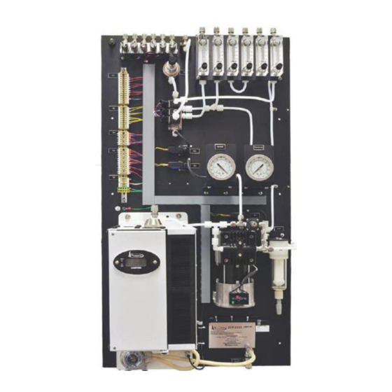
- Page 1 Instruction Manual Models SCP and SCU Sample Conditioning Plate 5200 Convair Drive Carson City, NV 89706 • Phone: 775-883-2500 • Fax: 775-883-6388 • www.universalanalyzers.com MAN.SCPSCU.REVD.03022015...
-
Page 2: Table Of Contents
Contents Receiving and Storage Definition of Symbols Specifications Description and Principle of Operation Installation Electrical Connections Process and Piping Connections Start-Up Shutdown Maintenance Troubleshooting Spare Parts Drawings Limited Warranty Page 2 of 43 MAN.SCPSCU.REVD.03022015... -
Page 3: Receiving And Storage
Receiving and Storage The Universal Analyzers Models SCP and SCU Sample Conditioning Systems are complete assemblies. No assembly is necessary when received on-site. Carefully inspect the product and any special accessories included with it immediately on arrival by removing them from the packing and checking for missing components against the packing list. -
Page 4: Definition Of Symbols
WARNING - EXPLOSION HAZARD - DO NOT DISCONNECT EQUIPMENT UNLESS POWER HAS BEEN SWITCHED OFF OR THE AREA IS KNOWN TO BE NON-HAZARDOUS. WARNING - EXPLOSION HAZARD - SAMPLE CONDITIONING SYSTEMS SCP OR SCU ARE NOT SUITABLE FOR HAZARDOUS AREA INSTALLATION. -
Page 5: Specifications
(External fuse required or 20A or less) Electrical Classification General Purpose Temperature Classification FM/CSA T3A, ATEX 143°C (T3) SCP Dimensions 38 1/2" H x 20 3/4" W SCU Dimensions 31" H x 19" W x 12" D Weight 75 lbs (34kg) -
Page 6: Description And Principle Of Operation
DESCRIPTION The key to the success of the Universal Analyzers Sample Cooler is being able to condense the water from a wet gas sample with a minimal loss of the water soluble gas fraction is due to the design of the heat exchanger. Please refer to Drawings P0147 and P0149. - Page 7 The result is a heat removal system with superior performance under all conditions. Universal Analyzers Thermoelectric Sample Coolers have a digital display as a front panel indication of the operating temperature (in degrees C) of the heat exchangers. In addition, there are two LED lamps to indicate the status of the cooler.
-
Page 8: Installation
Installation THE SUPPLY POWER CIRCUIT MUST INCLUDE AN OVERPROTECTION DEVICE WITH A MAXIMUM RATING OF 20 A. A DISCONNECT SWITCH MUST BE LOCATED IN CLOSE PROXIMITY TO THE COOLER. IF THE EQUIPMENT IS USED IN A MANNER NOT SPECIFIED BY THE MANUFACTURER, THE PROTECTION PROVIDED BY THE EQUIPMENT MAY BE IMPAIRED PER CLAUSE 5.4.4(I) IN STANDARD EN 61010-1. -
Page 9: Electrical Connections
Electrical Connections 3000 Series, Models SCP and SCU Page 9 of 43 MAN.SCPSCU.REVD.03022015... - Page 10 Electrical Connections 600 Series, Models SCP and SCU 240V 3 - 32 VDC Page 10 of 43 MAN.SCPSCU.REVD.03022015...
-
Page 11: Process And Piping Connections
Process Piping and Connections 3000 Series, Models SCP and SCU Page 11 of 43 MAN.SCPSCU.REVD.03022015... - Page 12 Process Piping and Connections 600 Series, Models SCP and SCU Page 12 of 43 MAN.SCPSCU.REVD.03022015...
-
Page 13: Start-Up
Start-Up NOTE: IT IS IMPORTANT THAT THE HEATED PROBE AND HEATED SAMPLE LINE SHOULD BE AT OPERATING TEMPERATURE BEFORE STARTING THE CHILLER AND SAMPLE PUMP. Apply power to the sample conditioning plate or U-bracket. The indicated temperature will start to drop immediately. It should be below the over-temperature alarm point in approximately four minutes and the “COOL”... -
Page 14: Maintenance
Maintenance Before performing any maintenance on the cooler, ensure that all plant safety procedures are followed. As with any electrical device, ensure power is removed before performing any procedures. The cooler is designed for maintenance free operation but if any is required, ensure power has been removed before maintenance or repair is performed. - Page 15 Maintenance MAINTENANCE SCHEDULE The cooler heat sink is used to dissipate heat away from the heat transfer block/ Peltier elements. Over time in an industrial environment, dust/ debris can build up between the fins on the back side of the heat sink. This build will reduce the efficiency of the cooler and can cause premature failure of the Peltier elements.
-
Page 16: Troubleshooting
Troubleshooting The following table should give an overview of possible errors and an instruction to check and to repair them (is not valid for the starting-up period of cooler). Error Possible reason Check/Repair No sample gas flow Heat exchanger plugged Check for an obstruction Remove heat exchanger from unit and disassemble... -
Page 17: Spare Parts
Spare Parts 3000 Series Consumable Parts Part Peristaltic Pump Tubing, #15, 5' length 9216-0002 6 Amp Slow Blow Fuse for 3000 Series Power Supply 3010-0005 12 Amp Fast Acting Fuse for 3000 Series Power Supply 3010-0006 Basic Parts Part Heat Exchanger/Impinger - 316SS 10" 5200-S010 Heat Exchanger/Impinger - Glass/Kynar 10"... - Page 18 Spare Parts 600 Series Consumable Parts Part Filter Element - 2 mm Ceramic 4980-0007 ADI Mini Dia-VAC Sample Pump Rebuild Kit 9515-0018 Peristaltic Pump Tubing, #15, 5' length 9216-0002 Heat Sink Paste, 0.1 ounce Container 8010-0001 Ceramic Filter Element, 2 µm 4980-0007 Basic Parts Part...
-
Page 19: Drawings
Drawings 600 Series, Model SCP Page 19 of 43 MAN.SCPSCU.REVD.03022015... - Page 20 Drawings 600 Series, Model SCP Page 20 of 43 MAN.SCPSCU.REVD.03022015...
- Page 21 Drawings 600 Series, Model SCP Page 21 of 43 MAN.SCPSCU.REVD.03022015...
- Page 22 Drawings 600 Series, Model SCP Page 22 of 43 MAN.SCPSCU.REVD.03022015...
- Page 23 Drawings 600 Series, Model SCU Page 23 of 43 MAN.SCPSCU.REVD.03022015...
- Page 24 Drawings 600 Series, Model SCU Page 24 of 43 MAN.SCPSCU.REVD.03022015...
- Page 25 Drawings 600 Series, Model SCU Page 25 of 43 MAN.SCPSCU.REVD.03022015...
- Page 26 Drawings 600 Series, Model SCU Page 26 of 43 MAN.SCPSCU.REVD.03022015...
- Page 27 Drawings 600 Series, Model SCU Page 27 of 43 MAN.SCPSCU.REVD.03022015...
- Page 28 Drawings 3000 Series, Model SCP Page 28 of 43 MAN.SCPSCU.REVD.03022015...
- Page 29 Drawings 3000 Series, Model SCP Page 29 of 43 MAN.SCPSCU.REVD.03022015...
- Page 30 Drawings 3000 Series, Model SCP Page 30 of 43 MAN.SCPSCU.REVD.03022015...
- Page 31 Drawings 3000 Series, Model SCP Page 31 of 43 MAN.SCPSCU.REVD.03022015...
- Page 32 Drawings 3000 Series, Model SCP 240V 3 - 32 VDC Page 32 of 43 MAN.SCPSCU.REVD.03022015...
- Page 33 Drawings 3000 Series, Model SCU Page 33 of 43 MAN.SCPSCU.REVD.03022015...
- Page 34 Drawings 3000 Series, Model SCU Page 34 of 43 MAN.SCPSCU.REVD.03022015...
- Page 35 Drawings 3000 Series, Model SCU Page 35 of 43 MAN.SCPSCU.REVD.03022015...
- Page 36 Drawings 3000 Series, Model SCU Page 36 of 43 MAN.SCPSCU.REVD.03022015...
- Page 37 Drawings 3000 Series, Model SCU Page 37 of 43 MAN.SCPSCU.REVD.03022015...
- Page 38 Drawings Models SCP and SCU Page 38 of 43 MAN.SCPSCU.REVD.03022015...
- Page 39 Drawings Models SCP and SCU Page 39 of 43 MAN.SCPSCU.REVD.03022015...
- Page 40 Drawings Models SCP and SCU Page 40 of 43 MAN.SCPSCU.REVD.03022015...
-
Page 41: Limited Warranty
I. Limited Warranty 1. Limited Warranty. Universal Analyzers, Inc (UAI) offers a limited warranty on each of its products against failure due to defects in material and workmanship for a period ending the earlier of (i) fifteen (15) months from the date of the invoice relating to the sale of the product and (ii) twelve (12) months from the date of installation of the product (collectively, the “Initial Warranty”). - Page 42 Limited Warranty 4. Expenses on Non-Warranty Work. All repairs or replacements by UAI after the expiration of any applicable limited warranty period will be performed in accordance with UAI’s standard rate for parts and labor. Further, if upon UAI’s inspection and review, UAI determines the condition of the products is not caused by a defect in UAI’s material and workmanship, but is the result of some other condition, including but not limited to damage caused by any of the events or conditions set forth in Section I.2., Buyer shall be liable for all direct expenses incurred by UAI to conduct the inspection and review of the product.
- Page 43 5200 Convair Drive Carson City, NV 89706 • Phone: 775-883-2500 • Fax: 775-883-6388 • www.universalanalyzers.com Page 43 of 43 MAN.SCPSCU.REVD.03022015...
Need help?
Do you have a question about the SCP and is the answer not in the manual?
Questions and answers