
Related Manuals for Glide CentroGlide


Summary of Contents for Glide CentroGlide
- Page 1 CentroGlide OWNER/USER MANUAL V 6.1 (2022) IMPORTANT For your safety and comfort please read carefully and understand all the features prior to using your new CentroGlide. (Previously known as Centro) Misuse may result in electrical or mechanical damage.
- Page 2 Puncture Repair P 33 Section 15. Technician Service ONLY P 35 Section 16. Wheelchair Occupant Vehicle Transport P 40 Note: This manual covers the basic PG controller operation in this manual. A more comprehensive PG Manual can be downloaded from www.glide.com.au...
- Page 3 Section 1. Introduction Thank you for choosing the CentroGlide Power Wheelchair. The CentroGlide model range is a Class B type wheelchair and is designed for Indoor/Outdoor use. This owners-manual covers all CentroGlide models. Model Versions CentroGlide TS, ER, XT and VL- Maximum User Weight 175 kg...
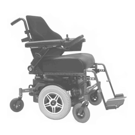
- Page 4 Section 2. Identifying Parts on your Wheelchair Fig 1 The illustration above lists common Parts on the CentroGlide Power Chair. 1. Attendant Joystick. (Optional) 12. Drive wheel clutch (optional) 2. Joystick 13. Attendant Brake 3. Seat Pan 14. Castor wheel (rear) 4.
- Page 5 Section 3. ⚠ Warnings Read and understand the warnings stated in this section. ⚠ Warning To the User Before using this chair, obtain advice and training from your Health Professional. Each chair is custom designed to suit individual needs. Take time to become familiar with each feature before you begin driving.
- Page 6 ⚠ Warning Environment Conditions The Glide Rehabilitation Products Power Chair has been designed and tested with user safety, as its prime consideration. The “Active Posi Trak” (APT) Suspension System has been designed to automatically adjust to uneven surfaces and changes in height, allowing all six wheels to stay in contact with the ground under most conditions.
- Page 7 • Never use your chair in a shower, swimming pool, sauna, ocean or lake. • If your environment has many steep obstacles, always have someone in attendance to assist you. • Avoid driving your wheelchair in sand or over rough surfaces. Apart from getting stuck you may also cause damage to wheels, bearings, gearboxes and motors.
- Page 8 Off and contact your carer or Glide Rehabilitation Products Agent. Although Glide has not had any reported instances of EMI, there has been anecdotal evidence over many years that EMI can have an impact on power chair controllers.
- Page 9 Check for any uncharacteristic noises, vibration or any difficulty in its use. If a problem is found, notify your carer and Glide Product Agent for repair or advice on how to repair. Do not drive it if your safety is at risk Make sure that the batteries are fully charged before operating.
- Page 10 Also used in More information relating to PG Controller can be viewed at www.glide.com.au Powered Wheelchairs – CentroGlide - Heading Related Documents - PG Manual. ⚠ Warning Never push the On/Off button on the Joystick module until you are seated correctly in the chair.
- Page 11 Do not displace the joystick when pressing the ON button. An error will occur and you will have to turn controller off and then back on again. Always set Speed selection to suit environment. Indoor driving should be set to a lower top speed.
- Page 12 Armrests The Flip up armrests are adjustable in height, position forward or aft of arm pad. These can be permanently set in the desired position and locked with bolts or user adjustable using locking knobs or thumb knobs. To adjust height, loosen Turn Knob located on outside of armrest Post. When adjustment is complete retighten Turn knob firmly.
- Page 13 Legrests and footrests The footrests are swing away and detachable. They swing out by pulling the release lever. When lever is released, the footplate will simply swing out and lift off the two locating Pins. When refitting footrest to wheelchair ensure that it is located on both locating pins. Damage may result if only one pin is used.
- Page 14 Drive Disengage/ Engage Your wheelchair may be fitted with one of two types of Drive disengagement for manually pushing the wheelchair. A. Motor Brake disengagement B. Clutch Drive Wheel disengagement. ⚠ WARNING. Before disengaging any Drive on your wheelchair please read the following. The wheelchair will have no braking when Drive is disengaged.
- Page 15 Type B – Drive Wheel Clutch Disengagement. The Drive Clutch is located in the centre of each driving wheel. It is identified as a large Black Knob with grip rings. To ENGAGE, simply turn Black Knob (Drive clutch) in either direction until you here a “click”.
- Page 16 Standard on all CentroGlide’s wheelchairs, unless otherwise ordered, is an incrementally adjustable Back Rest canes via Armrest/Back Canes bracket. It is advisable to have a Glide agent or trained Technician to make this adjustment. Electrically operated actuator. These are operated in several ways •...
- Page 17 CentroGlide has been designed to accommodate many of these systems including Glide’s own. Because of the varying nature of these systems and possible changes to the centre of gravity, it will be necessary for a Health Professional with the aid of...
- Page 18 Power Seat Tilt Your wheelchair will more than likely have a 50 degree power seat tilt which is a common recommendation by Health Professionals today. Whether you tilt your seat to the full extent is entirely your choice but you should be trained in its use and learn to feel safe with this features.
- Page 19 Section 6. Battery Maintenance and Charging Your Powerchair Battery Charger is specific to your wheelchair and may not be suitable for other Powerchairs. Only use the charger supplied with your wheelchair. The use of third party chargers may damage or shorten the life of your batteries. When should I Charge the Batteries You should charge after use each day.
- Page 20 Batteries Care and Storage Do not store near a heat source or in direct sunlight. Keep the terminals dry, clean and coat lightly with petroleum jelly to prevent corrosion. Batteries must be fully charged every 3 months if not in use. Battery installation and removal Battery installation should be carried out by qualified Technician.
- Page 21 If you believe your batteries are not properly secured or have come loose over time, cease driving your wheelchair and have it checked by a service technician. Consult your Glide Agent if battery replacement is required.
- Page 22 Battery Wiring Diagram Note: If warranted, packing blocks could be used to limit battery movement as batteries come in varying shapes and sizes.
- Page 23 Section 7. Care and Routine Maintenance The CentroGlide power wheelchair has been design for minimal service requirements and will give years of service if used correctly. Daily Charge your batteries every night so your Powerchair is ready to go when you are.
- Page 24 Vertical Lift wheelchairs do not require this stop. User Serviceable Parts The only user serviceable parts are as per Section 14 and 15. For safety, all other components are to be serviced by Glide Products or a trained Technician. Cleaning Wheelchair and parts Cleaning should be carried out regularly using a mild soapy solution for all painted surfaces and a damp cloth for all other areas.
- Page 25 Products agent or dealer. NOTE: As stated in our warranty, we recommend that your wheelchair be returned to a Glide Products agent for its free 3month safety check. This is a one off free service calculated from date of purchase.
- Page 26 This could happen going up a long steep hill or if been continually in a stalled situation. Give the wheelchair time to cool and try again. If the problem persists, then contact your Glide selling Agent.
- Page 27 Section 9. Precautions for Controller use The PG and Dynamic controllers have been designed with user safety as the prime consideration. They incorporate many, sophisticated self – test features which search for potential problems. If the controller detects a problem either in its own circuits, or in the wheelchairs electrical system, it may decide to halt the wheelchair depending on the severity of the fault.
- Page 28 Replacing Controller or Servicing Controllers ⚠ Warning Never swap Controller parts from another wheelchair. All replacement Power Modules will need re-programing by Qualified service Technician before use. If this is not done then Damage to motors may occur. The controller supplied with your wheelchair is specific to your wheelchair ONLY and has been programmed to suit wheelchair model and motor type attached to that wheelchair.
- Page 29 Section 10. Transfer In/ Out of your power chair. The Glide Rehabilitation Products Power Chair is designed in such a way that transferring in and out can be done with a minimum of fuss. Make sure that your chair is turned off before transferring.
- Page 30 The Vertical Lift and LAR versions is very similar in operation to the standard CentroGlide but has the added advantage of a 300mm vertical lift. This is ideal where users are in environments where constant change in seat heights are required such as the workplace or for home use.
- Page 31 Section 12. Warranty Glide Products Pty Ltd warrants the following as listed: The CentroGlide is warranted for a period of 12 months or as stated below. Controllers/Battery Charger 12-months warranty Controllers and associated hardware will be repaired where possible. Replacement will only occur if repair is not practical or not possible.
- Page 32 Part Number – 20120A 8” (200*50) Castor Wheel front pneumatic 8” Part Number – 20121A 8” (200*50) Castor Wheel front foam filled 8” Part Number – 20121A-F For more specific spare parts, view our web page www.glide.com.au under Spare Parts, CentroGlide. ...
- Page 33 Section 14 Puncture Repair. Replacing Inner Tube on Mid Drive Wheel Raise wheelchair 25mm to 50mm from the ground so the wheel can be removed. Using a 13mm socket spanner, remove Nyloc Nut and retainer washer from centre of wheel as per Fig 1 below and remove wheel from the wheelchair.
- Page 34 The wheel is now ready to be replaced back on the wheelchair. Before inserting on gearbox shaft, clean shaft with a cloth and slightly grease the shaft. Insert 5mm Key onto gearbox shaft and line hub keyway up with shaft key and slide wheel back on. Re- install the retainer washer and Nyloc Nut to shaft and tighten nut to 50 nm torque.
- Page 35 You must always re-assemble using a thread locking compound (Loctite 277 ®) or equivalent on the 5mm bolts. Failing to do so may result in bolts unscrewing. Never use substitute parts. Use only Glide spindle shaft, 5mm 8.8 bolts and special washer.
- Page 36 Replacing Inner Tube on Castor Wheel Remove wheel (make sure tyre is deflated) and then remove 4 nuts on wheel as per Fig 6. Once all 4 bolts have been removed you can remove one half of the hub which will leave the tyre and tube exposed Fig 7.
- Page 38 Section 15 Service Technician Only. Seat Frame stop ⚠ Warning The Seat Frame Stop is a safety stop only and is factory set to the correct height. If adjustment is required, then the following procedure must be followed. Firstly the Tilt seat actuator must be set in the bottomed (least tilt) position and then the adjuster set so it is just short of the seat frame by 1 to 2mm.
- Page 40 Wheelchair Occupant Transport Wheeled mobility devices for use as Seats in a Motor Vehicle. In accordance to AS3696.19 / ISO 7176-19 This section covers both 4-point tie-down system and the Dahl Docking station. Applicable to CentroGlide models excluding the Bariatric version.
- Page 41 Table of Contents 1. Safety Warning P 42 2. Overview P 43 3. Determining Motor Vehicle Size and type. P 44 4. Maximum User weight and Wheelchair Mass. P 44 5. Determining Motor Vehicle Size and type P 44 6. Wheelchair Securement in vehicle ( 4 strap tie-down) P 46 7.
- Page 42 2. The CentroGlide complies with ISO 7176-19 & AS/NZS 3696.19 and has been tested for use in a forward facing position ONLY. 3. The user must not weigh more than 159kg for CentroGlide secured with a 4 point WTORS and 136kg secured with a Dahl Docking station.
- Page 43 Overview. Crash Test The CentroGlide VL model was chosen as our test model, being the heaviest of all the CentroGlide models. The CentroGlide was dynamically tested in a forward facing test with ATD (test dummy) using both a 4 Point Wheelchair tie-down system and the Dahl Docking Station using a three-point-belt restraint comprising a pelvic-belt restraint and a shoulder-belt restraint that connect together near the hip of the occupant.
- Page 44 The size and type of wheelchair will impact on the type of vehicle suitable for Wheelchair Occupant transport. Smaller vehicles are generally not suitable for Occupant Transport of powered wheelchairs. The CentroGlide is a mid- wheel drive chair and has good manoeuvrability inside a vehicle. Vehicles with rear entry are the preferred vehicle type.
- Page 45 Wheelchair Securement The securement of the wheelchair must be in a forward-facing position in a motor vehicle. Fig 10. Fig 10. Four Point Strap –Type Tie-down system. The Tie-down system used must comply with ISO 10542-1. This will consist of two Front and two Rear attachment point and occupant restraint belts.
- Page 46 Securing the wheelchair with a 4 strap restraint system ⚠ Warning Standard ISO 10542-1 approved 4 point WTORS (wheelchair Tie down and Occupant Restraint Systems), are only tested to 85kg. For wheelchairs heavier than 85kg it is recommended to use an ISO 10542-1 WTORS (heavy duty system), which is rated for the total weight of the wheelchair including any options.
- Page 47 Wheelchair Tie-down location - 4 point Only use the designated Tie-down points on the wheelchair. (Fig. 11) ⚠ Warning Never be tempted to use any other point for attachment Fig 11 Each Tie-down attachment point on the wheelchair will be labelled with the Hook symbol as below.
- Page 48 Dahl VarioDock™. The lock plate and wheelchair adaptation kits are identical for both docking stations and both are suitable for securing the CentroGlide. The wheelchair must be secured in a forward facing direction. This wheelchair is tested to ISO 7176-19, for use in road vehicles and meets the requirements for forward facing transport and head on collisions.
- Page 49 Fitting of the Dahl lock plate on wheelchair In order to fit the Dahl Lock plate and additional wheelchair specific adaptation kit (Dahl part number #502237) is required to anchor the lock plate to the battery box. The lock plate and adaptation kit used is identical for both Dahl docking mk. ll and Dahl VarioDock™.
- Page 50 Dahl / CentroGlide adaption kit 502237...
- Page 51 Installation 1. Place nuts in predrilled battery box reinforcing plate holes and in the battery box with the recess down. 2. Underneath, fit the 8 mm spacer and additional 3mm spacer onto lock plate and put the five bolts (Dahl #502800) through the lock plate and spacers. 3.
- Page 52 Glide Adaption Kit Also, the CentroGlide if not fitted from standard must have the following kit installed. This kit comprises of pair of leg hanger mounts (L & R side) with 8mm socket screw added as per Fig12. This acts as an anti-detach for leg hangers. Also 6 x 8mm x 45mm...
- Page 53 Description of how the Dahl Docking system Mk ll. functions (1) Dahl Docking station (2) Lock plate and spacer (3) Lock pin (4) Red LED (5) Green LED (6) Control panel (7) Release button (8) Manual emergency release lever (9) manual operating lever...
- Page 54 Securing the wheelchair in the docking station 1. Maneuver the wheelchair slowly and in a uniform direction over the docking station. The lock plate under the wheelchair helps to guide the wheelchair into place in the docking station. When the lock plate is fully engaged in the docking station, a spring-action locking pin automatically secures the lock plate.
- Page 55 the docking station until the red LED on the control module, which indicates the unlock position, has been illuminated. ⚠ Warning Attempting to reverse the wheelchair before the red LED has been illuminated will result in blocking the docking stations locking mechanism, which makes it impossible to reverse.
- Page 56 1. Move wheelchair forward to remove the pressure on the lock pin 2. Place the emergency release tool in the gap between the locking plate and the docking station. 3. Push the release tool and wheelchair forward until the locking pin has been forced down - after which the wheelchair can reverse out of the docking station.
- Page 57 Wheelchair Set-up for Occupant transport ⚠ Warning 1. The Seat Tilt must be in the lowest down position. 2. The Back recline must be in the furthest upright position. 3. Head rest should be adjusted within 50mm of the back of the occupants head and the centre of the head restraint being at least as high as the rearward point on the back of the head during normal travel.
- Page 58 Occupant Restraints ⚠ Warning Only use a three-point-belt restraint which complies to ISO 10542-2, comprising a pelvic-belt restraint and a shoulder-belt restraint that connect together near the hip of the occupant. Belt restraints should make full contact with shoulder, chest and pelvis and the pelvic belts should be positioned low on the pelvis near the thigh-abdominal junction.
- Page 59 Illustration of proper belt-restraint fit. Fig 14. Illustration of improper belt-restraint fit.
- Page 60 Positioning the occupant restraint when using 4 strap ties-down ⚠ Warning The pelvic restraint belt must be worn low across the front of the pelvis so that the angle of the pelvic belt is within the optional or preferred zone of 30° to 75° to the horizontal. A steeper (greater) angle within the preferred zone, 45°...
- Page 61 Positioning the occupant restraint when using the Dahl Docking systems only ⚠ Warning When using wheelchair with Dahl Docking systems, the floor anchorage points for the occupant restraint system shall be located 10-60mm outside the wheels, on each side. The peliv belt must be worn low across the front of the pelvis so that the angle of the pelvic belt is within the optional or preferred zone of 30°...
- Page 62 Postural Support Devices During transportation, postural support devices where practical, should be removed where they may cause injury during an accident. Postural support devices should not be removed if the client’s safety is likely to be compromised during normal transport. It is recognized that in many cases postural support devices provide support during normal vehicle manoeuvres.
- Page 63 (but for this provision) would be conferred upon the purchaser or other persons against Glide Products Pty Ltd arising under or as a result of the Trade Practices Act 1974, any other legislation or the general law are excluded and limited...
Need help?
Do you have a question about the CentroGlide and is the answer not in the manual?
Questions and answers