Advertisement
Quick Links
Sec. 1
Service Information
Schematic Diagrams
Sec. 2
Circuit Board Diagrams
Sec. 3
Exploded Views &
Sec. 4
Replacement Parts Lists
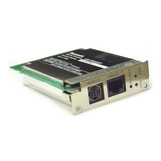
AW-PB309P/E
© 2002 Matsushita Electric Industrial Co., Ltd. All rights reserved.
Unauthorized copying and distribution is a violation of law.
ORDER NO. BSD0203M908
D12
WEB card
Advertisement

Related Manuals for Panasonic AW-PB309P/E


Summary of Contents for Panasonic AW-PB309P/E
- Page 1 ORDER NO. BSD0203M908 WEB card Sec. 1 Service Information AW-PB309P/E Schematic Diagrams Sec. 2 Circuit Board Diagrams Sec. 3 Exploded Views & Sec. 4 Replacement Parts Lists © 2002 Matsushita Electric Industrial Co., Ltd. All rights reserved. Unauthorized copying and distribution is a violation of law.
- Page 2 WARNING This service information is designed for experienced repair technicians only and is not designed for use by the general public. It does not contain warnings or cautions to advise non-technical individuals of potential dangers in attempting to service a product. Products powered by electricity should be serviced or repaired only by experienced professional technicans.
- Page 3 AW-PB309E - 2 -...
- Page 4 SAFETY PRECAUTIONS GENERAL GUIDELINES ELECTROSTATICALLY SENSITIVE (ES) DEVICES 1. When servicing, observe the original lead dress. If a short Some semiconductor (solid state) devices can be damaged circuit is found, replace all parts which have been over- easily by static electricity. Such components commonly are heated or damaged by the short circuit.
- Page 5 SERVICE INFORMATION CONTENTS 1. SOFTWARE VERSION UPGRADE................ INF-1 1-1. PLD Version Upgrade Procedure ..............INF-1 1-2. OS, Basic Software and Application Software Installation....... INF-4...
- Page 6 1. SOFTWARE VERSION UPGRADE 1-1. PLD Version Upgrade Procedure The AW-PB309 uses PLD. At the time of a version upgrade, use the special tool, connect the respective connection connectors, and use the PLD writing software. 1-1-1. PLD Chart Circuit board Number Connector PLD No.
- Page 7 C. Boot up the Ver. up Software and Ver. up Procedure Boot up the “MAX+plus II 9.6 programmer only” Software. On main window, select tab “MAX+plus II” and then “Programmer”. On main window (Programmer window is displayed), select tab “Option” and then “Hardware Setup”. On Hardware Setup dialog, set the “Hardware Type”...
- Page 8 Click the “Program” button on Programmer dialog. When Progress Bar reaches at point of 100, the message “Programming Complete” appears, then PLD version upgrade is completed. Click “OK” button on the Programming complete message Dialog. Progress bar * MAX+PLUS are registered tradmarks of Altera Corporation. * Windows95 and Windows98 are registered tradmarks of Microsoft Corporation.
- Page 9 1-2. OS, Basic Software and Application Software Installation The PLD of AW-PB309 is constructed with Hardware (no programmed IC), OS, Basic Software and Application Software. When replace IC, reprogram of the OS and Basic Software, and Application Software installation are needed.
- Page 10 • Type following parameter after “&” character. For PAL camx=pal& For NTSC camx=nt& • Press “Enter” key after input so that the setting is completed. 1-2-2. Application Software Installation Move / Copy the Application Software (vvpb309nt) to your PC HDD. This software has 4 files registered.
- Page 11 SCHEMATIC DIAGRAMS About indication of a circuit name Circuit Name COMPONENT Circuit Board No. F1:SERVO (CTL) NAME DRAWING NO. CIRCUIT BOARD NO. KR2D53 (1/17) VEP82230A-1 Drawing No. SCM001 Page No. NOTE: BE SURE TO MAKE YOUR ORDERS OF REPLACEMENT PARTS ACCORDING TO PARTS LIST CONTENTS MAIN (1/4) .......................SCM001 MAIN (2/4) .......................SCM002...
- Page 12 COMPONENT MAIN 01/04 NAME CIRCUIT BOARD NO. DRAWING NO. M2630FA SCM001...
- Page 13 COMPONENT MAIN 02/04 NAME CIRCUIT BOARD NO. DRAWING NO. M2630FA SCM002...
- Page 14 COMPONENT MAIN 03/04 NAME CIRCUIT BOARD NO. DRAWING NO. M2630FA SCM003...
- Page 15 COMPONENT MAIN 04/04 NAME CIRCUIT BOARD NO. DRAWING NO. M2630FA SCM004...
- Page 16 COMPONENT 01/01 NAME CIRCUIT BOARD NO. DRAWING NO. IMPORTANT SAFETY NOTICE: COMPONENTS IDENTIFIED WITH THE MARK HAVE THE SPECIAL CHARACTERISTICS FOR SAFETY. M2630FC WHEN REPLACING ANY OF THESE COMPONENTS, USE ONLY THE SAME TYPE. SCM005...
- Page 17 CIRCUIT BOARD DIAGRAMS NOTE: BE SURE TO MAKE YOUR ORDERS OF REPLACEMENT PARTS ACCORDING TO PARTS LIST CONTENTS MAIN P.C.BOARD (M2630FA)................... CBA-1 SUB P.C.BOARD (M2630FC) ................... CBA-1...
- Page 18 MAIN P.C.BOARD (M2630FA) (FOIL SIDE) (COMPONENT SIDE) SUB P.C.BOARD (M2630FC) (COMPONENT SIDE) IMPORTANT SAFETY NOTICE: COMPONENTS IDENTIFIED WITH THE MARK HAVE THE SPECIAL CHARACTERISTICS FOR SAFETY. WHEN REPLACING ANY OF THESE COMPONENTS, USE ONLY THE SAME TYPE. CBA-1...
- Page 19 EXPLODED VIEWS & REPLACEMENT PARTS LISTS CONTENTS Casing Parts Assembly ................PRT-1 Packing Parts Assembly ................PRT-3 Electrical Replacement Parts List ...............PRT-5...
- Page 20 CASING PARTS ASSEMBLY Ref.No. Part No. Part Name & Description Pcs Remarks Ref.No. Part No. Part Name & Description Pcs Remarks M2635BF FRONT CASE M2635AD SHIELD CASE(UPPER) ASB2611 SPACER YW1C1A081A SHIELD CASE(LOWER) XSB26+4FN SCREW XSB26+4FN SCREW PRT-1...
- Page 21 CASING PARTS ASSEBLY PRT-2...
- Page 22 PACKING PARTS ASSEMBLY Ref.No. Part No. Part Name & Description Remarks Ref.No. Part No. Part Name & Description Remarks SKY10X20 POLYETHYLENE BAG 6D1A046A AIR BAG YWT050803 POLYETHYLENE BAG VQT9458 OPERATING INSTRUCTIONS 1 FOR AW-PB309P VQT9459 OPERATING INSTRUCTIONS 1 FOR AW-PB309E 6C1A074A PACKING CASE VQL9823...
- Page 23 PACKING PARTS ASSEMBLY PRT-4...
- Page 24 ELECTRICAL REPLACEMENT PARTS LIST Ref.No. Part No. Part Name & Description Remarks Ref.No. Part No. Part Name & Description Remarks C202 UPW1A221MEH CAPACKTOR M2630FA MAIN P.C.BOARD 1 (RTL) C211,12 ECUX1H101JCV C.CAPACITOR CH 50V 100P C215-18 ECUX1H101JCV C.CAPACITOR CH 50V 100P M2630FC SUB P.C.BOARD 1 (RTL)
- Page 25 HCD0203BYNH133...
- Page 26 SERVICE INFORMATION CONTENTS 1. SOFTWARE VERSION UPGRADE................ INF-1 1-1. PLD Version Upgrade Procedure ..............INF-1 1-2. OS, Basic Software and Application Software Installation....... INF-4...
- Page 27 1. SOFTWARE VERSION UPGRADE 1-1. PLD Version Upgrade Procedure The AW-PB309 uses PLD. At the time of a version upgrade, use the special tool, connect the respective connection connectors, and use the PLD writing software. 1-1-1. PLD Chart Circuit board Number Connector PLD No.
- Page 28 C. Boot up the Ver. up Software and Ver. up Procedure Boot up the “MAX+plus II 9.6 programmer only” Software. On main window, select tab “MAX+plus II” and then “Programmer”. On main window (Programmer window is displayed), select tab “Option” and then “Hardware Setup”. On Hardware Setup dialog, set the “Hardware Type”...
- Page 29 Click the “Program” button on Programmer dialog. When Progress Bar reaches at point of 100, the message “Programming Complete” appears, then PLD version upgrade is completed. Click “OK” button on the Programming complete message Dialog. Progress bar * MAX+PLUS are registered tradmarks of Altera Corporation. * Windows95 and Windows98 are registered tradmarks of Microsoft Corporation.
- Page 30 1-2. OS, Basic Software and Application Software Installation The PLD of AW-PB309 is constructed with Hardware (no programmed IC), OS, Basic Software and Application Software. When replace IC, reprogram of the OS and Basic Software, and Application Software installation are needed.
- Page 31 • Type following parameter after “&” character. For PAL camx=pal& For NTSC camx=nt& • Press “Enter” key after input so that the setting is completed. 1-2-2. Application Software Installation Move / Copy the Application Software (vvpb309nt) to your PC HDD. This software has 4 files registered.
- Page 32 SCHEMATIC DIAGRAMS About indication of a circuit name Circuit Name COMPONENT Circuit Board No. F1:SERVO (CTL) NAME DRAWING NO. CIRCUIT BOARD NO. KR2D53 (1/17) VEP82230A-1 Drawing No. SCM001 Page No. NOTE: BE SURE TO MAKE YOUR ORDERS OF REPLACEMENT PARTS ACCORDING TO PARTS LIST CONTENTS MAIN (1/4) .......................SCM001 MAIN (2/4) .......................SCM002...
- Page 33 COMPONENT MAIN 01/04 NAME CIRCUIT BOARD NO. DRAWING NO. M2630FA SCM001...
- Page 34 COMPONENT MAIN 02/04 NAME CIRCUIT BOARD NO. DRAWING NO. M2630FA SCM002...
- Page 35 COMPONENT MAIN 03/04 NAME CIRCUIT BOARD NO. DRAWING NO. M2630FA SCM003...
- Page 36 COMPONENT MAIN 04/04 NAME CIRCUIT BOARD NO. DRAWING NO. M2630FA SCM004...
- Page 37 COMPONENT 01/01 NAME CIRCUIT BOARD NO. DRAWING NO. IMPORTANT SAFETY NOTICE: COMPONENTS IDENTIFIED WITH THE MARK HAVE THE SPECIAL CHARACTERISTICS FOR SAFETY. M2630FC WHEN REPLACING ANY OF THESE COMPONENTS, USE ONLY THE SAME TYPE. SCM005...
- Page 38 CIRCUIT BOARD DIAGRAMS NOTE: BE SURE TO MAKE YOUR ORDERS OF REPLACEMENT PARTS ACCORDING TO PARTS LIST CONTENTS MAIN P.C.BOARD (M2630FA)................... CBA-1 SUB P.C.BOARD (M2630FC) ................... CBA-1...
- Page 39 MAIN P.C.BOARD (M2630FA) (FOIL SIDE) (COMPONENT SIDE) SUB P.C.BOARD (M2630FC) (COMPONENT SIDE) IMPORTANT SAFETY NOTICE: COMPONENTS IDENTIFIED WITH THE MARK HAVE THE SPECIAL CHARACTERISTICS FOR SAFETY. WHEN REPLACING ANY OF THESE COMPONENTS, USE ONLY THE SAME TYPE. CBA-1...
- Page 40 EXPLODED VIEWS & REPLACEMENT PARTS LISTS CONTENTS Casing Parts Assembly ................PRT-1 Packing Parts Assembly ................PRT-3 Electrical Replacement Parts List ...............PRT-5...
- Page 41 CASING PARTS ASSEMBLY Ref.No. Part No. Part Name & Description Pcs Remarks Ref.No. Part No. Part Name & Description Pcs Remarks M2635BF FRONT CASE M2635AD SHIELD CASE(UPPER) ASB2611 SPACER YW1C1A081A SHIELD CASE(LOWER) XSB26+4FN SCREW XSB26+4FN SCREW PRT-1...
- Page 42 CASING PARTS ASSEBLY PRT-2...
- Page 43 PACKING PARTS ASSEMBLY Ref.No. Part No. Part Name & Description Remarks Ref.No. Part No. Part Name & Description Remarks SKY10X20 POLYETHYLENE BAG 6D1A046A AIR BAG YWT050803 POLYETHYLENE BAG VQT9458 OPERATING INSTRUCTIONS 1 FOR AW-PB309P VQT9459 OPERATING INSTRUCTIONS 1 FOR AW-PB309E 6C1A074A PACKING CASE VQL9823...
- Page 44 PACKING PARTS ASSEMBLY PRT-4...
- Page 45 ELECTRICAL REPLACEMENT PARTS LIST Ref.No. Part No. Part Name & Description Remarks Ref.No. Part No. Part Name & Description Remarks C202 UPW1A221MEH CAPACKTOR M2630FA MAIN P.C.BOARD 1 (RTL) C211,12 ECUX1H101JCV C.CAPACITOR CH 50V 100P C215-18 ECUX1H101JCV C.CAPACITOR CH 50V 100P M2630FC SUB P.C.BOARD 1 (RTL)
- Page 46 ORDER NO. BSD0203M908 WEB card Sec. 1 Service Information AW-PB309P/E Schematic Diagrams Sec. 2 Circuit Board Diagrams Sec. 3 Exploded Views & Sec. 4 Replacement Parts Lists © 2002 Matsushita Electric Industrial Co., Ltd. All rights reserved. Unauthorized copying and distribution is a violation of law.
- Page 47 WARNING This service information is designed for experienced repair technicians only and is not designed for use by the general public. It does not contain warnings or cautions to advise non-technical individuals of potential dangers in attempting to service a product. Products powered by electricity should be serviced or repaired only by experienced professional technicans.
- Page 48 AW-PB309E - 2 -...
- Page 49 SAFETY PRECAUTIONS GENERAL GUIDELINES ELECTROSTATICALLY SENSITIVE (ES) DEVICES 1. When servicing, observe the original lead dress. If a short Some semiconductor (solid state) devices can be damaged circuit is found, replace all parts which have been over- easily by static electricity. Such components commonly are heated or damaged by the short circuit.
- Page 50 HCD0203BYNH133...
Need help?
Do you have a question about the AW-PB309P/E and is the answer not in the manual?
Questions and answers