Table of Contents
Advertisement
Quick Links
SuperBus 2000 2-Amp Power Supply 600-1019
Installation Instructions
Description
The power supply provides an additional 12 VDC, 2 amps
(current limited) for Concord 4 system devices and is
supervised via the SuperBus
power supply uses a 24 VAC, 50 VA power transformer. In
case of an AC power failure, a 12 VDC, 4.5 or 7 Ah backup
battery (not included) provides power to connected devices.
The battery is tested by the power supply on power up, every
two minutes afterward, and whenever the panel tests its own
backup battery.
The power supply also includes a hardwire zone input that
accepts normally open (NO) or normally closed (NC) intrusion
detection devices. The power supply can be located inside the
Concord 4/Concord Express V4 cabinet or it can be mounted
in a separate Concord Residential Enclosure (444-1700 and
444-1711 ordered as a separate kit) or Concord Commercial
Expansion Enclosure (444-1391 ordered as 60-816).
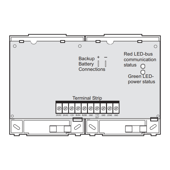
Figure 1
describes the power supply main components.
Figure 1. Power supply main components
Installation
Use the following guidelines for installing the power supply.
Guidelines
•
Up to 16 SuperBus 2000 devices can be connected to
Concord 4/Concord Express V4 panels (touchpads,
receivers, transceivers, HIMs, HOMs, ESMs, etc.).
P/N 466-2185 • REV B • January 2011
2000 digital data bus. The
®
Red LED-bus
Backup
communication
Battery
status
Connections
Green LED-
power status
Terminal Strip
•
The power supply AC transformer must be plugged into an
AC outlet that is not a ground fault interrupt circuit (GFIC)
or controlled by a switch.
•
When mounting the power supply inside the panel cabinet,
the backup battery can also be stored inside the panel
cabinet.
•
When mounting the power supply in a separate enclosure,
the maximum wire length from the power supply bus and
power connections to the panel is 4,000 feet.
•
When mounting the power supply in a separate enclosure,
the power supply mounting location should be determined
by the wire runs needed to provide power to devices with
minimal loss on the +12V OUT wire.
maximum wire runs between the power supply +12V OUT
terminal and the devices it will power.
Table 1. Maximum +12V OUT wire length
Gauge
Maximum wire length from power supply +12V
OUT terminal
22
100 feet
18
200 feet
16
350 feet
14
550 feet
•
For large installations with long wire runs, power supply
location is important. The total system wiring length (all
partitions) for all bus devices connected to a Concord 4/
Concord Express V4 panel must not exceed 4,000 feet.
This not only includes the power supply bus and power
connections to the panel, but also any bus devices you
may connect to the power supply. For example, touchpads
and other bus devices in a remote partition should be
connected to the power supply rather than running the
wires all the way to the panel
Table 1
shows the
(Figure
2).
1
Advertisement
Table of Contents

Related Manuals for Interlogix SuperBus 2000


Summary of Contents for Interlogix SuperBus 2000
- Page 1 (Figure Guidelines • Up to 16 SuperBus 2000 devices can be connected to Concord 4/Concord Express V4 panels (touchpads, receivers, transceivers, HIMs, HOMs, ESMs, etc.). P/N 466-2185 • REV B • January 2011...
- Page 2 Remove the power supply circuit board from the plastic mounting plates. Slide the top of the backplates onto the left and center module mounting clips on the panel cabinet (Figure SuperBus 2000 2-Amp Power Supply 600-1019 Installation Instructions...
- Page 3 Run a 2-conductor, 18-gauge stranded wire from the power supply to the AC transformer location. Feed all wires through the knockouts and secure the cabinet to the wall with the included screws. SuperBus 2000 2-Amp Power Supply 600-1019 Installation Instructions...
- Page 4 2. Power supply battery needs charging. the tool-free area, contact your dealer. Battery may need at least 4 hours to fully charge. Copyright © 2011 Interlogix, a UTC Fire & Security Company. All rights reserved. System touchpads 1. Check that power supply transformer is display AUX AC plugged into outlet.
Need help?
Do you have a question about the SuperBus 2000 and is the answer not in the manual?
Questions and answers