Advertisement
Quick Links
WARNINGS AND CAUTIONS:
• To be installed and/or used in accordance with appropriate electrical codes and regulations.
• If you are unsure about any part of these instructions, consult an electrician.
• Leviton electronic countdown timer switches are not compatible with standard 3-way or 4-way switches. They must be used with compatible
Vizia +
ON/OFF remote switches.
®
• Recommended minimum wall box depth is 2-1/2".
TOOLS NEEDED TO INSTALL YOUR TIMER SWITCH
Slotted/Phillips Screwdriver
Electrical Tape
Pencil
Cutters
Changing the color of your device:
Your device may include color options. To change color of the face,
proceed as follows:
Line up tabs and
Push in side
press in sides one
at tab to release
at a time to attach
MAXIMUM LOAD PER TIMER FOR MULTI-DEVICE INSTALLATIONS
Load
Single
Two Devices
More than 2 devices
Resistive Load
20A (2400W)
16A (1920W)
16A (1920W)
Incandescent Load
1800W
1800W
1800W
Inductive Load
20A
16A
16A
Motor Load
1HP
1HP
1HP
INSTALLING YOUR TIMER SWITCH
NOTE: Use check boxes
when Steps are completed.
WARNING:
Step 1
TO AVOID FIRE SHOCK OR DEATH; TURN
OFF POWER at circuit breaker or fuse and test that power is
off before wiring!
OFF
ON
OFF
ON
OFF
ON
OFF
ON
OFF
ON
OFF
ON
OFF
ON
OFF
ON
OFF
ON
OFF
ON
OFF
ON
OFF
ON
Identifying your wiring application (most common):
Step 2
NOTE: If the wiring in your wall box does not resemble any of
these configurations, consult an electrician.
Single Pole
3-Way
1. Line (Hot)
1. Line or Load (see
2. Neutral
IMPORTANT instruction)
3. Ground
1
2
2
2. Neutral
1
4. Load
3. Ground
3
4. First Traveler – note color
3
4
4
5
5. Second Traveler – note
color.
NOTE: For matching remote w/LEDs installation,
the First Traveler becomes Line Hot.
Single Pole (One location) or 3-Way (Multi-location)
IMPORTANT: For 3-Way applications, note that one of the screw terminals
from the old switch being removed will usually be a different color (Black)
or labeled Common. Tag that wire with electrical tape and identify as the
Pliers
common (Line or Load) in both the switch wall box and remote wall box.
Ruler
Preparing and connecting wires:
Step 3
Pull off pre-cut insulation from timer switch leads. Make sure
that the ends of the wires from the wall box are straight (cut if
necessary). Remove insulation from each wire in the wall box
as shown:
Cut
(if necessary)
For non-standard wiring applications, refer to
Wire Nut and Connector Size Chart
WIRE CONNECTOR / # OF COND. COMBINATION CHART
1 - #12 w/ 1 to 3 #14, #16 or #18
2 - #12 w/ 1 to 2 #16 or #18
1 - #14 w/ 1 to 4 #16 or #18
2 - #14 w/ 1 to 3 #16 or #18
• Make sure that the ends of the wires from the wall box are
straight (cut if necessary).
• Remove insulation from each wire in the wall box as shown.
• For Single-Pole Application, go to Step 4a.
• For 3-Way Coordinating Remote Switch (no LEDs) Application, go to Step 4b.
• For 3-Way Matching Remote Switch (with LEDs) Application, go to Step 4c.
Single Pole Wiring Application:
Step 4a
Black
1
White
2
4
Red
3
Green
Insulating label:
This wire is used in 3-way installations only.
For single pole installations, do not remove this insulating label.
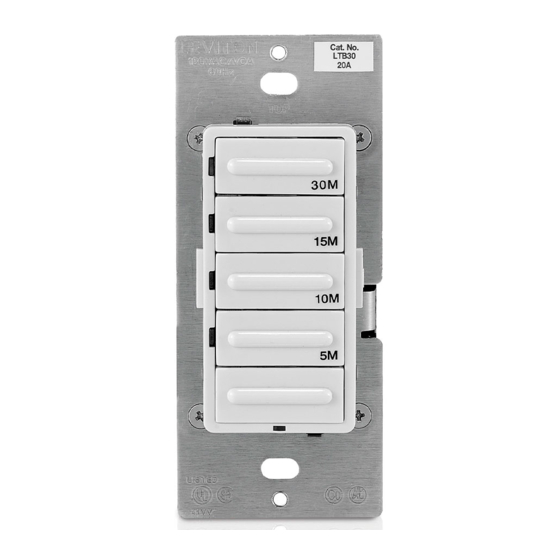
Electronic Countdown Timer Switch
Cat. No. LTB15, LTB30, LTB60, LTB02, LTB12 Lighted
20A Resistive/Inductive, 1800W Incandescent, 1HP
120VAC, 60Hz
INSTALLATION INSTRUCTIONS
WARNINGS AND CAUTIONS:
• Disconnect power at circuit breaker or fuse when servicing, installing or removing fixture.
• Use only one (1) Leviton electronic countdown timer switch in a multi-location circuit with up to 9 coordinating remote switches
without LEDs or up to 4 matching remote switches with LEDs.
• Maximum wire length from timer switch to all installed remote switches cannot exceed 300 ft (90 m).
• Use this device only with copper or copper clad wire only.
Step 4a cont'd
White
Green
Ground
Black
Load
Strip Gage
5/8"
(measure bare
(1.6 cm)
wire here)
White
WIRING TIMER SWITCH:
Connect wires per WIRING DIAGRAM as follows:
• Green or bare copper wire in wall box to Green lead.
• Line Hot wall box wire to Black lead.
• Load wall box wire to Red lead.
• Line Neutral wall box wire to White lead.
• Timer Switch Yellow/Red lead should have Red insulation label affixed.
• Proceed to Step 5.
3-Way Wiring with Vizia + Coordinating Remote
Step 4b
Switch (no LED) Application:
Coordinating Remote Switch
WH
BK
1
3
5
Yellow/Red
Step 4b cont'd
Timer Switch
Coordinating Remote Switch (no LED)
Black
Hot (Black)
Bla c k
Red
Yellow/Red
Line
Insulating
Load
Label
120 VAC, 60Hz
White
Neutral (White)
WIRING TIMER SWITCH:
Connect wires per WIRING DIAGRAM as follows:
NOTE: The timer switch must be installed in a wall box that has a Line
Hot connection.
NOTE: Maximum wire length from timer switch to all installed remote
switches cannot exceed 300 ft (90 m).
• Green or bare copper wire in wall box to Green lead.
• Line Hot (common) wall box wire identified (tagged) when removing
old switch to Black lead.
• First Traveler wall box wire to Red lead (note wire color).
• Remove Red insulating label from Yellow/Red lead.
• Second Traveler wall box wire to Yellow/Red lead (note wire color).
This traveler from the timer switch must go to the terminal screw on
the remote switch marked "YL/RD".
• Line Neutral wall box wire to White lead.
Timer Switch
WIRING VIZIA
Connect wires per WIRING DIAGRAM as follows:
Black
NOTE: "BK" and "RD" terminals on coordinating remote switch are
1
unused. Tighten both screws.
NOTE: Maximum wire length from timer switch to last remote switch
2
White
2
is 300 ft (90 m).
• Green or bare copper wire in wall box to Green terminal screw.
Yellow/Red
4
5
• Load wall box wire identified (tagged) when removing old switch to
Red
4
First Traveler (note color as above).
Green
• Second Traveler wall box wire (note color as above) to terminal
3
screw marked "YL/RD". This traveler from the remote switch must go
to the Yellow/Red lead of the timer switch.
• Remove White insulating label from terminal screw marked "WH".
• Line Neutral wall box wire to terminal screw marked "WH".
• Proceed to Step 5.
PK-93796-10-00-2A
Timer Switch
Hot (Black)
WH
BK
WH
BK
(u n used )
Green
Green
Ground
Ground
RD
RD
YL/RD
YL/RD
Line
(u n used )
120VAC, 60Hz
Neutral (White)
+
COORDINATING REMOTE SWITCH:
Advertisement

Related Manuals for Leviton DECORA LTB02


Summary of Contents for Leviton DECORA LTB02
-
Page 1: Installation Instructions
• To be installed and/or used in accordance with appropriate electrical codes and regulations. • If you are unsure about any part of these instructions, consult an electrician. • Leviton electronic countdown timer switches are not compatible with standard 3-way or 4-way switches. They must be used with compatible Vizia + ON/OFF remote switches. - Page 2 years.
Need help?
Do you have a question about the DECORA LTB02 and is the answer not in the manual?
Questions and answers