Advertisement
Quick Links
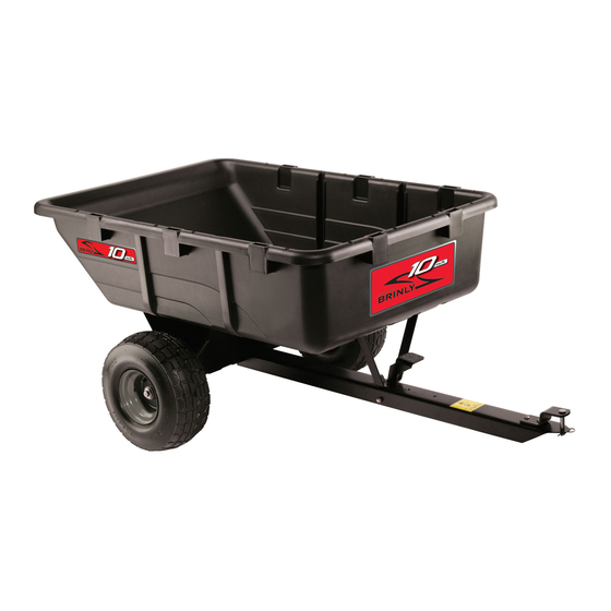
OWNER'S MANUAL
P O L Y C A R T , 1 0 C U B I C F O O T
MODEL:
P C T - 1 0 1 B H
P C T - 1 0 1 B H C
P C T - 1 0 1 B H C - A
P C T - 1 0 1 B H E X P
• Assembly
• Installation
• Operation
• Repair Parts
This utility cart is designed
for use with lawn tractors and
lawn and garden tractors.
Visit us on the web!
www.brinly.com
English Manual
Call Customer Service, Toll-Free: 877-728-8224
Important: This manual contains information for the safety
of persons and property. Read it carefully before
assembly and operation of the equipment!
1
English, Spanish &
French Manual
1008577ALL-E
Advertisement

Related Manuals for Brinly PCT-101BH


Summary of Contents for Brinly PCT-101BH
- Page 1 Call Customer Service, Toll-Free: 877-728-8224 Important: This manual contains information for the safety Visit us on the web! of persons and property. Read it carefully before www.brinly.com assembly and operation of the equipment! English Manual 1008577ALL-E...
- Page 2 INTRODUCTION AND SAFETY ================================================================================================== CONGRATULATIONS on your new Brinly-Hardy Cart! This accessory has been designed, engineered and manufactured to give you the best possible dependability and performance. Should you experience any problem you cannot easily remedy, please do not hesitate to contact our knowledgeable customer service department toll-free at 1-877-728-8224.
- Page 3 SAFETY ================================================================================================== WARNING AVOID INJURY FROM EXPLOSION • Do not place gas container in cart when filling RIDERS CAN FALL OFF AND BE KILLED • No riders in cart B-7084 GENERAL SAFETY NOTES ( Operation ) Caution should be taken when towing and/or using any attachment. This attachment combined with the weight distribution, turning radius, and speed of towing vehicle can result in severe injury or death to operator, damage to towing vehicle, and/or attachment if not used properly.
- Page 4 Please call our customer Service Department, Toll Free: 877-728-8224 • Do not carry passengers. or customerservice@brinly.com • Do not let anyone, especially children, ride in/on this attachment, the towing vehicle or hitch bracket. • Riders are subject to injury such as being struck by foreign object and/or being thrown off during sudden starts, stops and turns.
- Page 5 COMPONENT VIEW AND REFERENCE LIST ================================================================================================== (x10) (x10) (x2) (x2) (x2) (x8) (x2) Ref. Description Part Number qty. Ref. Description Part Number qty. E Ring, 3/4" B-4305 Poly Bed 1008574 Warning Label B-7084 Machine Bushing B-5606 Wheel 1008575 Hex Hd Bolt, 3/8" x 3-3/4" B-6298 Foot Pedal 1008604...
- Page 6 HARDWARE IDENTIFIER ================================================================================================== DO NOT RETURN PRODUCT IF YOU ARE MISSING PARTS. Illustrations on this page Please call: 1 (877) 728-8224 are to scale for faster identification of hardware during assembly. Nut: Hex Head Retaining Ring, E 3/4” (x2) ... . 5/16”...
- Page 7 ASSEMBLY ================================================================================================== Assembly Step 1 Install Axle Support Hardware Panel 1 1. Position the Axle Support (20) over slotted holes over the cart bed (1). 2. Secure in place from inside the cart bed (1) with one 5/16 x 1" Round Head Screw (7), and 5/16"...
- Page 8 ASSEMBLY ================================================================================================== Assembly Step 3-A 1. Align the cart foot pedal (4) through slot in drawbar (21) with the notch in the foot pedal oriented towards the raised tongue on the drawbar. See illustration. 2. While holding the foot pedal (4) in place, flip the drawbar (21) over.
- Page 9 ASSEMBLY ================================================================================================== Assembly Step 3-C Hardware Panel 3 continue running the 3/8 x 3-3/4 in. bolt (15) through the foot pedal (4). Between the foot pedal (4) and drawbar, add one 3/8 in. keps nut (16) to the bolt (15) as illustrated. Finally, run the end of the bolt (15) through the other side of the drawbar (21).
- Page 10 ASSEMBLY ================================================================================================== Assembly Step 4 Hardware Panel 4 Hook one end of the latch spring (17) through the small hole at the base of the foot pedal (4). Hook the other end of the latch spring (17) through the drawbar (21) as illustrated. Assembly Step 5 Install Clevis Hardware Panel 5...
- Page 11 ASSEMBLY ================================================================================================== Assembly Step 6 A. Align the drawbar (21) as illustrated here. NOTE: Tighten all hardware installed on Steps 1 and 2. B. Align and start running the axle (19) through the first three slots of the Axle Support (20). Push the Axle (19) through the holes at the base of the drawbar (21), then continue through the rest of the Axle Support (20).
- Page 12 ASSEMBLY ================================================================================================== Assembly Step 7 Gently flip the cart over. Assembly is complete! USE AND CARE MODEL: P C T - 1 0 1 B H C A R T U S E & C A R E S E C T I O N MAINTENANCE SPECIFICATIONS •...
- Page 13 USE AND CARE ================================================================================================== INSTALLING THE CART UNLOADING THE CART CAUTION: AVOID INJURY! Keep body parts away from under Drawbar and Bed. CAUTION: Take care when dumping the Bed. An unevenly distributed load in the Bed could cause the Bed to dump quickly (Example: load 1.
- Page 14 SAFETY NOTES: Maximum load for cart is 650 lbs. • Read and follow the operating instructions for your machine and your Brinly Poly cart. AVOID OVERFILLING THE CART • The stake side kit is for transporting light debris only, such as leaves, straw, This can cause the towing vehicle to lose traction and and sticks.
- Page 15 USE AND CARE ================================================================================================== DIY: DIRECTIONS FOR CUSTOM-BUILT SIDE STAKES, Continued SHOPPING LIST / MATERIALS NEEDED: Step 1. Drill two 9/32" holes in each 13-1/2" Ref. Description: Qty. side stake (1), located as illustrated here. Long Pressure 8” Sand down the 3/4" Treated Wood: 13-1/2”...
- Page 16 USE AND CARE ================================================================================================== DIY: DIRECTIONS FOR CUSTOM-BUILT SIDE STAKES, Continued Step 4. Building the Stake Side Rails Assemble the side stakes as illustrated here. Step 5. Drilling Location (if needed) Some cart pockets may have a hole provided at the base of each pocket OR a 1/8”...
- Page 17 180° dump, ensuring unloading is pin for an extra-strong, always a breeze. convenient upgrade. - Diameter: 1/2” - Pin Length: 3” NOTE: Additional accesories are also available in our Parts Store online: shop.brinly.com English Manual 1008577ALL-E...
- Page 18 MANUFAcTURER’S LIMITED WARRANTY CARTS The limited warranty set forth below is given by Brinly-Hardy Company with respect to new merchandise purchased and used in the United States (its possessions and territories) and Canada. Brinly-Hardy company warrants the products listed below against to use this product.
Need help?
Do you have a question about the PCT-101BH and is the answer not in the manual?
Questions and answers