Table of Contents
Advertisement
Quick Links
Advertisement
Table of Contents

Related Manuals for AES 7007

Summary of Contents for AES 7007
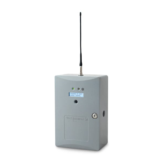
- Page 1 AES 7007 Security Subscriber Installation, Operation and Programming Manual AES Corporation 285 Newbury Street Peabody, MA 01960 USA Tel (978) 535-7310 • Fax (978) 535-7313 www.aes-corp.com Copyright © 2022 AES Corp. All Rights Reserved Part No. 40-7007 Rev. 2B, 4/9/2022...
- Page 2 AES 7007 Security Subscriber This page deliberately left blank Part No. 40-7007 Rev. 2B, 4/9/2022...
-
Page 3: Table Of Contents
External Antenna ....................... 18 Antenna Selection ......................18 Coaxial Cable and Connector Selection ................18 Antenna Location ......................18 Antenna Installation .....................18 Antenna and Surge Suppressor Grounding ..............19 System Configuration......................19 Compatible Device List ....................19 Digital Communicator .....................19 Part No. 40-7007 Rev. 2B, 4/9/2022... - Page 4 ALM LED Blink Pattern Chart ...................32 8.18 System Messages ......................33 Display Operation ....................33 System Status Display and 7007 Version Number ..........33 Unit ID and Serial Number ..................33 Link Layer and NetCon ....................33 Zone Input Programming ..................34 Network Connectivity Status ..................35 Battery and AC Power Status ..................35...
- Page 5 Download Support Files (from subscriber to PC) ............41 Restart System ......................41 Flexible Power Option ....................... 41 Reporting ........................... 44 11.1 AES Mesh Network .......................44 11.2 Compatible Receiver .....................44 Testing ..........................44 Maintenance ........................44 Troubleshooting ........................ 45 Repair Information ......................45 Part No. 40-7007 Rev. 2B, 4/9/2022...
- Page 6 Antenna and Surge Suppressor Grounding............19 Figure 7. System Configuration Options ................20 Figure 8. Sole Path (Single Reporting) ................20 Figure 9. Single Reporting with Backup ................21 Figure 10. Dual Reporting .....................21 Figure 11. Field Wire Connections ..................22 Part No. 40-7007 Rev. 2B, 4/9/2022...
-
Page 7: Safety Considerations
• AES assumes no responsibility for the equipment’s failure to operate. AES's sole responsibility is to repair or replace any AES device found to be defective during the warranty period. Exposing the Subscriber electronics to water or moisture environments, such as rain, shower, bath, pool, sauna, •... - Page 8 Enclosure Material: Molded UL-recognized polymer Finish Color: Gray Inputs Alarm Signal Inputs: • 7007 Zone Input – four each EOL resistor type – All inputs supervised with trouble and restore • Alarm Panel Siren/Bell Input • Alarm Panel Phone Line Input: 7094A IntelliPro Module •...
-
Page 9: Pre-Installation
A separately purchased remote antenna may be used with the 7007 unit in UL installations. See External Antenna Pg. 18 for information on antennas available from AES. The frequency range is 450–470 MHz. Contact the factory at (800) 237-6387 or info@aes-corp.com for other frequencies. -
Page 10: Requirements
10. Wiring Specifications The plug-in transformer must be placed in AES’s Transformer Enclosure (P/N 1640-ENCL) for UL compliant installations. If required for certain installations, the wiring from the low-voltage output of the plug-in transformer to the subscriber enclosure must be enclosed in conduit. -
Page 11: Table 1. Battery Size Requirements
Size See Current Consumption under Technical 7007 7 Ah Specifications on page 8. 7007 See Current Consumption under Technical 10 Ah Specifications on page 7 and the 7094A 7094A IntelliPro Installation and Operation Manual. Part No. 40-7007 Rev. 2B, 4/9/2022... -
Page 12: Installation
7007 Installation Table 2 lists tasks to perform when installing the AES 7007 subscriber. Use the list to verify that installation tasks have been identified and completed. Tasks do not have to be performed in the order listed unless specifically identified. -
Page 13: Enclosure Installation
Locally Announce AC Failure Suppress Charger Fault Report Enable Repeating System Operation System Messages Display Operation System Status Display and 7007 Version Number Subscriber ID and Serial Number Link Layer and NetCon Route Table Zone Input Programming Network Connectivity Status... -
Page 14: Mounting The Enclosure
(on request, available as a kit) extends in the rear of the back box to detect removal from a mounting surface. See Installation on page 46 for instructions. Enclosure Back Box Tamper Switch To remove electronic boards mounted in the enclosure, perform the following steps for the boards installed. Part No. 40-7007 Rev. 2B, 4/9/2022... -
Page 15: Removing The 7094A Intellipro
Plug-In Transformer WARNING! Turn off or disconnect all power before attempting to connect the 7007 subscriber. Do NOT apply power until all accessories are properly connected. For UL compliant installation, use only one of the Class 2 Direct Plug-in Transformers listed in the table below:... -
Page 16: Earth Ground Connection
‒ • Earth ground and backup battery ( ) are not separate connections in the 7007 Subscriber. Connect a suitable gauge ground wire as specified in the applicable electrical code to the wire under the green • hex nut on the threaded metal post, as shown in the photo above. -
Page 17: Battery Replacement
Battery Replacement Instructions on Pg. 45 for details. Battery Only Restart The 7007 subscriber without AC power (for test or diagnostic purposes) will power up and self-test with only the battery connected. Battery Supervision When AC power is present, the battery is tested at approximately 30-second intervals. -
Page 18: External Antenna
Antenna Selection A remotely mounted external antenna may be required for optimal performance on the mesh network, depending on installation location requirements or conditions. Contact AES Corporation for additional antennas that may be used with the 7007 Security Subscriber unit. -
Page 19: Antenna And Surge Suppressor Grounding
Antenna and Surge Suppressor Grounding A protective surge suppressor (AES Model 7230) must be installed in line with any type of remotely installed outdoor antenna, as shown in the diagram below. The surge suppressor and outdoor antenna must be earth grounded. For U.S. -
Page 20: System Communication Configuration
Figure 7. System Configuration Options System Communication Configuration Sole Path (Single Reporting) utilizes either the AES mesh radio network or a TCP/IP broadband connection to deliver messages from the subscriber to the central monitoring station. Figure 8. Sole Path (Single Reporting) -
Page 21: Figure 9. Single Reporting With Backup
AES 7007 Security Subscriber Single Reporting with Backup utilizes either the AES mesh radio network, or a TCP/IP broadband connection, to deliver messages from the subscriber to the central monitoring station. The Backup Reporting path works when the Primary Reporting path is down. -
Page 22: Figure 11. Field Wire Connections
Selecting Power Option No. 4 (12 V DC only) using the 7085UE5 transceiver results in power output of 50 to 60% of full radio capacity. Important! Wiring must be enclosed in conduit when used in UL compliant installations. Part No. 40-7007 Rev. 2B, 4/9/2022... -
Page 23: Trouble Output
If DHCP is not available, the IP address is set to 169.254.100.1. Logging In Connecting to the 7007 configuration page requires a login. Enter the IP address of the subscriber into a web browser, then enter your username and password at the login screen. The default username and password are admin... -
Page 24: Security Subscriber Interface
Configuration settings are made and changed using either the dropdown or slider switch controls in the window. The dropdown provides a list to select from: The slider switch provides one of two values to select: Part No. 40-7007 Rev. 2B, 4/9/2022... -
Page 25: Saving Configuration Changes
The Status window displays changes: View 7007 Subscriber Software Version The 7007 software version is visible in the System tab under the System Firmware Upgrade panel. Select the System tab, as shown in the following figure: The version number is displayed in the System Firmware Upgrade section:... -
Page 26: Change Login Password
(refer also to Sole Path (Single Reporting) diagram on page 20) • Radio and Internet: Radio Configuration Central Receiver Configuration and Subscriber IP Address under • Advanced Configuration (refer also to the Dual Reporting diagram shown on page 21) Part No. 40-7007 Rev. 2B, 4/9/2022... -
Page 27: Radio Configuration
Valid values are 0000 to FFFF. Note: The code must match the AES 7170 IP-Link cipher code for the network that the subscriber is to join. The subscriber will not join the mesh network if the cipher code is incorrect. -
Page 28: Advanced Configuration
Time-to-Live settings are for managing the performance of the AES mesh network. TTL is the length of time a packet message transmission for a specific setting is retried by a subscriber in the AES mesh network. The subscriber will stop attempting to transmit the packet when the TTL limit has expired. -
Page 29: Zone Input Configuration
8.11 Zone Input Configuration Zone input for the Model 7007 and the 7094A IntelliPro are configured under the Accessories tab. You can verify that a 7094A IntelliPro is installed by selecting the Status tab and checking the Hardware panel. To configure zone inputs on the 7007 click the Accessories tab shown below:... -
Page 30: Alarm Panel Siren Input Options For Zones 5 And 6
Temporal/Pulse alarm pattern Steady/Even alarm pattern • Connect the Alarm Panel Siren terminals to the 7007 subscriber siren input terminals. 8.12 Consecutive AT Events Set Consecutive AT Events to Yes for verbose reporting of alarm and trouble messages. This means that alarms and trouble will be sent continuously alarm-trouble-alarm-trouble. -
Page 31: 7094A Intellipro Configuration
Panel Interface: Displays ECP Bus or DSC Mode for the keypad interface protocol present. Panel Account Number: Enter the panel account number. • Keypad Address: The keypad address for the 7007 subscriber must be set to 18 for correct operation, • and the address must be enabled at the Alarm panel for operation. -
Page 32: Status Led Indicators
AES 7007 Security Subscriber 8.17 Status LED Indicators The four LED indicators on the Model 7007 main circuit board show the system status. The LEDs are located in the lower left corner of the circuit board above the J6 connector: Table 3. -
Page 33: System Messages
System Status display screen. System Status Display and 7007 Version Number When the Model 7007 is operating normally, the Normal System Status screen is shown in the LCD. The model number, software version number, and status message are displayed as shown: 7007 BURG VER:X.XXX... -
Page 34: Zone Input Programming
Inverted, B for Bypass, O for Normally Open and C for Normally Closed. For Zone 5 and Zone 6 status values are: B for Bypass, E for Even, and T for Temporal. ZONE:1-S 2-B 3-B 4-O ZONE:5-B 6-B Press the MENU button to view the next status message. Part No. 40-7007 Rev. 2B, 4/9/2022... -
Page 35: Network Connectivity Status
The interface from the subscriber to the alarm panel is shown. Values are ECP KEYPAD, DSC KEYPAD, or 7094A. Panel Interface: KEYPAD NOTE: Only one Panel Interface may be used at a time. Press the MENU button to view the next status message. Part No. 40-7007 Rev. 2B, 4/9/2022... -
Page 36: 7094A Intellipro Software Version
Single fault – A single fault condition is shown on the display, and the subscriber buzzer sounds: 7007 VER:X.XXX Status: AC FAIL When the single fault condition clears, the cleared fault message no longer displays and the buzzer stops sounding. Part No. 40-7007 Rev. 2B, 4/9/2022... -
Page 37: Disable On Board Buzzer
Subscriber Status Check General Information about the Model 7007 subscriber is shown from the Status tab. The Status page shows any faults, as well as the unit (subscriber) RF ID, Link Layer, and NetCon values: If faults are present, they are displayed. -
Page 38: Hardware
To access these features, select the Tools tab as shown in red below: Text Message A text message can be sent from the 7007 subscriber to the central monitoring station. Messages from the central station can also be received. In the Text Messages over RF panel, use the message line at the bottom of the panel to enter the message. Messages have a 200-character limit. -
Page 39: Alarm History
AES 7007 Security Subscriber Alarm History Messages sent from the alarm panel through the Model 7007 subscriber are displayed in the Alarm History user interface panel. RF Traffic RF Traffic Receive and Transmit traffic to/from the subscriber can be viewed using the panel. -
Page 40: System Settings
Setting information can be downloaded from the subscriber. Select the RF Config or IntelliPro Config button and click the Download button. Upload Preconfigured Settings To upload subscriber settings to the Model 7007, click Choose File, select the file, and click Upload. Part No. 40-7007 Rev. 2B, 4/9/2022... -
Page 41: Reset To Default Configuration
Refer to the diagram shown in the section on page 10 for supply and connection requirements. Power Options Important! When using this selection, 16.5 V AC is the primary power source and the battery is the secondary power source. Part No. 40-7007 Rev. 2B, 4/9/2022... - Page 42 . The report delay is the time that must pass before the Model 7007 Subscriber will send an AC failure or AC restoral message. This feature helps prevent mesh network congestion in an area where many Subscribers have an AC power outage at the same time.
- Page 43 DC Report Delay: DC Report Delay is active when Suppress DC Power Fault is set to No. The report delay is • the time that must pass before the Model 7007 subscriber will send a primary power failure or primary restoral message. This feature helps prevent mesh network congestion in an area where many subscribers experience a power outage at the same time.
-
Page 44: Reporting
When done with changes, click on the Save Changes button. 11. Reporting 11.1 AES Mesh Network The 7007 Subscriber can eliminate the need for POTS telephone lines by communicating with the 7705i MultiNet using the AES mesh radio network. 11.2 Compatible Receiver The 7007 Subscriber is compatible with the AES Corp. -
Page 45: Troubleshooting
AES. For information on returning units, see the Return Material section at the end of the Warranty. 15. Repair Information Other than the backup battery, the 7007 Subscriber contains no user serviceable parts. 16. Contact Information AES Corporation 285 Newbury Street Peabody, Massachusetts 01960 USA Website: http://www.aes-corp.com... -
Page 46: Enclosure Back Box Tamper Switch Installation
10. Connect the positive battery lead (red) to the battery. 11. Perform subscriber power-up and self-test procedure. 18. Enclosure Back Box Tamper Switch Installation The Model 7007 has mounting space for a back box tamper switch which can detect removal of the enclosure mounted to a wall surface. Required: Back Box Tamper Switch Kit AES P/N 70-TSWK 5/32 in. - Page 47 Adjust the plunger switch length to ensure contact when the enclosure is pressed against the mounting surface. Wire the switch to the required zone input on the Model 7007 mainboard. When subscriber enclosure is mounted and powered up, configure the enclosure tamper zone input.
-
Page 48: Warranty
Certain AES Products include software, protocols and other proprietary and confidential technology and trade secrets of AES which are incorporated in or provided with AES Products solely for use in conjunction with and in order to operate AES Products (“Licensed Technology”). AES grants the original purchaser a non-exclusive license to use such Licensed Technology solely in connection with the use and operation of AES Products and for no other purpose or use whatsoever.
Need help?
Do you have a question about the 7007 and is the answer not in the manual?
Questions and answers