Table of Contents
Advertisement
Available languages
Available languages
Quick Links
MANUALE DI SISTEMA RX 4000
RX 4000
Sistema di Evacuazione EN 60849
Manuale di sistema
(Issued: Gennaio 2009 - Versione 1.9)
RCF SpA
Via Raffaello, 13 - 42100
Mancasale Reggio Emilia - Italia
This document may be duplicated or otherwise used or its contents made known to third parties only with
permission of the originator or other authorized people.
Infringements constitute an offence and are subject to claim for damages. All rights reserved for patenting or
utility model registration.
Gennaio 2009
Versione 1.9
Page 1 di 87
Advertisement
Table of Contents

Subscribe to Our Youtube Channel
Related Manuals for RCF RX 4000


Summary of Contents for RCF RX 4000
- Page 1 MANUALE DI SISTEMA RX 4000 RX 4000 Sistema di Evacuazione EN 60849 Manuale di sistema (Issued: Gennaio 2009 - Versione 1.9) RCF SpA Via Raffaello, 13 - 42100 Mancasale Reggio Emilia - Italia This document may be duplicated or otherwise used or its contents made known to third parties only with permission of the originator or other authorized people.
- Page 2 MANUALE DI SISTEMA RX 4000 Contenuti AVVERTENZE PER LA SICUREZZA Attenzione Normative CE DESCRIZIONE GENERALE SISTEMA RX 4000 Introduzione Composizione sistema RX 4000 Glossario e Abbreviazioni DESCRIZIONE COMPONENTI SISTEMA RX 4000 CP 4100 - Unità Centrale 3.1.1 Pannello Posteriore CP 4100 3-10 3.1.2...
- Page 3 MANUALE DI SISTEMA RX 4000 Menu Principale 4-51 4.1.1 Icone display 4-51 4.1.2 Mute Buzzer 4-51 4.1.3 View Fault 4-52 4.1.4 Eject Fault Report Page 4-52 4.1.5 About..4-52 √ to log in 4.1.6 4-53 4.1.7 Edit User 4-54 4.1.8...
- Page 4 L’installazione e l’utilizzo errati del prodotto esimono la RCF S.p.A. da ogni responsabilità. ATTENZIONE: Per prevenire i rischi di fiamme o scosse elettriche, non esporre mai questo prodotto alla pioggia o all'umidità.
- Page 5 Verificare inoltre l’idoneità del supporto (parete, soffitto, struttura ecc., al quale è ancorato il prodotto) e dei componenti utilizzati per il fissaggio (tasselli, viti, staffe non fornite da RCF ecc.) che devono garantire la sicurezza dell’impianto / installazione nel tempo, anche considerando, ad esempio, vibrazioni meccaniche normalmente generate da un trasduttore.
- Page 6 • E4 (ambiente EMC controllato, per es.: studio di trasmissione) NOTE IMPORTANTI Un uso improprio di apparecchi HF come radio ricetrasmittenti e cellulari possono causare interferenze radio sui dispositivi RCF S.p.A.. Per una funzionalità più affidabile si consiglia vivamente di non utilizzare radio ricetrasmittenti e cellulari vicino agli apparecchi! Gennaio 2009 Versione 1.9...
- Page 7 16 zone di diffusori (espandibile a 64 zone). Essendo un sistema di allarme vocale ed annunci, l’RX 4000 può essere collegato al sistema di rilevamento d’incendio di qualsiasi produttore tramite collegamenti monitorati dai suoi circuiti di rilevamento.
- Page 8 Canale CI16 LI 4116 Modulo con 16 ingressi logici per delle funzioni di servizio Scheda interfaccia RS 232C interna al telaio RX 4000 per il collegamento a PC esterno e ingresso 24vdc Digitale / Analogico IT 4133 Modulo ingresso per console digitali BM 4764, BM 4748, BM 4732, BM 4716 e per connettere tra loro fino a 4 unità...
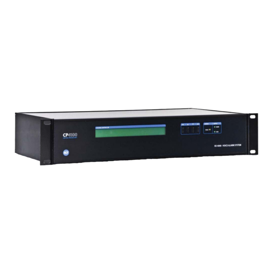
- Page 9 Descrizione Componenti sistema RX 4000 CP 4100 - Unità Centrale L’unità centrale RX 4000 è composta dalla scheda CPU (slot 1) che controlla il sistema, fino a 8 schede d’ingresso audio e fino ad 8 schede d’uscita audio. La scelta delle schede d’ingresso e d’uscita dipende dall’applicazione e dalle necessità...
- Page 10 MANUALE DI SISTEMA RX 4000 3.1.1 Pannello Posteriore CP 4100 L’unità centrale CP 4100 è dotata di due connettori posizionati sul lato sinistro dell unità, uno per il collegamento del PC esterno e l’altro per l’alimentazione 24 V dc. L’interfaccia seriale tra il PC e l’unità centrale CP4100 è RS232 a 19200 Baud, 8 Bit, 1 Bit di stop, ”No parity”.
- Page 11 MANUALE DI SISTEMA RX 4000 Schema a blocchi: Contrast =Trimmer per la regolazione della luminosità del display Tone level = Trimmer per la regolazione livello del segnale di controllo 22 kHz (quando utilizzato) Reset= pulsante per il reset della scheda CPU Gennaio 2009 Versione 1.9...
- Page 12 MANUALE DI SISTEMA RX 4000 3.1.2 IT 4133 Scheda conessione console microfoniche ed interfacciamento tra unità centrai CP 4100 La scheda IT 4133 è usata per: • per collegare le console digitali BM4716, BM4732, BM 4748, BM4764 al CP4100; •...
- Page 13 MANUALE DI SISTEMA RX 4000 Schema a blocchi: Quando nel sistema sono previsti due o più CP4100, ogni CP 4100 deve avere lo stesso numero di schede IT 4133. Per il collegamento tra i CP4100, serve un cavo a 8 conduttori del tipo categoria 5 con connettori RJ45 collegati “pin to pin”...
- Page 14 MANUALE DI SISTEMA RX 4000 Per evitare dei disturbi sulla linea dati, è molto importante utilizzare le coppie intrecciate del cavo CAT5 come indicato nella seguente tabella: Connettore RJ45 superiore per uscite verso una scheda IT 4133 o HB4103 Pin 1 = Audio 1 + = filo bianco-arancio (in coppia con arancio)
- Page 15 MANUALE DI SISTEMA RX 4000 3.1.3 IB 4001FM Scheda ingresso microfonico Cambiare la foto ! Scheda ingressi audio di emergenza o generici che possono essere indirizzati su tre zone o gruppi di zone (o 1 zona + 2 comandi per messaggi), i comandi PTT, SW1, SW2 possono essere diagnosticati a distanza utilizzando delle resistenze da 6,8k da collegare fra i tre comandi ed il negativo GND.
- Page 16 MANUALE DI SISTEMA RX 4000 Schema a blocchi: Gennaio 2009 Versione 1.9 Page 16 di 87...
- Page 17 MANUALE DI SISTEMA RX 4000 3.1.4 VB 4134 Scheda Messaggi Presa 25 poli per il collegamento ad una porta parallela standard di un PC, per l’inserimento di messaggi audio sulla memoria flash interna della scheda VB 4134 (utilizzando l’apposito software).
- Page 18 MANUALE DI SISTEMA RX 4000 Schema a blocchi: 16 kHz 16 bit (buona qualità audio) 11 kHz 16 bit (discreta qualità audio) Gennaio 2009 Versione 1.9 Page 18 di 87...
- Page 19 MANUALE DI SISTEMA RX 4000 3.1.5 IB 4121/BGM Scheda ingresso per sorgente musicale Prese RCA di ingresso per il segnale audio stereo (o mono); i canali destro (R) e sinistro (L) sono miscelati internamente (tramite apposite resistenze). Sono presenti due interruttori per la regolazione del livello musica di sottofondo (1 e 2) e due comandi per l’attivazione (3-4)
- Page 20 MANUALE DI SISTEMA RX 4000 Schema a blocchi: Comandi di attivazione esterni 1= GND 2= Contatto segnalazione allarme da impostare sul software 3-4-5-6= Contatti per attivare le funzioni impostate nel menu ”Cause And Effects” Attenzione: i contatti in uscita e quelli d’attivazione sono riferiti a massa (GND).
- Page 21 Per evitare la segnalazione di allarme sul CP 4100, occorre collegare tra il pin CONTROL e il pin GROUND una resistenza da 6,8 kohm. Nota: se si utilizzano le schede RCF RB3300+SB3320 (necessarie per la sorveglianza degli amplificatori e delle linee altoparlanti), è possibile collegare questi pin ai contatti normalmente chiusi del relè...
- Page 22 MANUALE DI SISTEMA RX 4000 Schema a blocchi: La scheda OB 4102 ha le seguenti specifiche: Dimensioni: 155x80x25 mm Peso: 0,12 kg Alimentazione Ingresso : 20 ÷ 32 V dc Consumo: 16 mA Tensione massima opto-isolamento: 32 V dc Corrente massima diretta 25 mA Gennaio 2009 Versione 1.9...
- Page 23 MANUALE DI SISTEMA RX 4000 3.1.7 LI 4116 Scheda con 16 ingressi logici Connettore 37 poli femmina per il collegamento di 16 comandi di attivazione esterni (da impostare tramite software). L’attivazione del comando si ottiene con una tensione compresa fra 18 e 36 V dc collegata con le polarità indicate ed ai pin corrispondenti (vedi tabella).
- Page 24 MANUALE DI SISTEMA RX 4000 Schema a blocchi: La scheda LI 4116 ha le seguenti specifiche: Dimensioni: 155x80x25 mm. Peso: 0,12 kg Alimentazione Ingresso : 20 ÷ 32 V dc Alimentazione Uscita : 20 ÷ 32 V dc (fusibile: 500 mA)
- Page 25 MANUALE DI SISTEMA RX 4000 BM 4716, BM 4732, BM 4748, BM 4764 Basi Microfoniche Dalle basi microfoniche si possono inviare annunci in zone diverse (es. di un palazzo o di un complesso di costruzioni). Console digitale che dispone di 16-32-48-64 tasti funzione (inserzione zone), un tasto “ALL CALL”...
- Page 26 MANUALE DI SISTEMA RX 4000 Schema a blocchi: Gennaio 2009 Versione 1.9 Page 26 di 87...
- Page 27 Sul display delle console digitali all’accensione compare: nella riga superiore il nome impostato nell’apposito menu di configurazione, il cui accesso è consentito solo agli utenti “Supervisor” e “Engineer” (es. RCF REGGIO E. CE4122) nella riga sotto compare l’indicazione ٧ For Option .
- Page 28 > Panel Faults : Panel Healthy (se non ci sono guasti) > RCF REGGIO E. CE…. : System Healthy (se non ci sono guasti sul CP4100) > (Attenzione! Se ci sono altri CP4100 collegati vengono evidenziati di seguito) Per selezionare uno di questi menu utilizzare i tasti ▲▼.
- Page 29 MANUALE DI SISTEMA RX 4000 • About……. Premendo OK in corrispondenza di questa riga compaiono alcuni dati caratteristici della console: Product : Programable Paging Panel Internal Name : iMPC Version : 1.4.6 Processor MEGA128 Processor speed 16.000000MHZ • ٧ To log IN Selezionando OK in corrispondenza della riga ٧...
- Page 30 MANUALE DI SISTEMA RX 4000 3.2.3 Fire Officer Premere il tasto OK in corrispondenza dell’utente Fire Officer e impostare la password 3333 nel seguente modo: Enter PIN _ _ _ _ Premendo il tasto ▲ tre volte si visualizza il n° 3 come primo numero del PIN, poi selezionando il tasto OK si sposta la selezione sul secondo numero e ripetendo di nuovo tre volte il tasto ▲...
- Page 31 MANUALE DI SISTEMA RX 4000 3.2.4 Supervisor Premere il tasto OK in corrispondenza dell’utente Supervisor ed impostare la password 2222 nel seguente modo: Enter PIN _ _ _ _ Premendo il tasto ▲ due volte per selezionare la prima cifra 2 del PIN, poi premendo OK, si sposta la selezione sulla seconda cifra e, premendo di nuovo due volte il tasto ▲, si seleziona...
- Page 32 MANUALE DI SISTEMA RX 4000 • Edit Panel Details Selezionando con i tasti ▲▼ la riga Edit Panel Details e premendo il tasto OK si entra in una lista di 4 sottomenu che sono: Edit Panel Name Edit Keep Selects...
- Page 33 MANUALE DI SISTEMA RX 4000 Consente di attivare la comunicazione fra le apparecchiature digitali inserite nel sistema e la console stessa. Gli indirizzi da 1 a 4 si riferiscono all’indirizzo delle schede GPI (IT4133), mentre gli indirizzi da 5 a 8 sono relativi alle 4 console digitali che si possono collegare ad ogni singola scheda IT4133.
- Page 34 MANUALE DI SISTEMA RX 4000 3.2.5 Engineer Premere il tasto OK in corrispondenza dell’utente Engineer ed impostare la password 4444 nel seguente modo: Enter PIN _ _ _ _ Premendo il tasto ▲ quattro volte si visualizza il n° 4 come primo numero del PIN, poi tramite il tasto OK si sposta la selezione sul secondo numero e premendo di nuovo quattro volte il tasto ▲...
- Page 35 MANUALE DI SISTEMA RX 4000 • View Button Config Selezionando con i tasti ▲▼ la riga View Button Config e premendo il tasto OK, si apre una schermata con le impostazioni del tasto stesso. • Edit Radio Button Groups Selezionando con i tasti ▲▼ la riga Edit Radio Button Groups e premendo il tasto OK Si attivano due sottomenu che sono: Radio Button Groups : (1-16) ▲...
- Page 36 MANUALE DI SISTEMA RX 4000 Selezionare con i tasti ▲▼la voce che si desidera impostare e premere il tasto OK per confermare la scelta; a fianco dell’opzione scelta compare un simbolo ٧ di conferma. Premendo il tasto OK si accede anche alla seguente schermata: Chime Duration (0.0-8.0) ▲...
- Page 37 MANUALE DI SISTEMA RX 4000 • Engineering Functions Selezionando con i tasti ▲▼ la riga Engineering Functions e premendo il tasto OK, si entra in una lista di 6 sottomenu che sono: View Panel Status Test Mode Address Detected View EEPROM...
- Page 38 MANUALE DI SISTEMA RX 4000 3.2.6 User Premere il tasto OK in corrispondenza dell’utente USER 1 e impostare la password 0001 nel seguente modo: Enter PIN _ _ _ _ Premendo il tasto ▲ due volte si visualizza il n° 0 come primo numero del PIN, poi con il tasto OK si seleziona il secondo numero.
- Page 39 MANUALE DI SISTEMA RX 4000 BM 4601 - Base Microfonica La BM 4601 ha le seguenti specifiche: Livello di uscita: 750 mV. Filtri : 100 Hz +/- 12 dB; 1 kHz +/- 12 dB; 10 kHz +/- 12 dB Consumo: < 100 mA...
- Page 40 MANUALE DI SISTEMA RX 4000 Schema elettrico Gennaio 2009 Versione 1.9 Page 40 di 87...
- Page 41 MANUALE DI SISTEMA RX 4000 BM 4631WM – Pannello per vigili del fuoco / emergenze BM 4631WM ha le seguenti specifiche: Dimensioni 350 mm (a) x 200 mm (l) x 100 mm (p) Peso 3,5 Kg Alimentazione Ingresso : 20-32 Vdc (dalla scheda 1LS) Consumo: <...
- Page 42 MANUALE DI SISTEMA RX 4000 Fissaggio a muro PCB layout Gennaio 2009 Versione 1.9 Page 42 di 87...
- Page 43 MANUALE DI SISTEMA RX 4000 HB 4103/16 Modulo connessione basi microfoniche Scheda di espansione per 3 console BM 4716, BM 4732, BM 4748. BM 4764 La scheda deve essere alimentata (24 V dc). il collegamento delle 3 console è su presa RJ45.
- Page 44 22 kHz che la scheda SLIM è in grado di rilevare, mentre il circuito SPE057 provvede poi a sopprimere il segnale di controllo, onde evitare che interferisca con le schede di diagnosi RCF RB3300+SB3320 degli amplificatori e della linea diffusori. Fra il sistema di controllo CP 4100 e ogni scheda EOL occorrono:...
- Page 45 MANUALE DI SISTEMA RX 4000 Schema di collegamento Gennaio 2009 Versione 1.9 Page 45 di 87...
- Page 46 MANUALE DI SISTEMA RX 4000 Esempi applicazioni Sono mostrati in seguito degli esempi per facilitare la comprensione del sistema RX 4000. Le schede nel software e nei disegni a blocchi hanno delle sigle abbreviate. 3.7.1 Schema a blocchi nr. 1 Gennaio 2009 Versione 1.9...
- Page 47 MANUALE DI SISTEMA RX 4000 3.7.2 Schema a blocchi nr. 2 Gennaio 2009 Versione 1.9 Page 47 di 87...
- Page 48 MANUALE DI SISTEMA RX 4000 3.7.3 Schema a blocchi nr. 3 Gennaio 2009 Versione 1.9 Page 48 di 87...
- Page 49 MANUALE DI SISTEMA RX 4000 3.7.4 Schema a blocchi nr. 4 Gennaio 2009 Versione 1.9 Page 49 di 87...
- Page 50 MANUALE DI SISTEMA RX 4000 3.7.5 Esempio collegamenti delle basi microfoniche Esempio A Esempio B Esempio C Esempio D Esempio E Esempio F Gennaio 2009 Versione 1.9 Page 50 di 87...
- Page 51 MANUALE DI SISTEMA RX 4000 Funzioni Display CP4100 Sul display (vers. 5.0.4) del CP4100 è possibile visualizzare ed effettuare diverse funzioni di controllo e regolazione del sistema: - accensione di un LED “Fault” e l’avvio di una segnalazione acustica durante tutti gli allarmi che si presentano durante il funzionamento del sistema (attenzione: il riavvio forzato del CP4100, ad esempio togliendo e riapplicando la tensione d’alimentazione, è...
- Page 52 MANUALE DI SISTEMA RX 4000 4.1.3 View Fault Premendo OK in corrispondenza di questa riga, si entra nella lista allarmi. Se non ci sono allarmi, il display indica No Fault to display Press X to Exit . Se risultano attive delle segnalazioni d’allarme, premendo OK alla riga View Fault, sarà...
- Page 53 MANUALE DI SISTEMA RX 4000 √ to log in 4.1.6 Premendo OK in corrispondenza di questa riga di menu compaiono tre sottomenu che sono: • Site User • Supervisor • Engineer Questi sono tre tipologie d’operatori autorizzati ad accedere ai menu di configurazione, il cui accesso è...
- Page 54 MANUALE DI SISTEMA RX 4000 4.1.7 Edit User Entrando in questo sottomenu, è possibile modificare i parametri funzionali e gli accessi ai menu da parte degli utilizzatori. Premendo OK in corrispondenza del menu si entra nella lista degli utilizzatori: Unregolated (accesso senza password) •...
- Page 55 MANUALE DI SISTEMA RX 4000 I menu abilitati di default per Site User sono: ٧ View Fault Accept Fault ٧ Mute Buzzer Change Clock Change Volumes Change Alarm Option Edit User Access Engineering I menu abilitati di default per Supervisor sono: ٧...
- Page 56 MANUALE DI SISTEMA RX 4000 4.1.9 Change Alarm Option Premendo OK in corrispondenza di questa opzione, si entra in un sottomenu che contiene tre righe d’impostazione: a) 1 Show Healthy if no current Fault Premendo OK in corrispondenza di questa riga, si può impostare il display per la segnalazione degli allarmi.
- Page 57 MANUALE DI SISTEMA RX 4000 4.1.11 Eject Fault Report Page Premendo OK in corrispondenza di questa riga, compare l’indicazione: Page Feed Instruction sent to printer Current Report Page Should eject now Il sistema invia in stampa una pagina con l’elenco degli allarmi in memoria.
- Page 58 MANUALE DI SISTEMA RX 4000 Interfaccia utente Generale Il CD allegato comprende un software dedicato (con interfaccia grafica) da installare su un PC con sistema operativo Microsoft Windows. Sopra è mostrata la disposizione all’interno del CP4100 dei singoli moduli; le sigle attualmente in uso sul software corrispondono a: •...
- Page 59 MANUALE DI SISTEMA RX 4000 Configurazione scheda CPU Alla riga Site Name, è possibile riportare i riferimenti dell’impianto a cui è associato il CP4100; questa indicazione comparirà sia sul display del CP4100 che sul display della console L’impostazione di Number of Mute, da zero fino ad un massimo di 4, è da definire in base alla necessità...
- Page 60 MANUALE DI SISTEMA RX 4000 Nella righe Service Provider e Telephone No, è possibile inserire l’indirizzo e il numero di telefono per contattare l’assistenza del sistema in caso di problemi. Per ogni “Mute” impostato, è possibile inserire una descrizione alla riga Description e impostare il simbolo che verrà...
- Page 61 MANUALE DI SISTEMA RX 4000 Configurazione schede aggiuntive 5.3.1 Modulo IT 4133 Nella schermata Slot Properties: • Selezionando Input Image è possibile scegliere il simbolo che sarà visualizzato nella schermata di configurazione del sistema “Cause and effect”. • Nella riga Politness Level è un numero identificativo che indica la priorità iniziale sulla schermata “Cause and effect”.
- Page 62 MANUALE DI SISTEMA RX 4000 Nella tabella PAGING LEVEL è possibile selezionare il livello audio di riferimento della console tra 3 impostazioni: Emergency (emergenza), Normal (normale), BGM (musica). Nel menu Mode Button , è possibile: • selezionare il simbolo di riferimento con cui sarà indicato nel menu Cause and effect il tasto PTT della console;...
- Page 63 MANUALE DI SISTEMA RX 4000 Selezionando poi l’icona del tasto speciale (che compare in elenco sotto al tasto PTT) con il puntatore e cliccando due volte, si apre la schermata dei tasti della console, sulla quale si può selezionare a quale tasto abbinare il pulsante speciale.
- Page 64 MANUALE DI SISTEMA RX 4000 Nel menu Group Buttons è possibile fissare il numero dei tasti di selezione utilizzati e il simbolo di riferimento con cui questi saranno indicati nel menu Cause and effect. I tasti per la selezione delle zone (che risultano attivi quando viene premuto il tasto SPEAK / PTT) sono quelli che alla colonna Zonal (a fianco del simbolo Image) hanno la X inserita.
- Page 65 MANUALE DI SISTEMA RX 4000 Menu Paging Unit 1 (2-3-4) Nella riga Panel Name, è possibile dare un nome personalizzato alla console, l’indicazione sarà visualizzata anche sul display del CP 4100. Nella riga Fault Text, è proposto un testo di segnalazione allarme che può essere modificato a piacimento.
- Page 66 MANUALE DI SISTEMA RX 4000 5.3.2 Modulo IB 4001FM Nella schermata Slot Properties: • selezionando Input Image, è possibile scegliere il simbolo che sarà visualizzato nella schermata di configurazione del sistema “Cause and effect” nella lista priorità; • nella riga Description, è possibile assegnare un testo personalizzato alla console;...
- Page 67 MANUALE DI SISTEMA RX 4000 Nel menu Group Button Monitoring, è possibile selezionare il simbolo di riferimento con cui è indicato nel menu Cause and effect il tasto PTT della console. Mettendo l’apice ٧ alla riga Non-Life Safety (not monitored), si elimina l’autodiagnosi delle console e le conseguenti segnalazioni di allarme in caso di guasto o interruzione dei cavi.
- Page 68 MANUALE DI SISTEMA RX 4000 Nel menu Group Contact Input, è possibile fissare il numero dei tasti di selezione utilizzati e il simbolo di riferimento con cui questi saranno indicati nel menu Cause and effect . L’uso di una console BM 4601 (che dispone del solo tasto PTT) comporta che non vi siano tasti selezione disponibili.
- Page 69 MANUALE DI SISTEMA RX 4000 5.3.3 Modulo VB 4134 Scheda messaggi sulla quale è possibile memorizzare dei file Windows .wav su una memoria “flash” interna. Nel menu Sound Vault Module Properties, è possibile configurare (riga Number of Messages) il numero di messaggi che sono stati memorizzati sulla scheda VB 4134 fino ad un massimo da 4 (ciascuno da 7,5 secondi).
- Page 70 MANUALE DI SISTEMA RX 4000 Nel menu relativo al singolo messaggio, è possibile selezionare nella lista Message Type quale tipo di messaggio si vuole utilizzare nella simulazione su PC. Nella riga Description è possibile dare anche un testo personalizzato relativo al singolo messaggio;...
- Page 71 MANUALE DI SISTEMA RX 4000 Selezionando Simulation, è possibile scegliere un file .wav interno al PC per la simulazione del messaggio indicato (funzione valida solo all’interno del PC). Gennaio 2009 Versione 1.9 Page 71 di 87...
- Page 72 MANUALE DI SISTEMA RX 4000 5.3.4 Modulo IB 4121BGM Nella schermata BGM Properties: • selezionando Input Image, è possibile scegliere il simbolo visualizzato nella schermata di configurazione del sistema “Cause and effect” nella lista priorità; • nella riga Description, è possibile dare un testo personalizzato all’ingresso audio;...
- Page 73 MANUALE DI SISTEMA RX 4000 Nel menu Internal contacts, alla riga Number of internal contacts, è possibile attivare o meno i due microinterruttori posteriori, che sono visualizzati nel menu cause and effect con il simbolo indicato (modificabile). Gennaio 2009 Versione 1.9...
- Page 74 MANUALE DI SISTEMA RX 4000 Nel menu External contacts, alla riga Number of external contacts, è possibile attivare o meno i 4 contatti sulla morsettiera posteriore, che sono visualizzati nel menu cause and effect con il simbolo indicato (modificabile). Nel menu Output Contact Operation, è possibile abilitare il contatto Open collector disponibile sulla morsettiera posteriore per la segnalazione d’allarme in corso;...
- Page 75 MANUALE DI SISTEMA RX 4000 5.3.5 Modulo OB 4102 Schermata Slot Properties: alla riga Number of Outputs è possibile scegliere il numero di zone (1 o 2) che si vogliono attivare sulla scheda. Gennaio 2009 Versione 1.9 Page 75 di 87...
- Page 76 MANUALE DI SISTEMA RX 4000 Nel menu di Zona nella riga Description, è possibile assegnare un testo personalizzato alla singola zona, l’indicazione sarà visualizzata anche sul display del CP 4100. Nella riga Fault Text è proposto un testo di segnalazione allarme che può essere modificato a piacimento.
- Page 77 MANUALE DI SISTEMA RX 4000 5.3.6 Modulo LI 4116 Nella riga Description, è possibile dare un testo personalizzato al gruppo contatti IN/OUT; l’indicazione sarà visualizzata anche sul display del CP 4100. Nella riga Fault Text è proposto un testo di segnalazione allarme che può essere modificato a piacimento.
- Page 78 MANUALE DI SISTEMA RX 4000 Configurazione software del menu Esempio della schermata del menu Cause and Effect del software Gennaio 2009 Versione 1.9 Page 78 di 87...
- Page 79 MANUALE DI SISTEMA RX 4000 5.4.1 Menu ”Cause and Effect” Nella colonna Inputs by priority Highest at top sono elencate le sorgenti di ingresso configurate con il simbolo impostato; trascinando con il mouse il simbolo dell’ingresso è possibile variare il livello di priorità fra varie sorgenti.
- Page 80 MANUALE DI SISTEMA RX 4000 5.4.2 Invio configurazione Cause and Effect al CP4100 Per inviare al CP4100 la configurazione impostata sul software, occorre prima di tutto impostare la password sulla riga apposita digitando 2222 ed accertarsi che la porta seriale COM del PC sia collegata alla porta di comunicazione del CP4100.
- Page 81 MANUALE DI SISTEMA RX 4000 Quando sulla schermata è evidenziata questa condizione il software ha scaricato con esito positivo tutta l configurazione impostata ed è possibile sospendere la comunicazione con il CP4100 selezionando prima il tasto poi di seguito anche il tasto Gennaio 2009 Versione 1.9...
- Page 82 MANUALE DI SISTEMA RX 4000 Registrazione messaggi via software Attenzione l’attuale configurazione del modulo e del software prevede: Il collegamento fra la porta parallela del PC e VB 4134 con un cavo standard Sistema operativo Windows 95 / 98 Porta parallela di comunicazione tipo SPP….Standard Parallel Port File wav registrati alla frequenza di campionamento 16 kHz e della durata massima di 30 sec.=...
- Page 83 MANUALE DI SISTEMA RX 4000 Se la comunicazione fra PC e scheda è corretta si potrà visualizzare la schermata sotto: Per impostare ed inviare messaggi sulla scheda occorre prima selezionare i file audio da utilizzare. Nella schermata sono indicate 4 righe d’impostazione, una per ogni messaggio: selezionando Browse, è...
- Page 84 MANUALE DI SISTEMA RX 4000 Se la durata del messaggio selezionato è superiore ai 7,5 secondi, ma inferiore a 15 secondi la riga del messaggio 2 sarà disabilitata. Se la durata del messaggio selezionato è compresa fra 15 e 22,5 secondi le righe dei messaggi 2-3 saranno disattivate.
- Page 85 MANUALE DI SISTEMA RX 4000 Specifiche tecniche Tensione di alimentazione 100 V ac min., 240 VAC max. @ 47 ÷ 63 Hz Consumo 25÷500 W Fusibili 240 V 1 A HRC ceramico 20 mm Corrente massima di spunto circa 7 A (230 V)
- Page 86 MANUALE DI SISTEMA RX 4000 Ingressi di Linea Livello ingressi -8,2 ÷ +8,2 dBu Impedenza ingressi 20 kΩ Risposta in frequenza (Rif 1 kHz) 20 Hz - 20 kHz Distorsione (THD+N @1W/1 kHz) < 1% Rapporto segnale /rumore > 90 dBA (tipico 96 dBA)
- Page 87 Composizione ............2-7 LED............3-19; 3-23; 3-39 Dimensioni ............. 6-86 Peso.................6-86 protezioni ..............1-5 Frequenza ............... 6-86 Temperatura ............6-86 Impedenza............... 6-87 Umidità ..............6-86 Contattare ufficio tecnico di RCF per qualsiasi richiesta o domanda tecnico. Gennaio 2009 Versione 1.9 Page 87 di 87...
- Page 88 SERVICE MANUAL SYSTEM RX 4000 RX 4000 Evacuation System EN 60849 Service Manual (Issued: January 2009 - Versione 1.9) RCF SpA Via Raffaello, 13 - 42100 Mancasale Reggio Emilia - Italia This document may be duplicated or otherwise used or its contents made known to third parties only with permission of the originator or other authorized people.
-
Page 89: Table Of Contents
SERVICE MANUAL SYSTEM RX 4000 Contents SAFETY INSTRUCTIONS Attention CE Standard DESCRIPTION RX 4000 SYSTEM Introduction RX 4000 system components Glossary e Abbreviation RX 4000 COMPONENTS CP 4100 - Central Unit 3.1.1 CP 4100 Rear panel 3-10 3.1.2 IT 4133 Input Board for system paging consoles 3-12 3.1.3... - Page 90 SERVICE MANUAL SYSTEM RX 4000 Main Menu 4-51 4.1.1 Icon display 4-51 4.1.2 Mute Buzzer 4-52 4.1.3 View Fault 4-52 4.1.4 Eject Fault Report Page 4-52 4.1.5 About..4-52 √ to log in 4.1.6 4-53 4.1.7 Edit User 4-53 4.1.8...
-
Page 91: Safety Instructions
RCF S.p.A. will not assume any responsibility for the incorrect installation and / or use of this product. - Page 92 SERVICE MANUAL SYSTEM RX 4000 8. RCF S.p.A. strongly recommends this product is only installed by professional qualified installers (or specialised firms) who can ensure correct installation and certify it according to the regulations in force. The entire audio system must comply with the current standards and regulations regarding electrical systems.
-
Page 93: Attention
• E2 (commercial and light industrial) • E3 (urban outdoors) • E4 (controlled EMC environment, e.g. broadcast studio) All RCF SPA products have been developed, produced and tested accurately and according to the above named directives. IMPORTANT NOTE Improper handling of HF equipment like radio transceivers and mobiles can cause radio interferences on RCF Spa devices. -
Page 94: Description Rx 4000 System
Address (PA) and Background Music (BGM) system suitable for use in applications of up to 16 loudspeaker zones (expandable up to 64 zones). Combining a voice alarm system with a high specification public address system, RX 4000 can be connected to virtually any manufacturer’s fire detection system via monitored links from its sounder circuits. -
Page 95: Glossary E Abbreviation
BM 4716 – BM 4732 - BM 4764 Digital paging consoles OB4102 2 audio output boards with diagnosis Printed Circuit Board RX 4000 power supply unit, made of either 2 PS 3400 (1+1 redundant) or a special power supply unit Rack unit = 44 mm VB4134 Board having a flash memory on which it is possible to store (though a dedicated software) up to 4 messages (max. -
Page 96: Rx 4000 Components
CP 4100 - Central Unit The RX 4000 mainframe consists of the CPU card which controls the system, up to 8 audio input cards and up to 8 audio output cards. The choice of input and output cards depends on the application and the needs of the client. -
Page 97: Cp 4100 Rear Panel
SERVICE MANUAL SYSTEM RX 4000 3.1.1 CP 4100 Rear panel The CPU board (the first from the left) has 2 ports: one to link a PC, one to connect the 24 V dc power supply unit. The CPU serial port to link a PC is RS232, 19200 Baud, 8 bits, 1 stop, no parity. - Page 98 SERVICE MANUAL SYSTEM RX 4000 Block diagram: Contrast = Display contrast trimmer Tone level = 22 kHz control signal level trimmer (when used) Reset= CPU reset push-button January 2009 Version 1.9 Page 11 di 87...
-
Page 99: It 4133 Input Board For System Paging Consoles
SERVICE MANUAL SYSTEM RX 4000 3.1.2 IT 4133 Input Board for system paging consoles The card IT 4133 is used: • To connect a paging console BM 4732 / BM 4716 • To connect up to 4 paging consoles by using the hub HB 4103/16 •... - Page 100 SERVICE MANUAL SYSTEM RX 4000 Block diagram: When the system is made of two, three or four CP4100, each CP 4100 shall have the same number (at least 1) of 4133 boards. CP 4100 link cable: 8 wires, category: 5, RJ45 connectors connected ‘pin to pin’ (as shown above).
- Page 101 SERVICE MANUAL SYSTEM RX 4000 In order to avoid external interferences on the data line, it is really advisable to use the CAT5 cable twisted pairs as indicated in the following text: Connection between IT 4133 and the hub HB 4103/16 (wire colours)
-
Page 102: Ib 4001Fm All Call Fire Microphone Input Board
SERVICE MANUAL SYSTEM RX 4000 3.1.3 IB 4001FM All Call fire microphone input board Emergency / fire microphone input for all calls and activation of 2 messages (or 3 zone paging). PTT, SW1, SW2 push-buttons can be monitored through 6.8k resistors between commands and the ground terminal. - Page 103 SERVICE MANUAL SYSTEM RX 4000 Block diagram: January 2009 Version 1.9 Page 16 di 87...
-
Page 104: Vb 4134 Message Board
SERVICE MANUAL SYSTEM RX 4000 3.1.4 VB 4134 message board 25 pin SUBD socket to be connected to a PC parallel port to upload the audio messages into the VB 4134 ‘flash’ memory (by using the dedicated software) Note: the PC parallel port is to be configured as ‘SPP’ (Standard Parallel Port, with unidirectional data transmission from PC to the card). - Page 105 SERVICE MANUAL SYSTEM RX 4000 Block diagram: 16KHZ 16 BIT good audio quality 11KHZ 16 BIT quite good audio quality January 2009 Version 1.9 Page 18 di 87...
-
Page 106: Ib 4121-Bgm Background Music Input Board
SERVICE MANUAL SYSTEM RX 4000 3.1.5 IB 4121-BGM background music Input board Audio signal inputs (stereo to mono: the channels left (L) and right (R) are mixed together). DIP switched to adjust the input level (1-2) and 2 enable commands (3-4). - Page 107 SERVICE MANUAL SYSTEM RX 4000 Block diagram: Logical “fault out” and inputs (triggers) 1= GND 2= fault logical output (to be set in the software menu “Cause And Effects”) 3-4-5-6= Logical input for external contacts to activate the settings of the software menu “Cause And Effects”.
-
Page 108: Ob 4102 2 Zone Balanced Output Board
SERVICE MANUAL SYSTEM RX 4000 3.1.6 OB 4102 2 zone balanced output board It is necessary to connect a 6.8 k resistor between the ‘control’ pin and ‘ground’ to avoid the CP 4100 finds a fault. If rear-amplifier boards RB3300+SB3320 (necessary for the amplifier and loudspeaker line surveillance), it will be possible to connect the “control”... - Page 109 SERVICE MANUAL SYSTEM RX 4000 Block diagram: OB 4102 specifications: Dimensions: 155x80x25 mm Weight: 0.12 kg Power input: 20 ÷ 32 V dc Consumption (current): 16 mA Opto-isolator max. voltage: 32 V dc Max. current: 25 mA January 2009 Version 1.9...
-
Page 110: Li 4116 16 Logical Input Board
SERVICE MANUAL SYSTEM RX 4000 3.1.7 LI 4116 16 logical input board SUBD 37 pin female connector to connect up to 16 external contacts (triggers; their functions shall be set through the software). A voltage (18÷36 V dc) is to be applied to logical inputs to turn them on. - Page 111 SERVICE MANUAL SYSTEM RX 4000 Block diagram: LI 4116 specifications: Dimensions: 155x80x25 mm. Weight: 0.12 kg Power input: 20 ÷ 32 V dc Power output : 20 ÷ 32 V dc (fuse: 500 mA) Consumption (current): 16 mA Opto-isolator max. voltage : 32 V dc Max.
-
Page 112: Bm 4716, Bm 4732, Bm 4748, Bm 4764, Microphone Console
SERVICE MANUAL SYSTEM RX 4000 BM 4716, BM 4732, BM 4748, BM 4764, Microphone console The BM 4700 series microphone consoles for announcements are part of the RX 4000 system. Digital paging console with 16/32/48/64 assignable keys, a general call ‘A’ key, a key to turn the chime on/off and the key ‘Speech’... - Page 113 SERVICE MANUAL SYSTEM RX 4000 Block diagram: January 2009 Version 1.9 Page 26 di 87...
-
Page 114: Features Display Digital Console (Vers. 1.4.6)
User 1-2-3-4 (password needed) user that can access to some functions only (to be set per each user). As default, on paging console display (after switching on) you can read: (upper line) the system reference (i.e. RCF REGGIO E. CE4122) (lower line) ٧ For Option . January 2009 Version 1.9... -
Page 115: Unregulated
(per each CP 4100) the submenus (the first line refers to internal faults): > Panel Faults : Panel Healthy (if no fault is found) > RCF REGGIO E. CE…. : System Healthy (if no fault is found on CP4100) > (Other CP4100 units are shown in the next lines) Press the ▲▼... - Page 116 SERVICE MANUAL SYSTEM RX 4000 • About……. Press ٧ on About… to get information about the console: Product : Programable Paging Panel Internal Name : iMPC Version : 1.4.6 Processor MEGA128 Processor speed 16.000000MHZ Press X twice to return to main menu.
-
Page 117: Fire Officer
SERVICE MANUAL SYSTEM RX 4000 3.2.3 Fire Officer Press the key ٧ on Fire Officer and insert the password 3333. Display: Enter PIN _ _ _ _ Press the key ▲ three times to change the first PIN number to 3, then press OK to move the cursor at the second position;... -
Page 118: Supervisor
SERVICE MANUAL SYSTEM RX 4000 3.2.4 Supervisor Press the key ٧ on Supervisor and insert the password 2222. Display: Enter PIN _ _ _ _ Press the key ▲ twice to change the first PIN number to 2, then press OK to move the cursor at the second position;... - Page 119 SERVICE MANUAL SYSTEM RX 4000 • Edit Panel Details Press ٧ on Edit Panel Details to enter these submenus: Edit Panel Name Edit Keep Selects Edit Panel Address Address Serviced Edit Panel Name It modifies the display text that appears when the console is not in edit mode.
- Page 120 SERVICE MANUAL SYSTEM RX 4000 • Systems Functions Press ٧ on System Functions to enter. Reset Panel Shut Down System Reset Press ٧ to reboot the paging console. Reset Panel If necessary, press ٧ on ‘Reset Panel’ to reset the paging console.
- Page 121 SERVICE MANUAL SYSTEM RX 4000 3.2.5 Engineer Press the key ٧ on Engineer and insert the password 4444. Display: Enter PIN _ _ _ _ Press the key ▲ four times to change the first PIN number to 4, then press OK to move the cursor at the second position;...
-
Page 122: Engineer
SERVICE MANUAL SYSTEM RX 4000 • Edit Radio Button Groups Press ٧ on ‘Edit Radio Button Groups’ to enter the submenu: Radio Button Groups : (1-16) ▲ 1 ▼(choose the button number) For instance, press ٧ on the number 1 to enter: Select Button In Radio Group 1 Press ٧... - Page 123 SERVICE MANUAL SYSTEM RX 4000 Change Logout Period Press ٧ on ‘Change Logout Period’ to edit the time (0 ÷ 60 seconds) between the last button pressure (by the user) and the automatic escape to the initail default display. The following text is diplayed: Log Out Period (0-60) Use ▲▼...
- Page 124 SERVICE MANUAL SYSTEM RX 4000 • Engineering Functions Press the key ٧ on Engineering Functions to enter and see the available functions: View Panel Status Test Mode Address Detected View EEPROM View I2c EEPROM View Fault Counts Monitor Rcv Rec Types View Panel Status Press ٧...
-
Page 125: User
SERVICE MANUAL SYSTEM RX 4000 3.2.6 User Press the key ٧ on User 1 and insert the password 0001. Enter PIN _ _ _ _ The user 1 is usually not allowed to edit the system configurations; this user can use the enabled functions only. -
Page 126: Bm 4601 - Microphone Console
SERVICE MANUAL SYSTEM RX 4000 BM 4601 - Microphone console BM 4601 specifications Output level: 750 mV Filters : 100 Hz ±12 dB, 1 kHz ±12 dB, 10 kHz ±12 dB Consumption (current): < 100 mA Compression ratio: 3:1 Noise gate threshold: - 30 dB Master and Chime level: - ∞... - Page 127 SERVICE MANUAL SYSTEM RX 4000 Electrical Schematics: January 2009 Version 1.9 Page 40 di 87...
-
Page 128: Bm 4631Wm - Microphone Console
SERVICE MANUAL SYSTEM RX 4000 BM 4631WM - Microphone console BM 4631WM specifications: Dimensions: 350 mm (h) x 200 mm (w) x 100 mm (d) Weight: 3.5 kg Power input : 20 ÷ 32 V dc (from 1LS board) Consumption (current): < 50 mA... - Page 129 SERVICE MANUAL SYSTEM RX 4000 Wall mounting PCB layout January 2009 Version 1.9 Page 42 di 87...
-
Page 130: Hb 4103/16 Hub For Bm 4700 Series Paging Console
SERVICE MANUAL SYSTEM RX 4000 HB 4103/16 Hub for BM 4700 series paging console Expander board for 3 digital paging consoles (BM 4716, BM 4732, BM 4748, BM 4764). This board needs to be powered (24 V dc). The connection to both the IT 4133 board and the 3 paging consoles is through RJ45 ports. -
Page 131: End Of Line Module
SLIM board can detect, while the SPE057 circuit removes the control tone in order to avoid any interference with RCF RB 3300 + SB 3320 diagnosis boards. Cable between the CP 4100 control unit and every EOL module:... - Page 132 SERVICE MANUAL SYSTEM RX 4000 Connection Diagram January 2009 Version 1.9 Page 45 di 87...
-
Page 133: Rx 4000 Application
SERVICE MANUAL SYSTEM RX 4000 RX 4000 Application Here are a few examples in order to simplify the system comprehension. All boards (in both the software and the block diagrams) have abbreviated names. 3.7.1 Block Diagram Configuration 1 January 2009 Version 1.9... - Page 134 SERVICE MANUAL SYSTEM RX 4000 3.7.2 Block Diagram Configuration 2 January 2009 Version 1.9 Page 47 di 87...
-
Page 135: Block Diagram Configuration 3
SERVICE MANUAL SYSTEM RX 4000 3.7.3 Block Diagram Configuration 3 January 2009 Version 1.9 Page 48 di 87... -
Page 136: Block Diagram Configuration 4
SERVICE MANUAL SYSTEM RX 4000 3.7.4 Block Diagram Configuration 4 January 2009 Version 1.9 Page 49 di 87... -
Page 137: Microphone Console Connection
SERVICE MANUAL SYSTEM RX 4000 3.7.5 Microphone console connection Example A Example B Example C Example D Example E Example F January 2009 Version 1.9 Page 50 di 87... -
Page 138: Features Display Cp4100 (Vers.5.0.4)
SERVICE MANUAL SYSTEM RX 4000 Features Display CP4100 (vers.5.0.4) The CP 3100 front panel with LCD display allows you to configure many system parameters. The “Fault” LED and the internal buzzer are on as soon as a system fault / alarm occurs... -
Page 139: Mute Buzzer
SERVICE MANUAL SYSTEM RX 4000 4.1.2 Mute Buzzer Press ٧ on ‘Mute Buzzer’ to stop the alarm buzzer. Note: the fault / alarm is not removed and the CP 4100 yellow LED is still lit. 4.1.3 View Fault Select View/Accept Fault and press OK. -
Page 140: To Log In
SERVICE MANUAL SYSTEM RX 4000 √ to log in 4.1.6 Press ٧ on ‘٧ to log in’ to enter the following list: • Site User • Supervisor • Engineer These are the three kinds of user allowed to enter the configuration menus (after inserting the relevant PIN number). -
Page 141: Change Volumes
SERVICE MANUAL SYSTEM RX 4000 Press ٧ on ‘Edit User’ to enter:: • Unregolated (no PIN required) • Site User • Supervisor • Engineer Select the user and press ٧ to enter the submenus: • Change User Pin (non accessible for ‘Unregolated’) •... - Page 142 SERVICE MANUAL SYSTEM RX 4000 ‘Site User’ default: ٧ View Fault Accept Fault ٧ Mute Buzzer Change Clock Change Volumes Change Alarm Option Edit User Access Engineering ‘Supervisor’ default: ٧ View Fault ٧ Accept Fault ٧ Mute Buzzer ٧ Change Clock ٧...
-
Page 143: Change Alarm Option
SERVICE MANUAL SYSTEM RX 4000 4.1.9 Change Alarm Option Change Alarm Option Submenu with 3 options: a) Notification Tones Set the alarm tone generated by CP 4100 every time an alarm occurs: Options are (use the keys ▲▼ and OK to select): •... -
Page 144: Engineering Function
SERVICE MANUAL SYSTEM RX 4000 4.1.12 Engineering Function Press ٧ on ‘Engineering Function’ to access this list: Shut Down Reboot Show Card Info a) Shut Down Press ٧ on ‘Shut Down’ to shut the system down. b) Reboot Press ٧ on ‘Reboot’ to reboot the CP 4100 control unit. Its display turns off and after a few seconds the system restarts operating. -
Page 145: Graphic User Interface Gui
SERVICE MANUAL SYSTEM RX 4000 Graphic User Interface GUI General The enclosed CD includes a configuration GUI which is intended to be installed on a PC with Microsoft Windows operating system. Example of the Hardware set-up (CP 4100 card insertion). -
Page 146: Configuration Board Cpu
SERVICE MANUAL SYSTEM RX 4000 Configuration board CPU Site Name : the system name that will be shown on CP 4100 and paging console displays. Number of Mute : up to 4 commands (keys, logical inputs) to mute some input sources in 1 or more zones according to the priority levels. - Page 147 SERVICE MANUAL SYSTEM RX 4000 Service Provider e Telephone No: insert the address and the phone number of the company / engineer in charge for the technical assistance (in case of problems). Each “Mute” has its own description and icon.
-
Page 148: Configuration Extra Module
SERVICE MANUAL SYSTEM RX 4000 Configuration extra module 5.3.1 Board IT 4133 Slot Properties windows: • Input Image : it allows to change the relative icon used in the menu “Cause and effect”. • Politeness Level: initial priority level (automatically set). - Page 149 SERVICE MANUAL SYSTEM RX 4000 Paging Level : volume level selection among Emergency, Normal, BGM. Mode Buttons You can: • Choose the PTT key icon. • Select the paging console model. • Assign some special keys (Number of Special Buttons).
- Page 150 SERVICE MANUAL SYSTEM RX 4000 January 2009 Version 1.9 Page 63 di 87...
- Page 151 SERVICE MANUAL SYSTEM RX 4000 Group Buttons It is possible to set the number of enables keys and their icons used in the window Cause and effect. Keys for the zone selection (enabled when the key PTT is on) have the check X in the column Zonal (next to the icon Image).
- Page 152 SERVICE MANUAL SYSTEM RX 4000 In the Paging Unit 1(2-3-4) menu: Panel Name : paging console name. Fault Text : text shown during the paging console fault January 2009 Version 1.9 Page 65 di 87...
-
Page 153: Ib 4001Fm Board
SERVICE MANUAL SYSTEM RX 4000 5.3.2 IB 4001FM board Slot Properties windows : • Input Image : it allows to change the relative icon used in the menu “Cause and effect”. • Description : input label. • Fault Text : text shown during a fault. - Page 154 SERVICE MANUAL SYSTEM RX 4000 Group Button Monitoring It is possible to choose the icon (of the relative input) used in the menu Cause and effect . The check ٧ on Non-Life Safety (not monitored) turn the input monitor off (no found fault in cases of malfunction).
- Page 155 SERVICE MANUAL SYSTEM RX 4000 Group Contact Input This menu makes it possible to set the number of function keys (0 ÷ 2) that are assigned to events as set in the menu Cause and effect Notes: Paging consoles BM 4601 has the PTT key only (there are no available function keys).
-
Page 156: Vb 4134 Board
SERVICE MANUAL SYSTEM RX 4000 5.3.3 VB 4134 board Message player card on which up to 4 messages (files .wav; the sum of all messages cannot exceed 30 seconds) are stored into a “flash” memory. Sound Vault Module Properties : message number setting (max. 4, each 7.5 s long).). - Page 157 SERVICE MANUAL SYSTEM RX 4000 In the single message menu table, it is possible to select (from the ‘Messages Type’ list) which kind of message is to be used for the PC simulation. Messages Type : choice of the message used in the software simulation.
- Page 158 SERVICE MANUAL SYSTEM RX 4000 Click on Simulation to open a wave .wav file (that will be assigned to the selected message) used for the software simulation. January 2009 Version 1.9 Page 71 di 87...
-
Page 159: Ib 4121Bgm Board
SERVICE MANUAL SYSTEM RX 4000 5.3.4 IB 4121BGM board BGM Properties windows: • Input Image : it allows to change the relative icon used in the menu “Cause and effect”. • Description : audio input description (shown on CP 4100 display). - Page 160 SERVICE MANUAL SYSTEM RX 4000 Number of internal contacts : number of used microswitches (available on the rear panel) that will be shown in the Cause and Effect menu. January 2009 Version 1.9 Page 73 di 87...
- Page 161 SERVICE MANUAL SYSTEM RX 4000 External contacts : number of enabled logical input (max. 4) for external contacts (also shown in the cause and effect menu). Output Contact Operation : it sets the card open collector contact as Open On fault or Close On fault (or No Action).
-
Page 162: Ob 4102 Board
SERVICE MANUAL SYSTEM RX 4000 5.3.5 OB 4102 board Slot Properties windows : Number of Outputs : number of used outputs (1 or 2). January 2009 Version 1.9 Page 75 di 87... - Page 163 SERVICE MANUAL SYSTEM RX 4000 Zone 1 (/ 2) Description : zone label / description.. Fault Text : text shown in case of fault. Output Contact Option It sets the open collector contact as (1 choice): Open On fault Close On fault Close When Paging Priority >= n (higher or equal to the number set in Output Contact Trigger...
-
Page 164: Li 4116 Board
SERVICE MANUAL SYSTEM RX 4000 5.3.6 LI 4116 board Description : generic description of the contact group. Fault Text : text shown in case of fault. Number of Contacts : number of enabled logical input (max. 16) that are shown in the Cause and effect menu (each contact has its icon). -
Page 165: Software Menu Configuration
SERVICE MANUAL SYSTEM RX 4000 Software menu Configuration Example of ‘Cause and Effect’ indication: January 2009 Version 1.9 Page 78 di 87... -
Page 166: Cause And Effect Menu
SERVICE MANUAL SYSTEM RX 4000 5.4.1 Cause and Effect Menu In the Cause and Effect menu is possible: You can change the priority level list by dragging icons to the right position (in the column Inputs by priority Highest at top ; lowest is the number, highest is the priority). -
Page 167: Upload Cause And Effect Configuration To Cp4100
SERVICE MANUAL SYSTEM RX 4000 5.4.2 Upload Cause and Effect configuration to CP4100 Insert the password 2222 (this shows a hidden menu Integrity Config) and make sure the PC COM port is connected to CP 4100 properly. Integrity Config menu:... - Page 168 SERVICE MANUAL SYSTEM RX 4000 When no differences are found (see above), all data have been properly transferred (no errors) and it is now possible to turn the communication between PC and CP 4100 off (by clicking first on the button...
-
Page 169: Record Message By Software
SERVICE MANUAL SYSTEM RX 4000 Record message by software The software Sound Vault permits to upload / download messages from / to the card VB 4134. Notes: The card VB 4134 is to be connected to the PC parallel port. - Page 170 SERVICE MANUAL SYSTEM RX 4000 If the data transfer between the computer and the card VB 4134 is correct, you can see the following window: Download messages First select the audio (wave) file(s) to be sent to the card VB 4134: each of the 4 lines is a memory slot on which you can insert a message by clicking on Browse (to browse and select the wave file).
- Page 171 SERVICE MANUAL SYSTEM RX 4000 Start the message insertion from the first memory slot: If the message lasts more than 7.5 seconds (but less than 15 s), the memory slot 2 will be disabled (as this memory is already used by the first message).
-
Page 172: Technical Specification
SERVICE MANUAL SYSTEM RX 4000 Technical Specification Operating voltage 100 VAC min., 240 VAC max. @ 47 - 63 Hz Power (consumption) 25÷500 W Fuse 240 V 1 A HRC ceramic 20 mm Inrush current circa 7 A (230 V) - Page 173 SERVICE MANUAL SYSTEM RX 4000 Line inputs Maximum input level -8.2 ÷ +8.2 dBu Input impedance 20 kΩ Frequency response (Ref 1 kHz) 20 Hz - 20 kHz Distortion (THD+N @1W/1 kHz) < 1% Signal / noise ratio > 90 dBA (typical 96 dBA)
-
Page 174: Index
Frequency ............... 6-86 Rack ................2-8 Jumper ..............3-17 Select......3-30; 3-31; 3-35; 4-52; 5-62; 5-83 Switch ..........3-15; 3-19; 3-23 Sync ................5-80 Please contact RCF Technical department for any comments or technical questions. January 2009 Version 1.9 Page 87 di 87...
Need help?
Do you have a question about the RX 4000 and is the answer not in the manual?
Questions and answers