Table of Contents
Advertisement
Available languages
Available languages
Quick Links
Advertisement
Table of Contents

Related Manuals for RCF MU 7100EN


Summary of Contents for RCF MU 7100EN
- Page 1 USER MANUAL MANUALE D’USO MU 7100EN - DXT 7000EN evacuation / paging system - MU 7100EN main unit with amplifiers - DXT 7000EN sistema audio per annunci ed emergenze - MU 7100EN unità centrale con amplificatori...
- Page 3 INDEX INDICE ENGLISH SAFETY PRECAUTIONS SYSTEM DESCRIPTION MU 7100EN FRONT PANEL MU 7100EN REAR PANEL OTHER SYSTEM COMPONENTS MU 7100EN OPERATION AND USE SYSTEM CONFIGURATION CONNECTORS FUNCTIONAL FEATURES MU 7100EN SPECIFICATIONS ITALIANO AVVERTENZE PER LA SICUREZZA DESCRIZIONE DEL SISTEMA MU 7100EN - PANNELLO FRONTALE MU 7100EN –...
- Page 4 The manual is to be considered an integral part of this product and must accompany it when it changes ownership as a reference for correct installation and use as well as for the safety precautions. RCF S.p.A. will not assume any responsibility for the incorrect installation and / or use of this product. WARNING WARNING: To prevent the risk of fire or electric shock, never expose this product to rain or humidity.
- Page 5 Also check the suitability of the support surface to which the product is anchored (wall, ceiling, structure, etc.), and the components used for attachment (screw anchors, screws, brackets not supplied by RCF etc.), which must guarantee the security of the system / installation over time, also considering, for example, the mechanical vibrations normally generated by transducers.
- Page 6 Typical targets are halls, schools, shopping centres, hospital, railway stations, hotels, etc. Up to 64 MU 7100EN can be linked together to get an extended system including many paging stations and up to 512 loudspeaker lines / paging zones.
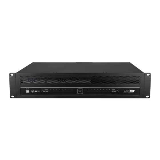
- Page 7 MU 7100EN FRONT PANEL USB (B) port for PC link. Used for system programming and administration. Input signal indicators (1 per channel). A blue LED indicates the audio signal presence in the respective channel, a red LED instead indicates a too high input signal level.
- Page 8 Are oN the lAterAl side 8 DIP-switches for MU 7100EN digital address setting. Connector with 8 control (logic) outputs. Connector with 8 control (logic) inputs that can be activated by external dry contacts. USB (A) port. Connection for USB flash drives.
- Page 9 FRONT VIEW REAR VIEW It turns 8 Ω outputs of MU 7100EN into 50 – 70 – 100 V constant voltage lines for loudspeakers with transformers. Output power alternatives: 8 x 80W, 4 x 160 W and 2 x 320W or any combination from these.
- Page 10 BM 7608D PAGING CONSOLE In addition to the BM 7608 features: Backlit LCD Numeric keyboard Menu based user interface BM 7624D PAGING CONSOLE Same features of BM 7608D paging console, but with 24 zone / function buttons. BM 7608DFM FIREMAN’S PAGING CONSOLE Same features of BM 7608D paging console, but with a high quality handheld microphone.
- Page 11 RO 7102 – DRY OUTPUT CONTACT BOARD FOR MU 7100EN A RO 7102 board can be directly connected to a pair of MU 7100EN control outputs. It converts the 2 MU 7100EN open-collector ‘control outputs’ to 2 dry closing contacts that can be used as commands for external devices.
- Page 12 MU 7100EN OPERATION AND USE MU 7100EN INTERNAL BLOCK DIAGRAM ANALOG AUDIO INPUT CARD 7 MIC/LINE IN 7 CH INPUT 8 CH 8 PCS 8 CH OUTPUT DIGITAL IMPEDANCE 8 CH COMPR./ HIGH 7x8 MATRIX MIXER POWER BASS METERING LIMITER...
- Page 13 ANALOGUE AUDIO INPUTS +48 V PHANTOM INPUT GAIN PARAMETRIC EQUALIZER (PEQ) BAND 1 BAND 2 BAND 3 MIC/LINE IN 1 +48 V PHANTOM INPUT GAIN PARAMETRIC EQUALIZER (PEQ) MIC/LINE IN 2 BAND 1 BAND 2 BAND 3 +48 V PHANTOM INPUT GAIN PARAMETRIC EQUALIZER (PEQ)
- Page 14 A higher priority of the locAl bus pAgiNg ANd iNput is muted duriNg A higher priority of the system bus pAgiNg ROUTING AND AMPLIFIER OUTPUTS MU 7100EN includes 8 digital amplifiers and digital signal processing for each output channel. LOW/HIGH PASS FILTER TONE...
- Page 15 EXAMPLE OF CONNECTION MU 7100EN < > LT 7208EN FOR 160 – 320 W LINES: LT 7208 50 / 70 / 100 V 160 W 80 W 80 W 320 W SYSTEM AND LOCAL BUS ‘System bus’ is a control bus covering the whole system. The systems components are monitored through this bus.
- Page 16 UNIT DIGITAL ADDRESS Each MU 7100EN has an individual digital address that is set through the first 7 of the 8 DIP-switches located at the rear panel. Each digital address must be set before powering the system. Two or more devices cannot have the same digital address.
- Page 17 A USB cable to link the ‘master’ MU 7100EN unit to a PC is included. INTERNAL USB (A) PORT Inside the MU 7100EN main unit, there is a USB port that is an alternative to the external USB (A) port. For instance, alarm messages (WAV files) can be stored to a USB flash drive connected to the internal USB port.
- Page 18 CONNECTORS AUDIO INPUTS 1 ÷ 7 Removable 3-pin terminal block connector 3.5mm. Max. wire section: 0.75 mm². Pins: ground, + hot, – cold SYSTEM AND LOCAL BUS OVERRIDE AUDIO OUTPUTS 1 2 3 4 5 6 RJ-11 connector Pins: 1 ground, 2 audio (+ hot), 3 audio (– cold), 4-5 relay contact LT 7208 control RJ-45 connector 1 2 3 4 5 6 7 8...
- Page 19 24 V dc power output for LT 7208EN Removable 2-pin screw terminal strip. Pins (left to right): 2 – MU 7100EN 48 V dc (redundant) power input (max. 2 x 7 A) Removable 4-pin screw terminal strip. Pins (left to right): 1 + (1st pair) 2 –...
- Page 20 System event log. System error log. SYSTEM FUNCTIONS The system is expandable by linking up to 64 MU 7100EN units via the system bus. Unique selectable address for each MU 7100EN. Up to 512 loudspeaker lines and paging zones. SYSTEM MONITORING Equipment and system monitoring according to the EN54-16 and EN 60849 standards.
- Page 21 MU 7100EN SPECIFICATIONS Analogue input 1÷7 sensitivity – 45 ÷ + 6 dBu Analogue input impedance 20 kΩ (balanced) System and local bus audio (balanced) + 6 dBu Digital message signal format (WAV) 16 bit, sampling freq.:32 / 44.1 kHz Frequency response (–...
-
Page 23: Table Of Contents
INDICE ITALIANO AVVERTENZE PER LA SICUREZZA DESCRIZIONE DEL SISTEMA MU 7100EN - PANNELLO FRONTALE MU 7100EN – PANNELLO POSTERIORE ALTRI COMPONENTI DEL SISTEMA MU 7100 – FUNZIONAMENTO ED USO CONFIGURAZIONE DEL SISTEMA CONNETTORI CARATTERISTICHE FUNZIONALI MU 7100EN - DATI TECNICI... -
Page 24: Avvertenze Per La Sicurezza
L’installazione e l’utilizzo errati del prodotto esimono la RCF S.p.A. da ogni responsabilità. ATTENZIONE: Per prevenire i rischi di fiamme o scosse elettriche, non esporre mai questo ATTENZIONE prodotto alla pioggia o all’umidità. - Page 25 Verificare inoltre l’idoneità del supporto (parete, soffitto, struttura ecc., al quale è ancorato il prodotto) e dei componenti utilizzati per il fissaggio (tasselli, viti, staffe non fornite da RCF ecc.) che devono garantire la sicurezza dell’impianto / installazione nel tempo, anche considerando, ad esempio, vibrazioni meccaniche normalmente generate da un trasduttore.
-
Page 26: Descrizione Del Sistema
Le applicazioni tipiche sono: saloni, scuole, centri commerciali, ospedali, stazioni ferroviarie, hotel, ecc. . Fino a 64 MU 7100EN c possono essere collegati insieme in modo da ottenere un sistema espanso fino a 512 zone / linee altoparlanti ed avente molte basi microfoniche. -
Page 27: Mu 7100En - Pannello Frontale
MU 7100EN - PANNELLO FRONTALE Porta USB(B) per la connessione di un computer (PC), utilizzabile per la programmazione e l’amministrazione del sistema. Indicatori dei segnali d’ingresso (1 per canale). Il LED blu indica la presenza del segnale audio, il LED rosso indica che il livello del segnale è troppo alto. -
Page 28: Mu 7100En - Pannello Posteriore
MU 7100EN – PANNELLO POSTERIORE LT 7208 16 17 18 19 Connettore per il cavo d’alimentazione da rete (da collegarsi solo ad una presa con messa a terra). Fusibili: 2 x T3.15A (5x20mm). Utilizzare sempre e solo fusibili corretti. Prima di sostituire un fusibile, il cavo d’alimentazione deve essere rimosso dalla presa elettrica. -
Page 29: Altri Componenti Del Sistema
Connettore “Local Bus” (per il collegamento di componenti del sistema DXT 7000EN). Connettore “System Bus” (per il collegamento di componenti del sistema DXT 7000EN); può inoltre essere usato per la connessione di più unità centrali MU 7100EN. Connettore “Link”: secondo connettore “System Bus” (utilizzabile per i collegamenti in cascata). - Page 30 BM 7608 – BASE MICROFONICA Base microfonica con controllo del segnale 8 tasti per selezione zone / altre funzioni Ingresso audio (jack 3.5 mm TRS) per sorgente sonora esterna Collegamento al sistema tramite cavo CAT5/ CAT6 (“System Bus” o “Local Bus”) Fino a 32 basi mic.
- Page 31 La scheda RO 7102 può essere collegata direttamente ad un paio di uscite logiche (“control output”) dell’unità centrale MU 7100EN. Sono previsti 2 contatti “puliti” normalmente aperti (2 relè, ciascuno controllato da un’uscita logica dell’unità centrale MU 7100EN) che possono essere usati come comandi per altri apparecchi.
-
Page 32: Mu 7100 - Funzionamento Ed Uso
MU 7100 – FUNZIONAMENTO ED USO MU 7100 – SCHEMA A BLOCCHI INTERNO ANALOG AUDIO INPUT CARD 7 MIC/LINE IN 7 CH INPUT 8 CH 8 PCS 8 CH OUTPUT DIGITAL IMPEDANCE 8 CH COMPR./ HIGH 7x8 MATRIX MIXER POWER BASS METERING LIMITER... - Page 33 INGRESSI AUDIO ANALOGICI +48 V PHANTOM INPUT GAIN PARAMETRIC EQUALIZER (PEQ) BAND 1 BAND 2 BAND 3 MIC/LINE IN 1 +48 V PHANTOM INPUT GAIN PARAMETRIC EQUALIZER (PEQ) MIC/LINE IN 2 BAND 1 BAND 2 BAND 3 +48 V PHANTOM INPUT GAIN PARAMETRIC EQUALIZER (PEQ)
- Page 34 ”. è disAttiVAto quANdo è iN corso uN ANNuNcio prioritArio dAl ystem MATRICE ED USCITE AUDIO AMPLIFICATE L’unità MU 7100EN include un amplificatore e l’elaborazione digitale del segnale per ciascuno degli 8 canali. LOW/HIGH PASS FILTER TONE PARAMETRIC EQUALIZER (PEQ)
- Page 35 ESEMPIO DI COLLEGAMENTO TRA MU 7100EN E LT 7208EN PER USCITE CON POTENZA 160 E 320 W: LT 7208 50 / 70 / 100 V 160 W 80 W 80 W 320 W BUS DI SISTEMA (“SYSTEM BUS”) E LOCALE (“LOCAL BUS”) Il “System Bus”...
- Page 36 INDIRIZZO DIGITALE DELL’UNITÀ Ciascuna unità centrale MU 7100EN ha un suo unico indirizzo digitale impostabile tramite i primi 7 (su 8) microinterruttori (dip-switch) posti sul pannello posteriore. Ogni indirizzo digitale deve essere impostato prima di accendere il sistema; non vi possono essere 2 o più...
-
Page 37: Configurazione Del Sistema
Riferirsi al manuale d’uso del software per PC per quanto riguarda la configurazione del sistema. Collegamento al PC: Collegare un cavo USB alla relativa porta frontale dell’unità MU 7100EN è l’altro capo ad una porta USB disponibile del PC. Accendere il sistema ed aspettare la fine della fase d’avvio. -
Page 38: Connettori
CONNETTORI INGRESSI AUDIO 1 ÷ 7 Connettore a 3 poli rimovibile (3,5mm); max. sezione dei conduttori: 0,75 mm². Poli: massa, + segnale audio (+), – segnale audio (–) USCITE AUDIO “OVERRIDE” (con contatto) “SYSTEM BUS” E “LOCAL BUS” 1 2 3 4 5 6 Connettore RJ-11 Poli: 1 massa, 2 audio (+), 3 audio (–), 4-5 contatti del relè... - Page 39 Connettore rimovibile a 2 poli. Poli (da sinistra a destra): 2 – DOPPIO INGRESSO ALIMENTAZIONE 48 V C.C. PER MU 7100EN (MAX. 2 X 7 A) Connettore rimovibile a 4 poli. Poli (da sinistra a destra): 1 + (1ª coppia) 2 –...
-
Page 40: Caratteristiche Funzionali
MONITORAGGIO DEL SISTEMA Componenti e monitoraggio del sistema secondo le norme EN54-16 e EN 60849. Controllo automatico del sistema da parte della seconda unità MU 7100EN nel caso che la prima (“master”) sia guasta. Inserimento amplificatore esterno di riserva. -
Page 41: Mu 7100En - Dati Tecnici
MU 7100EN – DATI TECNICI Sensibilità ingressi analogici 1÷7 – 45 ÷ + 6 dBu Impedenza ingressi analogici 20 kΩ (bilanciato) “System Bus” e “Local Bus” audio (bilanciato) + 6 dBu Formato segnale digitale per messaggi (WAV) ris. 16 bit, freq. Camp. 32 / 44,1 kHz Risposta in frequenza (–... - Page 44 Except possible errors and omissions. RCF S.p.A. reserves the right to make modifications without prior notice. Salvo eventuali errori ed omissioni. RCF S.p.A. si riserva il diritto di apportare modifiche senza preavviso. HEADQUARTERS: RCF S.p.A. Italy tel. +39 0522 274 411 e-mail: info@rcf.it...
Need help?
Do you have a question about the MU 7100EN and is the answer not in the manual?
Questions and answers