Table of Contents
Advertisement
Quick Links
Advertisement
Table of Contents

Subscribe to Our Youtube Channel
Related Manuals for Datavideo PTC-200


Summary of Contents for Datavideo PTC-200
- Page 1 4K PTZ CAMERA PTC-200 Instruction Manual...
-
Page 2: Table Of Contents
Table of Contents FCC COMPLIANCE STATEMENT ..............4 WARNINGS AND PRECAUTIONS ..............4 WARRANTY ....................5 ..................5 TANDARD ARRANTY ..................5 HREE ARRANTY DISPOSAL ...................... 6 PRODUCT OVERVIEW ................7 FEATURES ..................... 7 LOCATION AND FUNCTION OF PARTS ........... 8 REMOTE CONTROL AND ON-SCREEN MENU .......... - Page 3 Datavideo Technologies will try to give correct, complete and suitable information. However, Datavideo Technologies cannot exclude that some information in this manual, from time to time, may not be correct or may be incomplete. This manual may contain typing errors, omissions or incorrect information.
-
Page 4: Fcc Compliance Statement
AC adapter. If you are not sure of the type of power available, consult your Datavideo dealer or your local power company. Do not allow anything to rest on the power cord. Do not locate this unit where the power cord will be walked on, rolled over, or otherwise stressed. -
Page 5: Warranty
Drive, Solid State Drive, SD Card, USB Thumb Drive, Lighting, Camera module, PCIe Card are covered for 1 year. • The three-year warranty must be registered on Datavideo's official website or with your local Datavideo office or one of its authorized distributors within 30 days of purchase. -
Page 6: Disposal
Disposal For EU Customers only - WEEE Marking This symbol on the product or on its packaging indicates that this product must not be disposed of with your other household waste. Instead, it is your responsibility to dispose of your waste equipment by handing it over to a designated collection point for the recycling of waste electrical and electronic equipment. -
Page 7: Product Overview
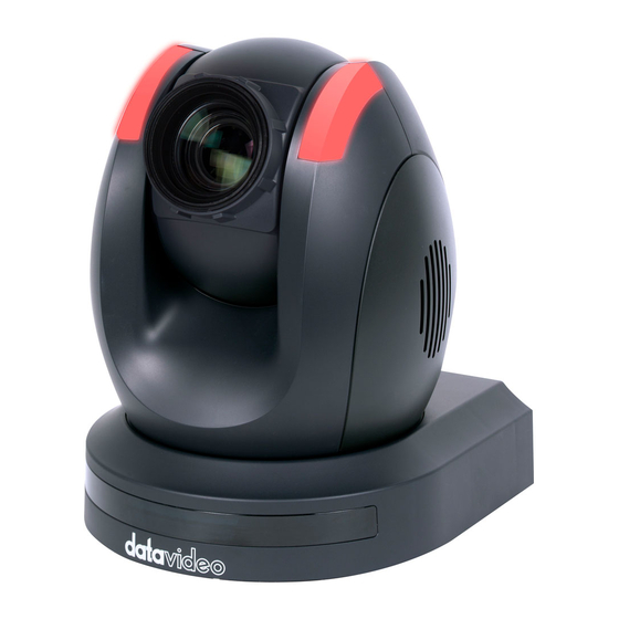
1. Product Overview The PTC-200 Video Camera is a 4K UHD PTZ camera that can be mounted on a wall, ceiling, floor, or a tabletop. The camera captures up to 4K (3,840 x 2,160, UHD) video at 2160p29.97/25 resolution, and features wide dynamic range with backlight compensation. -
Page 8: Location And Function Of Parts
3. Location and Function of Parts Front of Camera Lens Built-in 1/2.3” 8.93M Pixel CMOS HD color camera with white balance control, backlight compensation settings, automatic gain settings and etc. Tally LED Tally lamp lights up when tally signal has been transmitted to the tally signal box. -
Page 9: Remote Control And On-Screen Menu
4. Remote Control and On-Screen Menu 4.1 Remote Control Functions Item Description Reset Press RESET button to return the camera lens to the front. Use the No. button & the group button to select the group scan. Group Press any of the No. buttons 1~8 and then press GROUP button. - Page 10 Focus Setup Manually focus camera lens on a subject Press either (F) FAR button or (N) NEAR button to manually focus the camera lens onto the subject. Automatically focus camera lens on a subject Press A/ FOCUS button. Camera lens will be automatically focused Auto Focus Control on the subject such that it is positioned at the center of the screen.
- Page 11 Change camera direction Press arrow buttons to change the direction of the camera head. Stop Preset Point Auto Scan mode Press any of the DIRECTION buttons. Direction Arrows Select Menu Option Press UP or DOWN button to select the menu option. Adjust P/T Speed Press UP or DOWN button to adjust the PAN/TILT Speed.
-
Page 12: On-Screen Menu
4.2 On-Screen Menu On-Screen Menu allows the user to change various camera settings such as shooting conditions and the system setup. Press [Menu] on the remote control to enter the on-screen menu as shown below. On-Screen MENU 1: Camera Set (Normal) 2: Memory 3: Video Output 4: Remote Control... - Page 13 Details of all OSD options are described in the table below. First Level Second Level Third Level Fourth Level Sub-Option Main Options Sub-Options Parameters Parameters Descriptions NAME DISPLAY SW ON/OFF LOWER LEFT 1. Camera Name UPPER LEFT POSITION LOWER RIGHT UPPER RIGHT ESCAPE 2.
- Page 14 Mode is OFF) 9 dB 12 dB 15 dB 18 dB GAIN LIMIT 21 dB 24 dB 27 dB 30 dB 33 dB ESCAPE DNR (AT AGC ON) DNR LEVEL 3D NR LEVEL (Adjusted in DNR LEVEL) ESCAPE ESCAPE 7. Escape 1.
- Page 15 4. Waiting Time 5. Next Position 6. Escape 10. Escape BY MENU 1. Selection Way BY SWITCH 1080i60 1080i50 720p60 720p50 2. Video Mode 3. Video Output 1080p60 1080p50 2160p30 2160p25 3. Pattern COLOR BAR 4. Escape 1. PAN/TILT Reverse (Configurable using RS-422, SW 2.
- Page 16 ESCAPE Camera Status ON/OFF Escape FAST P/T Acceleration MIDDLE SLOW Normal P/T Speed X2, Surveillance PAN Torque ADJ. TILT Torque ADJ. +5.4 +4.5 +3.6 +2.7 +1.8 +0.9 2. Set Motor PAN Offset ADJ. +0.0 -0.9 -1.8 -2.7 -3.6 -4.5 -5.4 +6.3 +5.4 +4.5...
- Page 17 MCTL CPU V01.00 UPDATE ALL YES/NO ESCAPE 6. Escape NAME DISPLAY SW ON/OFF UPPER LEFT LOWER RIGHT 1. Camera Name POSITION UPPER RIGHT LOWER LEFT ESCAPE 2. Mirror ATW/AWB(AUTO) AWC (ONE PUSH) MWB (MANUAL) MODE 3200K (INDOOR) 5600K (OUTDOOR) 4200K (FLUO) SMART1 (Enabled in AWB SMART ATW...
- Page 18 (Enabled when AGC Mode is OFF) 9 dB 12 dB 15 dB 18 dB 21 dB GAIN LIMIT 24 dB 27 dB 30 dB 33 dB ESCAPE DNR(AT AGC ON) DNR LEVEL 3D NR LEVEL (Adjusted in DNR LEVEL) ESCAPE FOG CORRECTION OFF/ON 7.
- Page 19 17. Digital Zoom ON/OFF 18. Low Delay ON/SET 19. Escape 7. Reset P/T/Z YES/NO 8. Escape...
-
Page 20: Instruction For Installation
5. Instruction for Installation Step 1 – DIP Switch Setting Set the Mirror option to H+V mode. Step 2 – One End of Retaining Wire Attach the retaining wire to the junction box mounted on the ceiling by screwing one end of the retaining wire into a screw hole in the junction box with a screw (not supplied) as shown in the diagram below. -
Page 21: Step 3 - Ceiling Bracket (B)
Step 3 – Ceiling Bracket (B) • Again, as illustrated in the diagram below, screw a ceiling bracket (B) into the junction box mounted on the ceiling. • Make sure the screw holes of the ceiling bracket (B) are aligned with the holes on the junction box. -
Page 22: Step 4 - Ceiling Bracket (A) And Camera
Step 4 – Ceiling Bracket (A) and Camera Follow the steps below to screw ceiling bracket (A) into the bottom of the camera using three screws. • Position the screws as shown in the diagram below. • Align the screw holes on the bottom of the camera with those in the ceiling bracket. •... -
Page 23: Step 5 - Mount Camera To Ceiling
Step 5 – Mount Camera to Ceiling... -
Page 24: Step 6 - Screw To Fix Camera
Step 6 – Screw to Fix Camera Fix the camera in place by screwing three screws into the respective screw holes as shown in the diagram below. Step 7 – Cable Connection Connect the cables to the respective connectors on the rear of the camera. -
Page 25: Dip Switch Settings
Video mode selectable by menu IRID The IRID DIP Switch can be found on the rear panel of the PTC-200 camera. This DIP switch allows the user to assign an ID number to the camera so that the user can navigate between the cameras by pressing the CAMERA SELECT buttons. -
Page 26: Dvip Control Protocol
Set DIP Switch positions 1 and 4 to ON. Plug in the power cord into the PTC-200 and connect it to a monitor via the HDMI interface. Open the main menu by pressing the menu button on the remote control and select option 4 “Remote Control.”... - Page 27 [SET DVIP] DVIP BAUDRATE: 115200 ESCAPE Connect your PC and the PTC-200 to an Ethernet router, which should automatically assign an IP to the PTC-200. On the PC, open the DVIP Configuration Tool by double clicking “DVIP_ConfigureTools.exe.” The DVIP Configuration Tool can be obtained from Datavideo local distributors.
- Page 28 PTC-200. 11. After the network setting (Static and DHCP) and the host name are configured, click the “Apply” button. 12. The user will be prompted if the setup is successful. 13. Reboot the PTC-200 to apply the new settings.
-
Page 29: Dvip Control Operation Guide
DVIP Control Operation Guide 7.2.1 Physical Layer • Control Interface: Ethernet • Communication Speed: 10/100Mbps • Control Protocol: TCP/IP 7.2.2 General Connection Information • By default, the DVIP is configured to operate in DHCP mode. The user is allowed to reconfigure it to a static IP address. - Page 30 Command Return from DVIP device Length Descriptions 1 Byte Data Length High Byte 1 Byte Data Length Low Byte 1 Byte 0x80 1 Byte 0x00 1 Byte DHCP; 0: Disable; 1: Enable 16 Bytes DHCP Host name (15 bytes max) + Null (0x00) terminated 6 Bytes MAC Address 4 Bytes...
- Page 31 Broadcast Command List – Set DHCP Mode Command Issue to DVIP device Set DHCP Mode Command 0x02 Parameter 1 DVIP MAC address [0] Parameter 2 DVIP MAC address [1] Parameter 3 DVIP MAC address [2] Parameter 4 DVIP MAC address [3] Parameter 5 DVIP MAC address [4] Parameter 6...
- Page 32 Parameter 13 0x41 Parameter 14 0x44 Parameter 15 0x52 Parameter 16 IP_Address [0] Parameter 17 IP_Address [1] Parameter 18 IP_Address [2] Parameter 19 IP_Address [3] Parameter 20 Gateway [0] Parameter 21 Gateway [1] Parameter 22 Gateway [2] Parameter 23 Gateway [3] Command Return from DVIP device Length Descriptions...
- Page 33 Broadcast Command List – Get Device Model Number Command Issue to DVIP device Get Device Model Number Command 0x05 Parameter 1 DVIP MAC address [0] Parameter 2 DVIP MAC address [1] Parameter 3 DVIP MAC address [2] Parameter 4 DVIP MAC address [3] Parameter 5 DVIP MAC address [4] Parameter 6...
- Page 34 UDP Command List – Request TCP/IP information Command Issue to DVIP device Request TCP/IP information, include DHCP mode, DHCP Host name, IP address, Netmask, MAC address, Gateway, Primary DNS, Secondary DNS Command 0x00 Parameter 1 0x45 Parameter 2 0x54 Parameter 3 0x48 Parameter 4 0x5F...
- Page 35 1 Byte 0x01 1 Byte Firmware Revision Major Number 1 Byte Firmware Revision Minor Number UDP Command List – Set DHCP Mode Command Issue to DVIP device Set DHCP Mode Command 0x02 Parameter 1 0x53 Parameter 2 0x45 Parameter 3 0x54 Parameter 4 0x5F...
- Page 36 Parameter 15 Gateway [1] Parameter 16 Gateway [2] Parameter 17 Gateway [3] Command Return from DVIP device Length Descriptions 1 Byte 0x00 (Data Length High Byte) 1 Byte 0x05 (Data Length Low Byte) 1 Byte 0x81 1 Byte 0x03 1 Byte 0x06 (ACK) or 0x15 (NACK) UDP Command List –...
- Page 37 Parameter Null (0x00) terminated Command Return from DVIP device Length Descriptions 1 Byte 0x00 (Data Length High Byte) 1 Byte 0x05 (Data Length Low Byte) 1 Byte 0x81 1 Byte 0x09 1 Byte 0x06 (ACK) or 0x15 (NACK) UDP Command List – Set Netmask Command Issue to DVIP device Set Netmask Command...
- Page 38 Parameter 6 0x41 Parameter 7 0x54 Parameter 8 0x45 Parameter 9 0x57 Parameter 10 0x41 Parameter 11 0x59 Parameter 12 Gateway [0] Parameter 13 Gateway [1] Parameter 14 Gateway [2] Parameter 15 Gateway [3] Command Return from DVIP device Length Descriptions 1 Byte 0x00 (Data Length High Byte)
- Page 39 UDP Command List – Set Secondary DNS Address Command Issue to DVIP device Set Gateway Address Command 0x0E Parameter 1 0x53 Parameter 2 0x45 Parameter 3 0x54 Parameter 4 0x5F Parameter 5 0x53 Parameter 6 0x45 Parameter 7 0x43 Parameter 8 0x44 Parameter 9 0x4E...
- Page 40 Command Return from DVIP device Length Descriptions 1 Byte 0x00 (Data Length High Byte) 1 Byte 0x05 (Data Length Low Byte) 1 Byte 0x81 1 Byte 0x0F 1 Byte 0x06 (ACK) or 0x15 (NACK)
-
Page 41: Rs-422 Control Protocol
In VISCA, the side outputting commands, for example, a computer is called the controller, while the side receiving the commands, such as a PTC-200, is called the peripheral device. The PTC-200 serves as a peripheral device in VISCA. In VISCA, up to seven peripheral devices like the BRC- 300/P can be connected to one controller using communication conforming to the RS-232C/RS- 422 standard. -
Page 42: Visca Communication Specifications
81H. The packet sent to the PTC-200 assigned address 2 is 82H. In the command list, as the header is 8X, input the address of the PTC-200 at X. The header of the reply packet from the PTC-200 assigned address 1 is 90H. The packet from the PTC-200 assigned address 2 is A0H. - Page 43 ACK or an error message, for query commands, an Inquiry Packet) to be carried out before sending the next one. 8.2.2.3 Command and inquiry • Command Sends operational commands to the PTC-200. • Inquiry Used for inquiring about the current state of the PTC-200.
-
Page 44: Visca Device Setting Command
8.2.2.4 Responses for commands and inquiries • ACK message Returned by the PTC-200 when it receives a command. No ACK message is returned for inquiries. • Completion message Returned by the PTC-200 when execution of commands or inquiries is completed. In the case of inquiry commands, it will contain reply data for the inquiry after the 3 byte of the packet. -
Page 45: Visca Command/Ack Protocol
8.2.3.1 VISCA interface command • IF_Clear Clears the command buffers in the PTC-200 and cancels the command currently being executed. Command Packet Reply Packet Note IF_Clear 8X 01 00 01 FF X0 50 FF IF_Clear (broadcast) 88 01 00 01 FF... -
Page 46: Visca Camera-Issued Messages
(y: Socket No.) executed due to current conditions. For example, when commands controlling the focus manually are received during auto focus. 8.2.6 PTC-200 Commands 8.2.6.1 PTC-200 Command List Command Set Command Command Packet Comments AddressSet Broadcast 88 30 01 FF... - Page 47 Direct 8x 01 04 48 0p 0q 0r 0s FF pqrs: Focus Position* Auto Focus 8x 01 04 38 02 FF AF ON/OFF Manual Focus 8x 01 04 38 03 FF One Push 8x 01 04 18 01 FF One Push AF Trigger Trigger CAM_WB...
- Page 48 Direct 8x 01 04 4C 00 00 0p 0q FF pq: Iris Position* CAM_Backlight 8x 01 04 33 02 FF Back Light ON/OFF 8x 01 04 33 03 FF PTZ_Position Reset 8x 01 04 3F 00 0p FF Memory Number p (=0 to 50) 8x 01 04 3F 01 0p FF Memory Number p...
- Page 49 8.2.6.2 PTC-200 Inquiry Command List Inquiry Command Command Inquiry Packet Comments Packet CAM_PowerInq 8x 09 04 00 FF y0 50 02 FF y0 50 03 FF Off (Standby) CAM_ZoomPosInq 8x 09 04 47 FF y0 50 0p 0q 0r 0s FF...
-
Page 50: Firmware Update
9. Firmware Update Copy two image files, p200mcpu.bin and p200mctl.bin, into the root directory of a USB hard drive (<16 GB) and insert it into the USB port of the PTC-200 (You may also use USB extension cord). Open the operation menu using the IR remote controller (select from CAM 1-4; default is... -
Page 51: Dimensions
10. Dimensions Unit: mm... -
Page 52: Specifications
11. Specifications Video Image Pickup Element 1/2.3” type Exmor R CMOS Effective Picture Elements Approx. 8.93 Mega pixels Resolution HD / FHD / UHD 4K (3,840 x 2,160, UHD): 2160p/29.97, 2160p/25 Signal System 1080p/59.94, 1080p/50, 1080i/59.94, 1080i/50, 720p/59.94, 720p/50 50%, High Sensitivity Mode: Color: 0.75 lx (F1.8, AGC on, 1/30s) Min. - Page 53 Lens Lens Type 12x Optical Zoom F = 3.9 mm (WIDE) to 46.8 mm (TELE) Focal Length F1.8 to F2.0 Angle of View (Horizontal) Approx. 70.7 degrees (WIDE END) / 6.4 degrees (TELE END) Video Output HDMI (V1.4) x 1 Video Output 3G-SDI x 1 Control...
-
Page 54: Service & Support
Service & Support It is our goal to make owning and using Datavideo products a satisfying experience. Our support staff is available to assist you to set up and operate your system. Contact your local office for specific support requests. Plus, DATAVIDEO WORLDWIDE OFFICES please visit www.datavideo.com to access our FAQ section.
Need help?
Do you have a question about the PTC-200 and is the answer not in the manual?
Questions and answers