Table of Contents
Advertisement
Quick Links
Advertisement
Table of Contents

Related Manuals for Datavideo ptc-200


Summary of Contents for Datavideo ptc-200
- Page 1 4K PTZ CAMERA PTC-200 Instruction Manual...
-
Page 2: Table Of Contents
Table of Contents FCC Compliance Statement Warnings and Precautions Warranty Standard Warranty Three Year Warranty Disposal Product Overview Features Camera Functions DIP Switch Settings DIP Switch SW1 DIP Switch SW2 (IRID) IR Remote Control Remote Control Functions On-Screen Menu Instruction for Installation Step 1 –... - Page 3 Disclaimer of Product and Services The information offered in this instruction manual is intended as a guide only. At all times, Datavideo Technologies will try to give correct, complete and suitable information. However, Datavideo Technologies cannot exclude that some information in this manual, from time to time, may not be correct or may be incomplete.
-
Page 4: Fcc Compliance Statement
7. This product should only be operated from the type of power source indicated on the marking label of the AC adapter. If you are not sure of the type of power available, consult your Datavideo dealer or your local power company. -
Page 5: Warranty
Warranty Standard Warranty • Datavideo equipment are guaranteed against any manufacturing defects for one year from the date of purchase. • The original purchase invoice or other documentary evidence should be supplied at the time of any request for repair under warranty. -
Page 6: Three Year Warranty
Camera module, PCIe Card are covered for 1 year. • The three-year warranty must be registered on Datavideo's official website or with your local Datavideo office or one of its authorized distributors within 30 days of purchase. Disposal For EU Customers only - WEEE Marking... -
Page 7: Product Overview
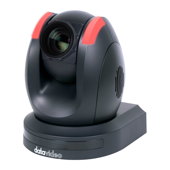
Product Overview The PTC-200 Video Camera is a 4K UHD PTZ camera that can be mounted on a wall, ceiling, floor, or a tabletop. The camera captures up to 4K (3,840 x 2,160, UHD) video at 2160p29.97/25 resolution, and features a wide dynamic range with backlight compensation. -
Page 8: Camera Functions
Camera Functions Front of Camera Lens Built-in 1/2.3” 8.93M Pixel CMOS HD color camera with white balance control, backlight compensation settings, automatic gain settings and etc. Tally LED Tally lamp lights up when tally signal has been transmitted to the tally signal box. - Page 9 DVIP Communication Port This port is used to connect the camera directly to the PC or to a network router via any RJ-45 cables. Section 7 for configuring the camera’s network settings using the DVIP Network Configuration Tool. Power Input DC in socket connects the supplied 12V PSU.
-
Page 10: Dip Switch Settings
DIP Switch Settings DIP Switch SW1 The DIP Switch SW1 can be found at the bottom of the camera, where the user is allowed to set the camera’s VISCA ID, enable remote control, select the video resolution, and configure how the video mode can be selected. DIP SW 1/2/3 VISCA ID ON/OFF/OFF... -
Page 11: Dip Switch Sw2 (Irid)
DIP Switch SW2 (IRID) The IRID DIP Switch can be found on the rear panel of the PTC-200 camera. This DIP switch allows the user to assign an ID number to the camera so that the user can navigate between the cameras by pressing the CAMERA SELECT buttons. -
Page 12: Ir Remote Control
IR Remote Control Remote Control Functions Item Description Reset Press RESET button to return the camera lens to the front. Use the No. button & the group button to select the group scan. Group Press any of the No. buttons 1~8 and then press GROUP button. - Page 13 Focus Setup Manually focus camera lens on a subject Press either (F) FAR button or (N) NEAR button to manually focus the camera lens onto the subject. Automatically focus camera lens on a subject Press A/ FOCUS button. Camera lens will be automatically focused Auto Focus Control on the subject such that it is positioned at the center of the screen.
- Page 14 Change camera direction Press arrow buttons to change the direction of the camera head. Stop Preset Point Auto Scan mode Press any of the DIRECTION buttons. Direction Arrows Select Menu Option Press UP or DOWN button to select the menu option. Adjust P/T Speed Press UP or DOWN button to adjust the PAN/TILT Speed.
-
Page 15: On-Screen Menu
On-Screen Menu On-Screen Menu allows the user to change various camera settings such as shooting conditions and the system setup. Press [Menu] on the remote control to enter the on-screen menu as shown below. On-Screen MENU 1: Camera Set (Normal) 2: Memory 3: Video Output 4: Remote Control... - Page 16 Details of all OSD options are described in the table below. First Level Second Level Third Level Fourth Level Sub-Option Main Options Sub-Options Parameters Parameters Descriptions NAME DISPLAY SW ON/OFF LOWER LEFT 1. Camera UPPER LEFT Name POSITION LOWER RIGHT UPPER RIGHT ESCAPE 2.
- Page 17 CLOSE ESCAPE AGC MODE MANUAL GAIN (Enabled when 0 dB ~ GAIN LIMIT AGC Mode is OFF) 9 dB 12 dB 15 dB DAY (COLOR) AGC 18 dB GAIN LIMIT 21 dB 24 dB 27 dB 30 dB 33 dB ESCAPE 6.
- Page 18 1/300 1/425 1/600 1/1000 1/1250 6. WB Mode 7. WB R-Gain 0-127 8. WB B-Gain 0-127 9. Escape 51. Escape 1. Preset No. 2. Item ON/OFF ----/OF_SPD--_W- 3. Speed Limit Group-1-8 --_NEXT 4. Waiting Time 5. Next Position 6. Escape 10.
- Page 19 ESCAPE (Configurable IR GROUP ID CAM1~4 using DIP switch 5. Set IR bit 9/10 ONLY) ESCAPE 6. PTZ INFO. ON/OFF Output 7. Escape PAN OSD ON/OFF TILT OSD ON/OFF PTZ OSD ZOOM OSD ON/OFF ESCAPE DEBUG IR OSD ON/OFF DEBUG CAM. OSD ON/OFF DEBUG RS-422 ON/OFF...
- Page 20 -0.9 -1.8 -2.7 -3.6 -4.5 -5.4 +6.3 +5.4 +4.5 +3.6 +2.7 +1.8 +0.9 Tilt Offset ADJ. +0.0 -0.9 -1.8 -2.7 -3.6 -4.5 -5.4 -6.3 Escape RED/GREEN GREEN 3. Tally Light 4. Reset All YES/NO SW VERSION ESCAPE MB CPU V00.28a 5.
- Page 21 SMART1 (Enabled in AWB SMART ATW SMART2 (AUTO) mode) SMART3 (Enabled when MWB RED 0~128~255 MODE is set to COMPONENT MWB (MANUAL)) (Enabled when MWB BLUE 0~128~255 MODE is set to COMPONENT MWB (MANUAL)) ESCAPE AUTO FOCUS MODE MANUAL AF SENSITIVITY 4.
- Page 22 3D NR LEVEL (Adjusted in DNR LEVEL) ESCAPE 7. Fog FOG CORRECTION OFF/ON Correction ESCAPE 8. Aperture 0~15 9. Color Gain 0~14 10. Exposure 0~14 Comp. (This option is 11. Backlight OFF/ON enabled after AGC Correction is turned on) 12. Day/Night Mode COLOR 1/30...
-
Page 23: Instruction For Installation
Instruction for Installation Step 1 – DIP Switch Setting Set the Mirror option to H+V mode. Step 2 – One End of Retaining Wire Attach the retaining wire to the junction box mounted on the ceiling by screwing one end of the retaining wire into a screw hole in the junction box with a screw (not supplied) as shown in the diagram below. -
Page 24: Step 3 - Ceiling Bracket (B)
Step 3 – Ceiling Bracket (B) • Again, as illustrated in the diagram below, screw a ceiling bracket (B) into the junction box mounted on the ceiling. • Make sure the screw holes of the ceiling bracket (B) are aligned with the holes on the junction box. -
Page 25: Step 4 - Ceiling Bracket (A) And Camera
Step 4 – Ceiling Bracket (A) and Camera Follow the steps below to screw ceiling bracket (A) into the bottom of the camera using three screws. • Position the screws as shown in the diagram below. • Align the screw holes on the bottom of the camera with those in the ceiling bracket. -
Page 26: Step 5 - Mount Camera To Ceiling
Step 5 – Mount Camera to Ceiling... -
Page 27: Step 6 - Screw To Fix Camera
Step 6 – Screw to Fix Camera Fix the camera in place by screwing three screws into the respective screw holes as shown in the diagram below. Step 7 – Cable Connection Connect the cables to the respective connectors on the rear of the camera. -
Page 28: Network Configuration
Note: All devices should be connected to the same network domain. 1. First connect the DVIP port of the PTC-200 PTZ camera to a Windows computer using an RJ-45 Ethernet cable. Note: You do not need to manually assign an IP address to the PC but make sure the right interface card is selected at Step 11. - Page 29 10. On the PC, open the DVIP Configuration Tool by double clicking “DVIP_Net_Conf.exe.” The DVIP Configuration Tool can be obtained from Datavideo local distributors or downloaded from the product page. 11. After the DVIP Configuration Tool is opened, select your network interface card and click the “OK”...
- Page 30 12. On the DVIP Device List, you will then be able to see the Device Name, MAC address and IP address of the connected device. 13. After the network setting (Static or DHCP) and the host name are properly configured, click the “Save” button to write the new information into the device.
- Page 31 15. Reboot the device to apply the new settings. In addition to configuring network settings of the connected DVIP devices, the DVIP configuration tool also allows you to search for DVIP devices, clear the device list, switch to other interface cards and change the interface language. Each individual function is described below.
- Page 32 • Switch to Other Network Interfaces To select other network interface cards, click Network Network Card • Language Selection On the tool bar, select a language: Traditional Chinese, Simplified Chinese or English...
-
Page 33: Rmc-180 Ptz Camera Control Unit
DIP switch located at the bottom to OFF. Direct Connection to Camera To use the RMC-180 PTZ Camera Control Unit to directly control the PTC-200 camera, connect the RS-422 port on the camera’s rear panel to the RJ-45 port of the RMC-180 using any RJ-45 cable. -
Page 34: Firmware Update
1) Copy two image files, p200mcpu.bin and p200mctl.bin, into the root directory of a USB hard drive (<16 GB) and insert it into the USB port of the PTC-200 (You may also use USB extension cord). 2) Open the operation menu using the IR remote controller (select from CAM 1-4;... -
Page 35: 10. Dimensions
10. Dimensions Unit: mm... -
Page 36: 11. Specifications
11. Specifications Video Image Pickup Element 1/2.3” type Exmor R CMOS Effective Picture Elements Approx. 8.93 Mega pixels Resolution HD / FHD / UHD 4K (3,840 x 2,160, UHD): 2160p/29.97, 2160p/25 Signal System 1080p/59.94, 1080p/50, 1080i/59.94, 1080i/50, 720p/59.94, 720p/50 50%, High Sensitivity Mode: Color: 0.75 lx (F1.8, AGC on, 1/30s) Min. - Page 37 Pan / Tilt / Zoom Pan/Tilt Range Pan: 270° , Tilt: +90° to -12° Manual: 1~150°/Sec Pan/Tilt Speed Swing: 1~150°/Sec Initialization Time 30 sec P, T, Z (While Panning , Tilting and Zooming ) by Coordinate Report frame Lens Lens Type 12x Optical Zoom F = 3.9 mm (WIDE) to 46.8 mm (TELE) Focal Length...
-
Page 38: Service & Support
Service & Support It is our goal to make owning and using Datavideo products a satisfying experience. Our support staff is available to assist you to set up and operate your system. Contact your local office for specific support requests. Plus, DATAVIDEO WORLDWIDE OFFICES please visit www.datavideo.com to access our FAQ section.
Need help?
Do you have a question about the ptc-200 and is the answer not in the manual?
Questions and answers