
Related Manuals for Carrier Access Access Navigator

Summary of Contents for Carrier Access Access Navigator
- Page 1 Access Navigator ANUAL Part Number: 770-0079-AP Product Release: 1.8 August 2003...
- Page 2 - electronic, mechanical, magnetic, optical, chemical, manual, or otherwise - any part of this manual or software supplied with the Access Navigator for any purpose other than the purchaser's personal use without the express written permission of Carrier Access Corporation.
-
Page 3: Table Of Contents
In this Preface Compliance ... iv Notices ... iv Electrostatic Discharge (ESD) Precautions Carrier Access Software License Agreement Warranty ... ix REFACE Preface ... v ... vi... -
Page 4: Preface
Notes should be read before performing the required action. ANGER NOTICE INDICATES THE PRESENCE OF A HAZARD THAT CAN OR WILL AUTION NOTICE INDICATES THE POSSIBILITY OF INTERRUPTING NETWORK ARNING NOTICE INDICATES THE POSSIBILITY OF EQUIPMENT DAMAGE IF August 2003 Access Navigator - Release 1.8... -
Page 5: Electrostatic Discharge (Esd) Precautions
TECHNIQUES THAT CONFORM TO ACCEPTED INDUSTRY PRACTICES The ESD warning label appears on packages and storage bags that contain static-sensitive products and components. Access Navigator - Release 1.8 NTEGRATED CIRCUITS ARE EXTREMELY SUSCEPTIBLE TO ELECTRO NLESS YOU ARE A QUALIFIED SERVICE TECHNICIAN WHO USES TOOLS AND... -
Page 6: Carrier Access Software License Agreement
THIS PACKAGE INDICATES THAT YOU HAVE ACCEPTED THESE TERMS AND CONDITIONS AND AGREE TO BE BOUND BY THEM. CARRIER ACCESS CORPORATION provides this Software and licenses its use to you, the LICENSEE, pursuant to the following terms. "LICENSEE" means the entity that has accepted the terms and conditions of this License by opening this package, references to "LICENSOR"... -
Page 7: Copyright
LIMITATION ANY LOST DATA, LOST PROFITS, AND COSTS OF PROCUREMENT OF SUBSTITUTE GOODS OR SERVICES, ARISING FROM OR RELATING TO THESE LICENSE TERMS, HOWEVER CAUSED AND UNDER ANY THEORY OF LIABILITY Access Navigator - Release 1.8 August 2003 Preface 1vii... -
Page 8: Jurisdiction And Venue
License Terms shall be brought solely in the state and federal courts of Colorado, and each Party irrevocably submits to the jurisdiction and venue of any such court in any such action or proceeding. 1viii August 2003 Access Navigator - Release 1.8... -
Page 9: Warranty
The remedies contained in this agreement will be the sole and exclusive remedies whether in contract, tort or otherwise, and Carrier Access Corporation will not be liable for injuries or damages to persons or property resulting from any case whatsoever, with the exception of injuries or damages caused by the gross negligence of Carrier Access Corporation. -
Page 10: Warranty Product Returns
Preface Warranty Product Returns Before returning any equipment to Carrier Access, first contact the distributor or dealer from which you purchased the product. A Return Material Authorization (RMA) number is required for all equipment returned to Carrier Access. Call Carrier Access Customer Support at (800) 786-9929 or (303) 442-5455 for RMA number, repair/warranty information and shipping instructions. - Page 11 System Architecture ......... . 1-4 Carrier Access Support Products ....... . 1-5 Access Banks .
- Page 12 Ordering Information ........2-12 Access Navigator / GR-303 + Data Host Overview .
- Page 13 Ordering Information ........3-16 Access Navigator / GR-303 Host with P-Phone Overview .
- Page 14 Tools and Materials ........6-5 Run Ground Wire to Access Navigator ..... . . 6-6 Connect Ground Wire to Ground Lug .
- Page 15 Verify Wiring ......... . 6-37 Connect Power Plugs to Access Navigator....6-37 Access Navigator - Release 1.8...
- Page 16 Exit Management Session ....... . 6-65 1xvi August 2003 Access Navigator - Release 1.8...
-
Page 17: Start Management Session
Obtain Information ........7-5 Connect RS-232 Cable to Access Navigator ....7-5 Set Up Terminal Program . - Page 18 Verify System Equipment Configuration ..... . . 11-11 Temporarily Disable Configuration Downloading ....11-14 1xviii August 2003 Access Navigator - Release 1.8...
- Page 19 Test DS1 and DS0 Circuits ........13-23 Access Navigator - Release 1.8...
- Page 20 Status Remote ........15-21 August 2003 Access Navigator - Release 1.8...
- Page 21 Technical Support ......... 15-54 Access Navigator - Release 1.8...
- Page 22 Download Software ........17-20 1xxii August 2003 Access Navigator - Release 1.8...
- Page 23 Clear TMC Log ........18-28 Access Navigator - Release 1.8...
- Page 24 Send Remote RS232 Line Loopup ......18-81 Send Remote RS232 TSI Loopup ......18-82 1xxiv August 2003 Access Navigator - Release 1.8...
- Page 25 Set Remote RS232 Stop ....... . 18-120 Access Navigator - Release 1.8...
- Page 26 Show TMC ......... 18-153 1xxvi August 2003 Access Navigator - Release 1.8...
- Page 27 Notifications..........A-18 Access Navigator - Release 1.8...
- Page 28 Overview ..........C-2 Carrier Access Enterprise MIB ....... . . C-3 SNMP Basics.
-
Page 29: In This Chapter
In this Chapter Overview ... 1-2 Features and Benefits Access Navigator Configurations System Architecture Carrier Access Support Products Management ... 1-6 HAPTER Introduction ... 1-3 ... 1-3 ... 1-4 ... 1-5... -
Page 30: Overview
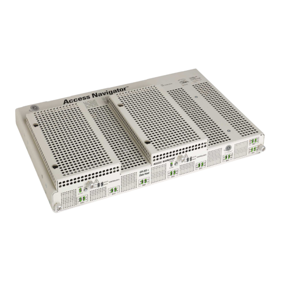
GR-303 with Data Host GR-303 Host with P-Phone The Access Navigator is a complete solution for managing 4 to 32 T1 access connections. In conjunction with Carrier Access’ remotely managed Adit® 600 and Access Bank® families of T1 voice and data access products, the Access Navigator provides an end-to-end managed solution for deploying T1-based multi-line voice and data services to businesses, with up to 24 voice lines and data rates up to 1.536 Mbps. -
Page 31: Features And Benefits
Remote management of CA’s Adit 600 terminals using IP commands via T1 DS0 channel Access Navigator Configurations With up to 32 DS1 interfaces, the Access Navigator has the capacity and flexibility to deploy a variety of voice and data services. Configurations include: Access Navigator / DCS Service Manager –... -
Page 32: System Architecture
System Architecture System Architecture The Access Navigator is a distributed system in which the Access Navigator is the host terminal located at a co-location or customer premise. CA’s Access Bank® and Adit® 600 products operate as remotely managed service units at the customer premises. -
Page 33: Carrier Access Support Products
Adit® 600 family of Customer Service Terminals (see Figure 1-2) includes: Adit 600 TDM – 6 service card slots support up to 18 T1s per unit, up to 48 voice channels, or any combination of voice and data services Access Navigator - Release 1.8 Carrier Access Support Products August 2003... -
Page 34: Management
Management Management The Access Navigator includes RS-232 and Ethernet ports for local and remote management, provisioning, and testing (see Figure 1-3). Flow-through provisioning enables the Access Navigator to pre-provision, test and manage remote Access Bank II units to provide the required voice and data services. The Access Navigator also provides host support for provisioning and managing Adit 600 terminals. -
Page 35: Snmp
SNMP The Access Navigator SNMP Agent is based on the SNMPv1 standard. It implements the following two industry standard specifications for the TCP/IP and DS1 interfaces, plus an Enterprise MIB developed for managing CA’s Access Bank II products: RFC 1213 – Management Information Base for Network Management of TCP/IP-based internets: MIB-II RFC 1406 –... -
Page 36: Valet And Networkvalet Ems Software
Valet and NetworkValet send commands over the carrier’s IP network to communicate with the SNMP agent in the Access Navigator. The Access Navigator includes a standard 10Base-T Ethernet port for connection to the hub or network interface, or laptop computer. The Access Navigator must have FLASH software version 1.7 or higher to support IP DS0 management of remote Adit 600 terminals. -
Page 37: Access Navigator / Dcs Service Manager
Access Navigator / DCS Service Manager In this Chapter Overview System Architecture Features and Benefits Configuration Applications Interfaces Specifications Compliance Requirements Ordering Information ... 2-2 ... 2-3 ... 2-4 ... 2-6 ... 2-7 ... 2-7 ... 2-7 ... 2-10 ... 2-12... -
Page 38: Overview
Overview Overview The Access Navigator® / DCS Service Manager is a complete service solution for managing 4 to 32 T1 access connections. The power of a remotely managed, 32-port, Digital Crossconnect System (DCS) is contained in only 1½ rack units. Integrated testing and optional common equipment redundancy ensure carrier-class service availability. -
Page 39: System Architecture
Voice Public Network DCS Voice and Data Internet, Data, Private and Special Services Data Network Switch Center Figure 2-2. Access Navigator / DCS Service Manager Architecture Access Navigator - Release 1.8 Remote Management Voice Ethernet RS-232 Telnet & SNMP Access Bank I... -
Page 40: Features And Benefits
CSU or NIU shelves. Additional Quad T1 Framer cards can be installed while the Access Navigator is in service to provide from 4 to 32 DS1/CSU connection ports. TFTP and Xmodem utilities permit software updates to redundant systems without affecting service. - Page 41 TCP/IP Network Access Navigator Element Manager Voice Switch Data Switch Figure 2-3. Access Navigator Management Architecture Access Navigator - Release 1.8 Access Navigator / DCS Service Manager On-Net Customer Location Wiring Closet ACCESS BANK II Span 1 Span 2 T1 Test 1 T1 Test 2 V.
-
Page 42: Configuration
Access Navigator / DCS Service Manager Configuration Configuration Hardware configuration: Modular construction with plug-in cards includes built-in circuit and network testing and fuse-less protection (see Figure 2-4). Software configuration: Operating system is stored in upgradeable flash memory. Configuration and provisioning data are stored in nonvolatile RAM, protected from power interruptions. -
Page 43: Applications
Framing: D4 (SF) or ESF DS1 receive sensitivity: –28dB to +1.5dB Line build-outs: DSX-1 (0 to 660 ft. in 5 steps) CSU (0 dB, –7.5 dB, –15 dB, –22.5dB) Access Navigator - Release 1.8 Access Navigator / DCS Service Manager August 2003 Applications... -
Page 44: System Clocking
Access Navigator / DCS Service Manager System Clocking ANSI T1.403, Section 6 & 7 (jitter, pulse mask transmission, receive sensitivity, framing formats) Built-in CSU with loopback and BERT for testing the T1s System Clocking Primary and secondary sources from: DS1s, external clock source (such as BITS) or internal... -
Page 45: Compliance
No fans; Passive thermal management Physical Dimensions: 17" x 13.5" x 2.63" Weight: 10 lbs. (4.54 kg) Mounts in 19 and 23 inch racks Optional wall mount brackets Access Navigator - Release 1.8 Access Navigator / DCS Service Manager August 2003 Compliance... -
Page 46: Compliance Requirements
Access Navigator / DCS Service Manager Compliance Requirements Compliance Requirements FCC Requirements This equipment complies with Part 15 and Part 68 of the Federal Communications Commission (FCC) Rules. Part 15, Class A This equipment has been tested and found to comply with the limits for a Class A digital device in accordance with Part 15 of the FCC Rules. -
Page 47: Telcordia (Bellcore) Requirements
If you need to make repairs or modifications to the equipment, please first contact Carrier Access Corporation for repair, modification, and warranty information. Customer repairs and modifications are limited to the replacement of circuit boards;... -
Page 48: Csa Requirements
AN-DCS Controller Access Navigator Controller card with Digital Card Crossconnect System (DCS) software. Quad T1 Framer Card Access Navigator Quad T1 Framer card terminates 4 T1 interfaces from switch, customer site, or data network. DSX-1 Cable 64-pin DSX-1 cable, 10 feet long, male/male. -
Page 49: Features And Benefits
Access Navigator / GR-303 + Data Host In this Chapter Overview ... 3-2 System Architecture Features and Benefits GR-303 Services DCS Services Management Architecture Configuration Applications ... 3-10 Interfaces ... 3-10 Specifications Compliance Requirements Ordering Information HAPTER ... 3-3 ... 3-4 ... -
Page 50: Overview
Overview Overview The Access Navigator® / GR-303 + Data Host offers a highly integrated solution for combining multi-line local voice and data services on customer T1 access lines. Using the Telcordia® standard GR-303 switching protocol, up to 672 customer telephone channels can be assigned on a call-by-call basis to Class 5 local digital switch T1 connections. -
Page 51: System Architecture
Switch with GR-303 DCS Voice and Data Internet, Data, Private and Special Services Switch Center Figure 3-2. Access Navigator / GR-303 + Data Host Architecture Access Navigator - Release 1.8 Remote A CCESS BANK I Management Self Test Normal N ormal... -
Page 52: Gr-303 Services
Features and Benefits Features and Benefits The Access Navigator / GR-303 + Data Host is a transport element that combines the functions of a GR-303 digital terminal, 32-port T1 digital crossconnect system, T1 channel/data service unit (CSU), T1 diagnostic test equipment, and Access Bank® II host controller into a modular chassis 1½ rack units high. Ethernet SNMP, optional redundancy, and modular T1 expansion provide carrier-class service protection and management at either carrier or customer located T1 service access points. - Page 53 CA's Access Navigator / GR-303 + Data Host, together with the Access Bank II and Adit 600, bring cost- effective concentration and remote management to competitive local carriers with a new level of serviceability and space efficiency. GR-303 Voice &...
-
Page 54: Dcs Services
DCS Services DCS Services The Access Navigator provides all the grooming and filling functions of a 1/0 digital crossconnect system (DCS) to maximize T1 usage. With carrier/customer demarcation testing, carriers are able to decrease maintenance costs and labor, while increasing service availability. Fractional voice and data services from multiple customers and applications are combined by the Access Navigator to save recurring backhaul transmission costs, and capital costs on switch or router ports. -
Page 55: Management Architecture
Adit 600 terminals. IP DS0 management uses a colocated Adit 600 terminal with an IP Router card to redirect IP messages between the Access Navigator’s IP port and the 24 DS0s on a groom DS1. The Access Navigator then cross-connects the groom DS0s to a dedicated drop DS0 going to each remote Adit 600. -
Page 56: Fdl Management
Access Navigator / GR-303 + Data Host FDL Management FDL Management When T1 Type I lines are available, the Access Navigator can use the ESF Faciltiy Data Link channel to manage remote Access Bank II and Adit 600 terminals. Network... -
Page 57: Configuration
GR-303 digital loop carrier (DLC) system with the functionality of a miniature 1/0 digital crossconnect switch (DCS). Providing up to 32 DS1 ports (768 DS0s) in one small package, the Access Navigator fits easily into small collocation spaces and phone closets. -
Page 58: Applications
Access Navigator / GR-303 + Data Host Applications Applications T1 Service POP-In-A-Box: Customer-located T1 access management for carriers Call Concentration: Variable concentration of voice calls for more efficient use of backhaul T1s and switch resources End-Office T1 Grooming: T1 access consolidation, provisioning, protection, and service... -
Page 59: Specifications
System Clocking Primary and secondary sources from: DS1s, external clock source (such as BITS) or internal clock (minimum Stratum 4) Automatic clock switching and holdover Access Navigator - Release 1.8 Access Navigator / GR-303 + Data Host August 2003 Specifications 3-11... -
Page 60: Gr-303 Signaling
Access Navigator / GR-303 + Data Host GR-303 Signaling GR-303 Signaling GR-303 ABCD robbed-bit signal codes GR-303 Direct Inward Dial (DID) signaling for Lucent switches GR-303 4:1 TDM mode support for ISDN BRI FXS loop start and ground start DCS Signaling... -
Page 61: Compliance
No fans; Passive thermal management Physical Dimensions: 17" x 13.5" x 2.63" Weight: 10 lbs. (4.54 kg) Mounts in 19 and 23 inch racks Optional wall mount brackets Access Navigator - Release 1.8 Access Navigator / GR-303 + Data Host August 2003 Compliance 3-13... -
Page 62: Compliance Requirements
Access Navigator / GR-303 + Data Host Compliance Requirements Compliance Requirements FCC Requirements This equipment complies with Part 15 and Part 68 of the Federal Communications Commission (FCC) Rules. Part 15, Class A This equipment has been tested and found to comply with the limits for a Class A digital device in accordance with Part 15 of the FCC Rules. -
Page 63: Telcordia (Bellcore) Requirements
If you need to make repairs or modifications to the equipment, please first contact Carrier Access Corporation for repair, modification, and warranty information. Customer repairs and modifications are limited to the replacement of circuit boards;... -
Page 64: Csa Requirements
AN-GR-303 Access Navigator Controller card with GR-303 Controller Card and DCS software. Quad T1 Framer Card Access Navigator Quad T1 Framer card terminates 4 T1 interfaces from switch, customer site, or data network. DSX-1 Cable 64-pin DSX-1 cable, 10 feet long, male/male. - Page 65 Access Navigator / GR-303 Host with In this Chapter Overview ... 4-2 System Architecture Features and Benefits GR-303 Services ... 4-4 P-Phone Services ... 4-6 DCS Services ... 4-7 Management Architecture Configuration ... 4-10 Applications ... 4-11 Interfaces ... 4-11 Specifications ...
-
Page 66: Overview
5 local digital switch T1 connections. When connected to a Nortel DMS switch providing Nortel Proprietary Phone (P-Phone) Centrex service, the Access Navigator can support up to 384 P-Phone channels from up to 14 remote Adit 600s. In addition to the concentration and management of CLASS® voice services, the Access Navigator grooms, and optionally concentrates, fractional T1 data connections from customer locations. -
Page 67: System Architecture
DCS Voice and Data Internet, Data, Private and Special Services Data Network Switch Center Figure 4-2. Access Navigator / GR-303 with P-Phone Architecture Access Navigator - Release 1.8 Access Navigator / GR-303 Host with P-Phone Remote ACCESS BANK I Management Self... -
Page 68: Features And Benefits
1½ rack units of space. Integrated testing and optional common equipment redundancy assure carrier-class service availability. CA's Access Navigator / GR-303 Host with P-Phone, together with the Access Bank II and Adit 600, bring cost-effective concentration and remote management to competitive local carriers with a new level of serviceability and space efficiency. - Page 69 ISDN BRI Data GR-303 Interface Group Switch Integrated Digital Terminal (IDT) Figure 4-3. Access Navigator / GR-303 Host with P-Phone Architecture Access Navigator - Release 1.8 Access Navigator / GR-303 Host with P-Phone Remote Management Voice Ethernet RS-232 Telnet &...
-
Page 70: P-Phone Services
Access Navigator and remote Adit 600, then over the GR-303 EOC channel between the Access Navigator and the Nortel DMS switch. The Access Navigator can support up to 384 P-Phone channels originating from up to 14 remote Adit 600s. For a detailed description of supported P-Phone features, see the Adit 600 User Manual. -
Page 71: Dcs Services
DCS Services The Access Navigator provides all the grooming and filling functions of a 1/0 digital crossconnect system (DCS) to maximize T1 usage. With carrier/customer demarcation testing, carriers are able to decrease maintenance costs and labor, while increasing service availability. Fractional voice and data services from multiple customers and applications are combined by the Access Navigator to save recurring backhaul transmission costs, and capital costs on switch or router ports. -
Page 72: Customer Premises
Adit 600 terminal with an IP Router card to redirect IP messages between the Access Navigator’s IP port and the 24 DS0s on a groom DS1. The Access Navigator then cross- connects the groom DS0s to a dedicated drop DS0 going to each remote Adit 600. Customers wishing to conserve IP addresses can use an Ethernet hub or router providing port addresses translation (NAT) to isolate the IP DS0 management network. -
Page 73: Fdl Management
FDL Management When T1 Type I lines are available, the Access Navigator can use the ESF Faciltiy Data Link to manage remote Access Bank II and Adit 600 terminals. (FDL can not be used to manage remote Adit 600s with P-Phone cards.) -
Page 74: Configuration
GR-303 digital loop carrier (DLC) system with the functionality of a miniature 1/0 digital crossconnect switch (DCS). Providing up to 32 DS1 ports (768 DS0s) in one small package, the Access Navigator fits easily into small collocation spaces and phone closets. -
Page 75: Applications
RS-232 Interface: DB9 (DE9) connector for CLI management by craft terminal or computer with terminal emulation software Ethernet Interface: 10Base-T connector for SNMP and Telnet CLI management Access Navigator - Release 1.8 Access Navigator / GR-303 Host with P-Phone August 2003 Applications 4-11... -
Page 76: Specifications
Access Navigator / GR-303 Host with P-Phone Specifications Specifications GR-303 Operation Up to 32 T1s per system Primary and redundant protection for EOC and TMC GR-303 to TR-08 translation for CA’s Access Bank I/TR-08 GR-303 Direct Inward Dial (DID) support for Lucent 5ESS switches GR-303 line concentration of 4:1 TDM ISDN BRI services GR-303 line concentration of Nortel P-Phone (EBS) services from CA’s Adit 600 terminals... -
Page 77: Gr-303 Signaling
Output signal: relay contact closure and LED indication Maximum relay contact rating: 110V AC or DC @ 1A Alarm inputs from dry contact closures Maximum input rating: 60V DC Access Navigator - Release 1.8 Access Navigator / GR-303 Host with P-Phone August 2003 GR-303 Signaling 4-13... -
Page 78: Compliance
Access Navigator / GR-303 Host with P-Phone Compliance Compliance UL 1950, 3rd Edition FCC Part 15, Class A FCC Part 68 NEBS Level 3 for Type 2 and 4 equipment GR-1089-CORE GR-63-CORE CANADA CSA C22.2 No. 950.95 ICES-003, Class A... -
Page 79: Compliance Requirements
The telephone company may make changes in its facilities, equipment, operations or procedures that could affect the operation of your equipment. If this happens, the telephone company will Access Navigator - Release 1.8 Access Navigator / GR-303 Host with P-Phone August 2003 Compliance Requirements... -
Page 80: Telcordia (Bellcore) Requirements
If you need to make repairs or modifications to the equipment, please first contact Carrier Access Corporation for repair, modification, and warranty information. Customer repairs and modifications are limited to the replacement of circuit boards;... -
Page 81: Csa Requirements
AN-GR-303 P-Phone Access Navigator Controller card with GR-303, Controller Card P-Phone, and DCS software. Quad T1 Framer Card Access Navigator Quad T1 Framer card terminates 4 T1 interfaces from switch, customer site, or data network. DSX-1 Cable 64-pin DSX-1 cable, 10 feet long, male/male. - Page 82 Access Navigator / GR-303 Host with P-Phone Ordering Information 4-18 August 2003 Access Navigator - Release 1.8...
-
Page 83: In This Chapter
In this Chapter Compliance and Safety Requirements Tools and Materials Unpacking and Inspection Horizontal 19-Inch Rack Mount Horizontal 23-Inch Rack Mount Vertical Rack Mount Using Crossbars Vertical Wall Mount HAPTER Physical Installation ... 5-2 ... 5-3 ... 5-3 ... 5-4 ... -
Page 84: Compliance And Safety Requirements
August 2003 C22.2 N . 950.95 FCC R EQUIREMENT DSX-1 RS-232 CABLES WITH BITS THERNET AND HIS EQUIPMENT CAN ONLY INSTALLATION IN A CENTRAL OFFICE OR (ESD). ANDLING ROCEDURES ON IN CIRCUIT CARDS Access Navigator - Release 1.8 REQUIRE COMPLI CLOCK... -
Page 85: Tools And Materials
NOTE: Check packing list (taped to outside of container) before opening container. Packing list should agree with label on outside of Access Navigator shipping container. Packing lists show only top level part numbers. 2. Compare packing list with office records. Report any discrepancies to the office. -
Page 86: Horizontal 19-Inch Rack Mount
Obtain the following tools and materials: • Screwdrivers, Phillips #2 and #3 • Screwdrivers, slotted • Universal rack mounting bracket kit, PN 710-0153, included with Access Navigator • Rack mounting screws (4 ea.), as appropriate for equipment rack NOTE: Rack mounting brackets come with hardware for installation in both 19-inch and 23-inch equipment racks. -
Page 87: Attach Mounting Brackets To Access Navigator
EQUIPMENT OVERHEATING AND SHUTTING DOWN 1. Position Access Navigator in equipment rack slot (refer to office records). Ensure that there is at least 4.37 inches (2.5 rack units) of free air space above and below chassis for cooling (see Figure... - Page 88 Physical Installation Attach Access Navigator to Equipment Rack Mounting Bracket Figure 5-2. Installation in 19-inch Equipment Rack Mount bracket here for flush mount. Mount bracket here for 5 inch forward offset. Mounting Bracket Fasten brackets to equipment rack with appropriate mounting screws (two per side).
-
Page 89: Horizontal 23-Inch Rack Mount
Tools and Materials Obtain the following tools and materials: • Phillips screw drivers, #2 and #3 • Universal rack mounting bracket kit, PN 710-0153, included with Access Navigator • Rack mounting screws (4 ea.), as appropriate for equipment rack NOTE: Rack mounting brackets come with hardware for installation in both 19-inch and 23-inch equipment racks. -
Page 90: Attach Mounting Brackets To Access Navigator
4. Remove four mounting screws (6-32 × 3/8 inch, 82º undercut, Phillips) from each side of Access Navigator where brackets will be attached. 5. Attach mounting brackets to each side of Access Navigator using the mounting screws removed in previous step (see B in Figure 5-5). -
Page 91: Attach Access Navigator To Equipment Rack
Physical Installation Attach Access Navigator to Equipment Rack Attach Access Navigator to Equipment Rack CAUTION! 4.37 (2.5 CCESS AVIGATOR REQUIRES AT LEAST INCHES RACK UNITS OF FREE AIR SPACE ABOVE AND BELOW CHASSIS FOR AIR CIRCULATION NSUFFICIENT SPACING MAY CAUSE SERVICE INTERRUPTIONS... - Page 92 Physical Installation Attach Access Navigator to Equipment Rack 1. Access Navigator requires at least 4.37 inches (2.5 rack units) of free air space above and below chassis for air circulation. Insufficient spacing may cause service interruptions, resulting from equipment overheating and shutting down.
-
Page 93: Vertical Rack Mount Using Crossbars
Crossbars are sold in pairs. Two 19-inch crossbars mount in 19-inch equipment rack and hold up to five Access Navigator or Wide Bank 28 units. Two 23-inch crossbars mount in 23-inch equipment rack and hold up to six units. One additional crossbar is needed for each additional row of units. -
Page 94: Install Crossbars
3. Remove four mounting screws (6-32 × 3/8 inch, 82º undercut, Phillips) from each side of Access Navigator where brackets will be attached. 4. Attach mounting brackets to each side of Access Navigator using the mounting screws removed in previous step (see C in Figure 5-8). - Page 95 1.75 Access Navigator - Release 1.8 Fasten Crossbars to equipment rack with appropriate mounting screws (two per side). Figure 5-7. Crossbar Installation August 2003 Physical Installation Attach Access Navigator to Crossbars Slotted hole Key hole Position inside mounting holes 18.375 (18 3/8) inches apart.
- Page 96 Physical Installation Attach Access Navigator to Crossbars Mounting Brackets Fasten brackets to crossbar with 12-24 x 5/8 inch machine screws (two per side). 19-inch Equipment Rack (5 units per row maximum) 1.75 inch Bracket spacing 5-14 Mount bracket here for flush mount.
-
Page 97: Vertical Wall Mount
Vertical Wall Mount NOTE: The following procedure assumes that the Access Navigator and other compo- nents will be mounted on a plywood sheet before attaching plywood to wall. Pre-mounting equipment at the carrier facility will speed up installation at the customer site. -
Page 98: Tools And Materials
(see Figure 5-10 on Prepare Plywood 1. Ensure that plywood is large enough to hold the Access Navigator (see Figure 5-11 on Plywood should extend at least 1 inch beyond brackets. 2. Mark mounting hole locations on plywood to ensure that brackets will mount squarely against... -
Page 99: Attach Access Navigator To Plywood
Attach Access Navigator to Plywood 1. Position Access Navigator with brackets attached over screw hole locations marked in plywood (see Figure 5-12 on page 2. Secure mounting brackets to plywood using eight #8 × 3/4 inch panhead screws (see D in Figure... - Page 100 Physical Installation Attach Access Navigator to Plywood Wall View Connector Panel Access 6 inches End View Connector Panel Access Mounting brackets provide bottom clearance for ventilation 5-18 2 in. Ventilation 2 in. Ventilation 28.5 inches Ventilation 1.75 in. 1.5 in.
- Page 101 Physical Installation Attach Access Navigator to Plywood Wall View Plywood Sheet Wire Tie 21 inches (Minimum) Wire Tie 10 inches (Minimum) End View Plywood Sheet 3/4 inch thick (Minimum) Figure 5-11. Plywood Sheet, Minimum Size Access Navigator - Release 1.8...
- Page 102 Physical Installation Attach Access Navigator to Plywood Mark Screw Locations for Mounting Brackets (8 Places) Figure 5-12. Mounting Hole Pattern on Plywood 5-20 Access Navigator 3/4 inch 6 3/4 inches August 2003 18 3/8 inches 3/4 inch Access Navigator - Release 1.8...
- Page 103 Physical Installation Attach Access Navigator to Plywood Postion brackets here Mounting for wall mount. Brackets Fasten brackets to Fasten brackets to Plywood with Access Navigator #8 x 3/4 inch with 6-32 x 3/8" pan-head undercut screws wood screws (two per bracket).
- Page 104 Physical Installation Attach Access Navigator to Plywood 5-22 August 2003 Access Navigator - Release 1.8...
-
Page 105: Electrical Installation
In this Chapter Compliance and Safety Requirements Static-Sensitive Equipment Handling Procedures Tools and Materials Required Chassis Ground Connection DSX-1 Cable Connections RS-232 Management Connection Ethernet Management Connection External Timing Source (BITS) Connection Alarm Output Connections Alarm Input Connections DC Power Connections Dress Cables and Wires Acceptance Test ... -
Page 106: Compliance And Safety Requirements
August 2003 C22.2 N . 950.95 FCC R EQUIREMENT DSX-1 RS-232 CABLES WITH BITS THERNET AND HIS EQUIPMENT CAN ONLY INSTALLATION IN A CENTRAL OFFICE OR (ESD). ANDLING ROCEDURES ON IN CIRCUIT CARDS Access Navigator - Release 1.8 REQUIRE COMPLI CLOCK... -
Page 107: Static-Sensitive Equipment Handling Procedures
6. Do not touch any components or printed wiring on the circuit card. Hold the card by its edges or plastic handles. Access Navigator - Release 1.8 CCESS AVIGATOR CONTAINS CIRCUIT CARDS AND COMPO... -
Page 108: Tools And Materials Required
(null modem cable) for connection to a modem (see RS-232 Management Connection on page 6-17) • Shielded DSX-1 cables (2 ea.), PN 005-0025 (10 ft.) or 005-0030 (25 ft.), or equivalent NOTE: ABAM shielded cable is recommended for extending DSX-1 connections. August 2003 Access Navigator - Release 1.8... -
Page 109: Chassis Ground Connection
Chassis Ground Connection Installation Summary Precautions ... 6-5 Tools and Materials Run Ground Wire to Access Navigator Connect Ground Wire to Ground Lug Attach Ground Lug to Access Navigator Precautions CAUTION! EMI/EMC FCC R INTERFERENCE WITH OTHER EQUIPMENT WARNING! GROUND LUG IS ATTACHED TO... -
Page 110: Run Ground Wire To Access Navigator
3. Bend ground wire so that wire end is positioned over ground lug terminal. 4. Remove ground lug from Access Navigator and set screws aside for later use. 5. Loosen compression screw until opening beneath wire clamp is large enough to accept ground wire. -
Page 111: Attach Ground Lug To Access Navigator
Attach Ground Lug to Access Navigator WARNING! GROUND LUG IS ATTACHED TO SCREWS CAREFULLY BEND THE GROUND WIRE TO POSITION THE GROUND LUG OVER THE REAR PANEL TERMINALS 1. Attach ground lug to chassis with screws provided. 2. Ensure that ground lug screws securely hold equipment ground lug to chassis. -
Page 112: Dsx-1 Cable Connections
DSX-1 Cable Connections Installation Summary Precautions ... 6-8 Tools and Materials Prepare DSX-1 Cables Connect DSX-1 Cables to Access Navigator Attach Ferrite Beads Connect DSX-1 Cables to Interface or Patch Panel Precautions CAUTION! REQUIRED FOR COMPLIANCE WITH TO PREVENT RADIO FREQUENCY INTERFERENCE WITH OTHER EQUIPMENT... - Page 113 • Ferrite bead RF suppressors (4 ea.), part of Ferrite Bead Kit, PN 003-0197 Prepare DSX-1 Cables 1. If DSX-1 cables, PN 005-0025 (10 ft.) or 005-0030 (25 ft.), have been ordered from Carrier Access Corporation, open packages containing cables (see Figure 6-3).
- Page 114 (see Figure 6-4). • Do not cut off connector with shield drain wire unless cable has shield drain wires at both ends. (Shield drain wire must be attached to Access Navigator.) • Cut off one connector to produce cable of desired length.
-
Page 115: Connect Dsx-1 Cables To Access Navigator
Connect DSX-1 Cables to Access Navigator CAUTION! REQUIRED FOR COMPLIANCE WITH TO PREVENT RADIO FREQUENCY INTERFERENCE WITH OTHER EQUIPMENT NSURE THAT SHIELD DRAIN GROUND LUG IS GROUNDED TO CHASSIS THROUGH CONNECTOR NOTE: Use only #4-40 × 3/8" locking screws provided in Accessory Kit. - Page 116 Electrical Installation Connect DSX-1 Cables to Access Navigator 6. Connect DSX-1 transmit (output) interface cable to Access Navigator (see Figure 6-5). 7. Remove locking screw, if any, from DS1 Transmit (OUT) connector. 8. Plug transmit DSX-1 cable into DS1 Transmit (OUT) connector and snap clamp over cable side of connector.
- Page 117 O NOT CONNECT THIS EQUIPMENT DIRECTLY RING OUTSIDE PLANT CONDUCTORS BUILDING INSIDE PLANT Beads Wire Ferrite Beads August 2003 Electrical Installation Connect DSX-1 Cables to Access Navigator HIS EQUIPMENT CAN ONLY INSTALLATION IN A CENTRAL OFFICE OR DSX-1 Cable Connectors 6-13...
-
Page 118: Connect Dsx-1 Cables To Interface Or Patch Panel
CUSTOMER PREMISES NOTE: Access Navigator can be equipped with up to 32 DS1 interfaces, in steps of 4 DS1s per Quad Framer (QF) circuit card installed. DS1 receive and transmit pairs are numbered sequentially from 1 to 32 in Table 2-1. - Page 119 Access Navigator - Release 1.8 Connect DSX-1 Cables to Interface or Patch Panel Receive Pins and Color Tx Ring Rx Tip blue/white white/blue orange/white white/orange green/white white/green brown/white...
- Page 120 August 2003 Wire Card Group Rx Ring green/black blue brown/black wrap slate/black blue/yellow orange/ yellow green/yellow brown/yellow slate/yellow blue/violet orange/violet green/violet brown/violet slate/violet blue/white orange orange/white wrap green/white brown/white slate/white blue/red orange/red Access Navigator - Release 1.8...
-
Page 121: Rs-232 Management Connection
• Screwdrivers, slotted 3. Obtain the following materials: • For Direct Connection – to connect the Access Navigator directly to a computer, craft terminal, or Network Operations Center, you will need a shielded RS-232 DTE-to-DCE cable (see Figure 6-7). This is the standard (or straight) cable used for connecting a computer to modems and other DCE devices. - Page 122 Figure 6-7. RS-232 DTE-to-DTE Cable Connections 6-18 Pin 9 RS-232 DTE-to-DCE Cable SHIELD DB25 or DB9 (M/F as required) Male August 2003 RS-232 Jack (Front View) Pin 1 DB9 (DE9) Female Access Navigator RS-232 CLI Connector (DCE) Access Navigator - Release 1.8...
-
Page 123: Connect Shielded Rs-232 Cable
1. Connect RS-232 cable with DB9 (DE9) connector on one end to RS-232 CLI management connector on rear panel of Access Navigator (see Figure 6-9). 2. Connect other end of RS-232 cable to the computer, craft terminal, management station, or modem. -
Page 124: Attach Ferrite Bead Rf Suppressor
Detail B Figure 6-10. Attaching Ferrite Bead RF Suppressor 6-20 RS-232 HIELDED CABLE WITH FERRITE BEAD NEBS 1089 EMI/EMC August 2003 SUPPRESSOR IS FCC R EQUIREMENT RS-232 CLI Management Connector Shielded RS-232 Cable Ferrite Bead Access Navigator - Release 1.8... -
Page 125: Preconfigure Optional Modem
Preconfigure Optional Modem 1. If a modem is to be connected to the Access Navigator for remote operation, the modem must be pre-configured before installation and connection to the Access Navigator’s RS-232 CLI management port. Preconfigure the modem as follows: 2. -
Page 126: Ethernet Management Connection
NOTE: Ethernet Cables come in two types: straight and crossover. The Access Navigator has an Ethernet MDI port. Data terminal equipment (DTE) such as computers and printers have MDI ports. Ethernet hubs have MDI-X ports, in which the receive and transmit signals are opposite from the MDI port. - Page 127 Access Navigator to a laptop computer with Ethernet port and Telnet software. Note: Ethernet cable usually To make a straight Ethernet cable, perform the following steps (see Figure 6-11). • Follow standard practices for Ethernet connections.
-
Page 128: Connect Ethernet Cable To Access Navigator
Connect Ethernet Cable to Access Navigator Connect Ethernet Cable to Access Navigator Connect Ethernet cable to Ethernet connector on rear panel of Access Navigator. Push plug in until it clicks in place. Figure 6-12. Location of Ethernet Connector and Indicator Connect Ethernet Cable to Ethernet Hub Connect other end of Ethernet cable to an Ethernet hub or computer interface card. -
Page 129: External Timing Source (Bits) Connection
External Timing Source (BITS) Connection The Access Navigator has a Timing Input connector for use with an external timing source, such as a Building Integrated Timing Supply (BITS), to synchronize wireline transmissions. Installation Summary Tools and Materials Make BITS Cable (Optional) -
Page 130: Make Bits Cable (Optional)
• Use continuity tester to verify pin connections. Pin 1 Connect BITS Cable Connect RJ48C timing input cable to Timing In connector on rear panel of Access Navigator (see Figure 6-14). Push plug in until it clicks in place. Timing In (BITS) Figure 6-14. -
Page 131: Alarm Output Connections
Alarm Output Connections Installation Summary Precautions ... 6-27 Tools and Materials Wire Alarm Output Connector Plug Output Alarm Connector into Access Navigator Precautions DANGER! VOLTAGE WARNING! VOLTS CONTACTS IN THE Tools and Materials Obtain the following tools and materials: • Pliers, needle nose •... -
Page 132: Wire Alarm Output Connector
6. Insert wire into top opening, then tighten screw below to clamp wire in place. 7. Ensure that no bare wire shows after the wires are installed. 6-28 Set screws may be on Figure 6-15. Alarm Output Connector August 2003 Access Navigator - Release 1.8... - Page 133 Facility Alarm System Figure 6-16. Typical Connections to Facility Alarm System Minor Alarm (Pins 1 & 2) Major Alarm (Pins 3 & 4) Critical Alarm (Pins 5 & 6) Access Navigator - Release 1.8 Minor Major Critical Pin 1 Alarm Alarm Alarm...
-
Page 134: Plug Output Alarm Connector Into Access Navigator
Electrical Installation Plug Output Alarm Connector into Access Navigator Plug Output Alarm Connector into Access Navigator Plug connector into Access Navigator Alarm Out connector (see Figure 6-18). • Inspect connectors to ensure that no bare copper wire is exposed. Alarm Out Connector Figure 6-18. -
Page 135: Alarm Input Connections
Alarm Input Connections Installation Summary Precautions ... 6-31 Tools and Materials Wire Alarm Input Connector Plug Alarm Input Connector into Access Navigator Precautions CAUTION! 22 AWG ABAM WIRES SHOULD BE SHIELDED TO PREVENT FALSE ALARMS FROM INDUCED VOLTAGES WARNING! HIS INTERFACE IS DESIGNED FOR OPERATION WITH EXTERNAL SWITCHES OR RELAYS... -
Page 136: Wire Alarm Input Connector
6. Insert wire into bottom opening, then tighten screw above to clamp wire in place. 7. Ensure that no bare wire shows after the wires are installed. 8. Connect cable shield to Access Navigator chassis ground or to its equipment rack. Do not ground both ends of shield. - Page 137 Figure 6-21 shows the alarm input connector wiring to a typical alarm interface circuit. The facility alarm input to the Access Navigator should provide normally open contacts. The Access Navigator will energize these wires so that a contact closure will produce a minor alarm indication and minor alarm message.
-
Page 138: Plug Alarm Input Connector Into Access Navigator
Electrical Installation Plug Alarm Input Connector into Access Navigator Plug Alarm Input Connector into Access Navigator Plug connector into Access Navigator Alarm In connector. • Inspect connectors to ensure that no bare copper wire is exposed. Alarm In Connector Figure 6-22. Location of Rear Panel Alarm Input Connector... -
Page 139: Dc Power Connections
DC Power Connections Installation Summary Precautions ... 6-35 Tools and Materials Wire Power Connectors Verify Wiring ... 6-37 Connect Power Plugs to Access Navigator Precautions DANGER! POWER IS ON CAUTION! POWER SOURCES AND MAY INTERRUPT SERVICE WARNING! Tools and Materials NOTE: If the power connector is wired to a fuse panel, use a 5.0 Amp slow-blow fuse. -
Page 140: Wire Power Connectors
CCESS NOTE: The Access Navigator has redundant internal power converters, one on each Controller card. Two power input connectors are provided and both must be wired to a – 48V DC power source. It is recommended that each Controller card be powered independently from separate power source. -
Page 141: Verify Wiring
6. Turn off power to connectors. Connect Power Plugs to Access Navigator 1. Plug connectors into Access Navigator power input connectors (see Figure 6-24). 2. Plug one power plug into the rear panel connector market –48V A. 3. Plug other power plug into the rear panel connector market –48V B. -
Page 142: Dress Cables And Wires
Wire Tie Anchor DSX-1 Cable Ground Wire Figure 6-25. Location of Rear Panel Wire Tie Anchors and Connectors 6-38 ... 6-38 ... 6-38 DSX-1 Cable Timing Alarm -48V August 2003 Wire Tie Anchor Alarm -48V Ethernet RS-232 Access Navigator - Release 1.8... -
Page 143: Acceptance Test
Verify Alarm Input Connections Exit Management Session NOTE: If connections appear to be correct but unit fails the verification requirements, refer to Diagnostics & Troubleshooting on Access Navigator - Release 1.8 ... 6-40 ... 6-41 ... 6-41 ... 6-42 ... 6-43 ... -
Page 144: Apply Power And Verify Operation
Electrical Installation Apply Power and Verify Operation Apply Power and Verify Operation 1. Apply –48 VDC power to Access Navigator and verify the following front panel status indications (see Figure 6-26). Requirement: Requirement: 2. If second (redundant) controller is present, verify the following front panel status indications. -
Page 145: Verify Chassis Ground Connection
DSX-1 receive connectors, either by cross-connecting DS1s at the patch panel or by plugging a DSX-1 cable from the transmit output to the receive input connectors. The Access Navigator can be equipped with up to 32 DS1 interfaces. 1. Establish temporary loopback or cross-connect between DS1 receive and transmit signals at the DSX-1 interface or patch panel. -
Page 146: Verify Rs-232 Management Connection
NOTE: Security – No names or passwords are required for new installation and initial turn up. The Access Navigator will accept any user, until password security is turned on. NOTE: Command Line Interface – The Access Navigator operating system provides a Command Line Interface (CLI), which uses simple text based commands and messages. -
Page 147: Verify Ethernet Cable Connection
Figure 6-28. Location of Ethernet Link Indicator Verify Ethernet Management Connection 1. Verify Ethernet operation by initiating a Telnet session to the Access Navigator’s IP address. (This can also be done remotely from the network operations center.) The Access Navigator should respond with a message similar to the following. -
Page 148: Verify Bits Connection
Electrical Installation Verify BITS Connection Verify BITS Connection 1. Ensure that BITS input cable is connected to Timing In connector on rear panel of Access Navigator (see Figure 6-29). Plug must be pushed in until it clicks in place. Timing In Figure 6-29. -
Page 149: Verify Alarm Output Connections
• Enter the following command to turn off critical alarm. set alarms critical off Requirement: Requirement: Access Navigator - Release 1.8 AXIMUM RELAY CONTACT RATING IS Critical Alarm Controller ’B’ Indicators Critical alarm relay output contacts close (see Figure 6-16 on Active Controller card Critical Alarm indicator lights (Figure 6-30). - Page 150 Minor alarm relay output contacts close (see Figure 6-16 on Active Controller card Minor Alarm indicator lights (Figure 6-30). Minor alarm relay output contacts open. Active Controller card Minor Alarm indicator goes off. August 2003 page 6-29). page 6-29). Access Navigator - Release 1.8...
-
Page 151: Verify Alarm Input Connections
If status indications are not correct, refer to Diagnostics & Troubleshooting on page 15-1. Access Navigator - Release 1.8 Contact closure on any alarm input wire pair produces Minor Alarm indica- tion on active Controller card (see Figure 6-32). Alarm In Controller ’B’... -
Page 152: Exit Management Session
Exit Management Session Exit Management Session NOTE: You will remain logged into the Access Navigator until you use the exit command. When you are finished with the management session, you must log out and exit from the Access Navigator by entering the following command:... -
Page 153: Install Redundant Controller Card
ONTROLLER WARNING! NENTS THAT ARE SUBJECT TO DAMAGE BY ELECTROSTATIC DISCHARGE LWAYS FOLLOW THE page 6-3 WHEN OPENING EQUIPMENT COVERS AND HANDLING PLUG Access Navigator - Release 1.8 ... 6-50 ... 6-50 ... 6-51 ... 6-52 ... 6-53 ... 6-54... -
Page 154: Tools And Materials
Controller will be installed in card slot B. If this is not true, reverse the A and B designations in the following steps. 1. If not currently logged into the Access Navigator, initiate an RS-232 management session (see Start RS-232 Management Session on 2. -
Page 155: Remove Front Cover
2. Loosen captive thumbscrews on front cover (see Figure 6-33). 3. Remove front cover and set aside. Screw Screw Figure 6-33. Location of Front Panel Cover Screws Access Navigator - Release 1.8 AZARD HASSIS COVER SCREWS CCESS AVIGATOR CONTAINS CIRCUIT CARDS AND COMPO... -
Page 156: Install Controller Card
3. Press card ejector latches in toward center of card until card connector mates with backplane connector. Controller A Eject Card Ejector Latches 6-52 Controller B Figure 6-34. Location of Controller Cards Lock Figure 6-35. Installing Controller Card August 2003 Access Navigator - Release 1.8... -
Page 157: Verify Operation
If NO, go to Step 8. 5. Put Controller B in active mode by entering following command: switch controller Access Navigator - Release 1.8 Controller ’B’ Indicators Figure 6-36. Front Panel Indicators CONTROLLER A POWER indicator lights green. CONTROLLER B POWER indicator lights green. -
Page 158: Replace Front Cover
CONTROLLER B POWER indicator lights green. CONTROLLER A ACTIVE/STANDBY indicator is off. CONTROLLER B ACTIVE/STANDBY indicator lights green. Equipment status display shows Controller B is in Active mode. UL 1950 AZARD TANDARDS August 2003 C22.2 N . 950.95 REQUIRE Access Navigator - Release 1.8... -
Page 159: Install Additional Quad T1 Framer Cards
This procedure provides steps for installing additional Quad T1 Framer (QF) cards to increase DS1 service capacity. Steps are also included to very operation after installation. The Access Navigator can hold up to eight QF cards, providing a total of 32 DS1 circuits. QF cards are hot swappable and can be installed at any time, without interrupting service on other cards. -
Page 160: Remove Front Cover
Figure 6-37. Location of Front Panel Cover Screws 6-56 AZARD HASSIS COVER SCREWS CCESS AVIGATOR CONTAINS CIRCUIT CARDS AND COMPO TATIC ENSITIVE QUIPMENT Screw August 2003 AND CARDS MAY BE HOT TO (ESD). ANDLING ROCEDURES ON IN CIRCUIT CARDS Screw Access Navigator - Release 1.8... -
Page 161: Install Quad T1 Framer Card
QF Card #7 Circuits 1-4 Circuits 9-12 Circuits 17-20 Circuits 25-28 QF Card #2 QF Card #4 QF Card #6 Circuits 5-8 Circuits 13-16 Circuits 21-24 Figure 6-38. Location of Quad T1 Framer Cards Access Navigator - Release 1.8 August 2003 6-57... - Page 162 4. Press card ejector latch in toward center of card (see B in Figure 6-39) to secure card in card slot. Card Ejector Latch 6-58 Eject Lock Figure 6-39. Installing Quad T1 Framer Card August 2003 Access Navigator - Release 1.8...
-
Page 163: Verify Operation
Verification requires a temporary loopback between the DS1 transmit and receive signals by cross-connecting newly installed DS1s at the patch panel. 1. If not currently logged into the Access Navigator, start an RS-232 management session (Start RS- 232 Management Session on 2. - Page 164 (Indicators will not light if DS1s are set out of service.) 9-12 13-16 Figure 6-40. Location of DS1 Status Indicators Traffic Traffic DS1 status display shows Traffic in receive and transmit directions. August 2003 29-32 17-20 21-24 26-28 Access Navigator - Release 1.8...
-
Page 165: Replace Front Cover
Set Time ... 6-63 Set System ID or CLLI code Set IP Address and Subnet Mask Set Gateway Address Verify Ethernet Management Connection Exit Management Session Access Navigator - Release 1.8 UL 1950 AZARD TANDARDS ... 6-62 ... 6-64 ... 6-64 ... -
Page 166: Start Rs-232 Management Session
NOTE: Security – No names or passwords are required for new installation and initial turn up. The Access Navigator will accept any user, until password security is turned on. NOTE: Command Line Interface – The Access Navigator operating system provides a Command Line Interface (CLI), which uses simple text based commands and messages. -
Page 167: Set Date
<hh:mm:ss> Example: set time 08:30:45 The time will be updated when you press the Enter or Return key and the Access Navigator receives the command. 2. Show and verify time setting by entering the following command: show time Requirement: Access Navigator - Release 1.8... -
Page 168: Set System Id Or Clli Code
The identifier must be enclosed in quote marks. The System Identifier also appears in the command line prompt. The default System Identifier is “Access Navigator” so the command prompt will be “Access Navigator>”. When you change the identifier, the prompt will also change. -
Page 169: Set Gateway Address
Requirement: Exit Management Session NOTE: You will remain logged into the Access Navigator until you use the exit command. When you are finished with the management session, you must log out and exit from the Access Navigator by entering the following command: exit Access Navigator - Release 1.8... - Page 170 Electrical Installation Exit Management Session 6-66 August 2003 Access Navigator - Release 1.8...
- Page 171 Start Management Session In this Chapter Management Requirements Command Line Interface Conventions RS-232 Management Telnet Management NetworkValet EMS and Valet Management HAPTER ... 7-2 ... 7-3 ... 7-4 ... 7-8 ... 7-11...
-
Page 172: Management Requirements
Password Security – No user names or passwords are required for installation and initial turn up until user and password security is activated. Provisioning requires RS-232 or Ethernet connections to the Access Navigator. The Access Navigator operating system provides a Command Line Interface (CLI), which uses simple text based commands and messages. -
Page 173: Command Line Interface Conventions
18-10. For detailed CLI information, see CLI Language Reference on The Access Navigator control interface uses a Command Line Interface (CLI) language. Procedures in this manual use the following conventions to represent input commands and output messages: Input commands appear in a bold typewriter font, as in the following example:... -
Page 174: Rs-232 Management Requirements
6-17). However, a temporary cable connection can be made at any time to the Access Navigator’s RS-232 CLI port to start a management session using a craft terminal or computer with terminal emulation software. The Access Navigator operating system provides a Command Line Interface (CLI), which uses simple text based commands and messages. -
Page 175: Obtain Information
• Password (if required) Connect RS-232 Cable to Access Navigator 1. If you already have an RS-232 cable connection to the Access Navigator, go to step 2. Connect RS-232 DCE-to-DTE cable with 9-pin DE9 (DB9) connector on one end to RS-232 CLI management connector on rear panel of Access Navigator (see Figure 7-1). -
Page 176: Start Rs-232 Management Session
Command prompts always end with the symbol “>”. The default command prompt is Access Navigator>. The command prompt indicates that the system is waiting for the operator to enter the next command. However, if the previous command was rejected, an error message will appear immediately above the prompt to describe the error or show the position of the first rejected word or value in the command. -
Page 177: Perform Management Operations
18-1. Exit RS-232 Management Session NOTE: You will remain logged into the Access Navigator until you use the exit command. When you are finished with the management session, you must log out and exit from the Access Navigator by entering the following command: exit Access Navigator - Release 1.8... -
Page 178: Telnet Management Requirements
Telnet Management Telnet Management Telnet Management Requirements Telnet requires an Ethernet connection to the Access Navigator, which is normally made during installation (see Ethernet Management Connection on turned on through the RS-232 management interface. The Access Navigator operating system provides a Command Line Interface (CLI), which uses simple text based commands and messages. -
Page 179: Obtain Information
Command prompts always end with the symbol “>”. The default command prompt is Access Navigator>. The command prompt indicates that the system is waiting for the operator to enter the next command. However, if the previous command was rejected, an error message will appear immediately above the prompt to describe the error or show the position of the first rejected word or value in the command. -
Page 180: Perform Management Operations
If you do not terminate the session before disconnecting for the Telnet server, the Access Navigator Telnet session will remain active for 2 hours. No other users will be able to log on if all Telnet sessions are active. -
Page 181: Networkvalet Ems And Valet Management
Access Navigator. The Access Navigator includes a standard 10Base-T Ethernet port for connection to the hub or network interface, or laptop computer. The Access Navigator must have FLASH software version 1.7 or higher to support IP DS0 management of remote Adit 600 terminals. - Page 182 Start Management Session NetworkValet EMS and Valet Management 7-12 August 2003 Access Navigator - Release 1.8...
- Page 183 Provision Access Navigator In this Chapter Basic Provisioning Overview Basic Provisioning Quick Guide Obtain Provisioning Information Verify System Equipment Configuration Set System ID or CLLI Code Set Date ... 8-6 Set Time ... 8-6 Set Ethernet Properties Set User and Password Security...
-
Page 184: Basic Provisioning Overview
Basic Provisioning Overview Basic Provisioning Overview This procedure covers provisioning of basic Access Navigator settings including the System ID, date, time, password security, and the Ethernet and SNMP interfaces. These basic settings are required for management of the Access Navigator by RS-232, Telnet, SNMP, and element management programs such as Valet™... -
Page 185: Obtain Provisioning Information
• SNMP System Location • SNMP System Contact • SNMP Get-Community string • SNMP Set-Community string • SNMP Trap-Community string • SNMP Trap NMS Recipients (up to three IP addresses) Access Navigator - Release 1.8 Provision Access Navigator Obtain Provisioning Information August 2003... -
Page 186: Verify System Equipment Configuration
ERIFY CURRENT CONFIGURATION AND SERVICE STATUS WITH OFFICE DELETING OR CHANGING CIRCUITS Status ------ Active Standby Installed Installed Installed Installed Installed Installed Card not installed Card not installed August 2003 page 7-1). Version ------- 01.00 01.00 Access Navigator - Release 1.8... -
Page 187: Set System Id Or Clli Code
NOTE: The System Identifier also appears in the command line prompt. The default System Identifier is “Access Navigator” so the command prompt will be “Access Navigator>”. When you change the identifier, the prompt will also change. (If other management sessions are in progress, the operators will not see the new prompt until they start a new session.) -
Page 188: Set Date
3. Set correct time with the following command: set time <hh:mm:ss> Example: set time 08:30:45 The time will be updated when you press the Enter or Return key and the Access Navigator receives the command. August 2003 Access Navigator - Release 1.8... -
Page 189: Set Ethernet Properties
IP Address of Gateway NOTE: IP Address – Each Access Navigator on the same Ethernet network must have a unique static Internet Protocol (IP) address. IP addresses have the format xxx.xxx.xxx.xxx, where each xxx is a decimal number between 0 and 255. For example, 192.168.0.123 is a valid IP address. - Page 190 4. If gateway IP address is not correct, enter the following command: set ip gateway <address> Example: set ip gateway 192.168.118.65 If there is no gateway address, enter set ip gateway none August 2003 Access Navigator - Release 1.8...
-
Page 191: Set User And Password Security
The settings are as follows: Setting Definition Set the user to access level 1 (highest). Set the user to access level 2. Set the user to access level 3 (lowest). Access Navigator - Release 1.8 Level Last Login ----- ---------- 09:28:37 11/23/1998... - Page 192 To delete a user password, so that the user has access without a password, press Enter or Return key each time the system prompts you to enter a new password. 6. Delete old user names with the following command: delete user <name> Example: delete user Bill 8-10 August 2003 Access Navigator - Release 1.8...
-
Page 193: Set Snmp Properties
6. Set SNMP Get-Community string with the following command: set snmp getcom <"setting"> Example: set snmp getcom "Public" 7. Set SNMP Set-Community string with the following command: set snmp setcom <"setting"> Access Navigator - Release 1.8 Provision Access Navigator Acme Corp AN#2 DNVRCO1A201 Site Manager Public... - Page 194 9. Set up to three SNMP NMS (network management system) trap recipients by entering their IP addresses with the following command: set snmp nms <1|2|3> <address> Example: set snmp nms 1 192.168.118.65 8-12 August 2003 Access Navigator - Release 1.8...
- Page 195 In this Chapter DCS Provisioning Overview DCS Provisioning Quick Guide Obtain Provisioning Information Verify System Equipment Configuration Verify Service Status Set Unused Circuits Out of Service Set System Clock Source Provision “Groom” DS1 Circuits to Network Test Groom DS1 Circuits Provision “Drop”...
-
Page 196: Dcs Provisioning Overview
Provisioning ISDN BRI Service Provisioning TR-08 Service with DCS The Access Navigator provides full 1/0 Digital Crossconnect System (DCS) functionality. DS0s from any DS1 can be crossconnected to another DS1. This permits more efficient DS1 usage through grooming and filling DS1s, a process in which DS0s in “drop” DS1s from multiple subscriber lines are cross-connected to fill up the network “groom”... -
Page 197: Provisioning Tr-08 Service With Dcs
Any Access Navigator can provide basic support for existing TR-08 channel banks configured as Shelf B, C, or D channel units. The Access Navigator can groom and fill DS1s, but will not perform call concentration, signaling translation, or Shelf A data link management. - Page 198 A TR-08/SLC-96 compatible switch connects to the Access Navigator “groom” DS1s using D4 framing (equivalent to SLC-96 SF framing). By crossconnecting the voice channels at the DS0 level, the Access Navigator is able to groom and fill the DS1s going to the TR-08 switch for most efficient use of DS1 resources.
- Page 199 Bank® II with Special POTS (SPOTS) cards provides TR-08 voice channels as well as high-speed data over the same DS1. The Access Navigator can easily crossconnect the data channels to groom DS1s providing access to Internet and other data services.
-
Page 200: Dcs Provisioning Quick Guide
Usually off for drop DS1s. Verify DS0 crossconnections. Remove old DS0 connections. DS0 type (use data type for ISDN PRI passthrough). DS0 signaling (voice type only). Add DS0 crossconnections. Set DS0s in service. Set DS1s in service. August 2003 Access Navigator - Release 1.8... -
Page 201: Obtain Provisioning Information
DS1 Card 2 DS1 Card 3 DS1 Card 4 DS1 Card 5 DS1 Card 6 DS1 Card 7 DS1 Card 8 Access Navigator - Release 1.8 ERIFY CURRENT CONFIGURATION AND SERVICE STATUS WITH OFFICE DELETING OR CHANGING CIRCUITS Status ------ Active... -
Page 202: Verify Service Status
A message similar to the following will appear, showing the link up/down service status of all DS1s in the Access Navigator, as well as certain other parameters of common interest in provision- ing and trouble-shooting. Circuit ID... - Page 203 The status command will display the status for each DS0 specified. For example, the message for DS1 #1, DS0 channels 1 to 4, and DS1 #32, DS0 channels 1 to 4, would look similar to the follow- ing: Access Navigator - Release 1.8 Traffic Traffic...
-
Page 204: Set Unused Circuits Out Of Service
<n> down set ds0 <n:ch> type <voice|data> 9-10 Status ------ In Service In Service In Service Out of Service Card Not Installed Card Not Installed Card Not Installed Card Not Installed August 2003 Access Navigator - Release 1.8... -
Page 205: Set System Clock Source
Set System Clock Source NOTE: If Access Navigator provides GR-303 call support, the primary and secondary clock sources are usually set to “switch” DS1s in the GR-303 interface group. 1. Show current clock settings with the following command: show clock... -
Page 206: Provision "Groom" Ds1 Circuits To Network
10 framing esf 9-12 CA DS1# 10 DOWN B8ZS DROP NORMAL DSX-1 EQUALIZATION FOR 0-133 ft. 0 (for switch DS1s only) None 15 min. 1 hour -------- ------- August 2003 1 day ------ Access Navigator - Release 1.8... - Page 207 9. Set groom DS1 loop request code detection to on or off with the following command: set ds1 <n> loopdetect <on|off> Example: set ds1 10 loopdetect on Access Navigator - Release 1.8 Provision “Groom” DS1 Circuits to Network August 2003 Provision DCS Service...
-
Page 208: Test Groom Ds1 Circuits
Test Groom DS1 Circuits Test Groom DS1 Circuits NOTE: The Access Navigator supports the following T1.403 loop tests: • Responds to ESF bit patterned loop requests (when loopdetect is on) • Generates ESF bit patterned loop requests • Generates SF CSU inband loopcodes Follow standard practices to test groom DS1 circuits. - Page 209 Set CSU attenuation for LBO of -22.5dB. NOTE: When loop request code detection is turned on, the Access Navigator will respond to T1.403 ESF bit patterned loop requests. 9. Set drop DS1 loop request code detection to on or off with the following command: set ds1 <n>...
-
Page 210: Provision And Connect Isdn Pri Channels
B2) and the signaling channel (D). All BRI channels must be set to the DS0 Type Data. To provision ISDN BRI 4:1 TDM transport mode using GR-303, see Provision ISDN BRI 4:1 TDM Service to Subscribers on page 10-25. 9-16 August 2003 Access Navigator - Release 1.8... -
Page 211: Provision And Connect Ds0S
To change existing DS0 connections or DS0 Type, you must first disconnect them before making new connections. 3. Disconnect existing DS0s with the following command: disconnect <n:ch> Example: disconnect 10:1-24 Access Navigator - Release 1.8 Interface [--> Port] AcmeInternet --> V.35 AcmeInternet --> V.35 AcmeInternet --> V.35 AcmeInternet --> V.35 AcmeInternet -->... - Page 212 10:16 18:21 connect ds0 12:3 17:10 connect ds0 15:7 21:4 connect ds0 16:17-24 21:5-12 Figure 9-4 Crossconnect Examples August 2003 DS0 #10 DS1 #17 DS0 #21 DS1 #18 DS0 #4 DS0 #5-12 DS1 #21 Access Navigator - Release 1.8...
-
Page 213: Turn Up Service
5:1-6 Test DS1 and DS0 Circuits NOTE: The Access Navigator supports the following T1.403 loop tests: • Responds to ESF bit patterned loop requests (when loopdetect is on) • Generates ESF bit patterned loop requests • Generates SF CSU inband loopcodes 1. - Page 214 Provision DCS Service Test DS1 and DS0 Circuits 9-20 August 2003 Access Navigator - Release 1.8...
- Page 215 Provision GR-303 Service In this Chapter GR-303 Provisioning Overview GR-303 Provisioning Quick Guide Verify System Equipment Configuration Verify Service Status Set Unused Circuits Out of Service Set System Switch Type Set System Clock Source Provision “Switch” DS1s to Interface Group Assign Primary and Secondary EOC Assign Primary and Secondary TMC Test DS1 Circuits...
-
Page 216: Gr-303 Provisioning Overview
Channel (TMC) in the GR-303 Interface Group. The switch sets up crossconnects in the Access Navigator between switch DS0s drop DS0s. (The Access Navigator will provide a busy tone for blocked calls.) Each drop DS0 is identified by a unique Call Reference Value (CRV). - Page 217 DS1s Data Access Bank II Access Navigator Voice Data Adit 600 Remote Digital Terminal (RDT) Figure 10-1 Access Navigator GR-303 Services August 2003 Provision GR-303 Service GR-303 Provisioning Overview Stations ACCE SS BANK I Lines Self Test Norm al Normal...
-
Page 218: Provisioning Isdn Bri Service
D channel and dynamically connecting the two B channels when needed. The Access Navigator provides GR-303 support for ISDN BRI service using the 4:1 TDM mode, which combines the D (signaling) channels of four BRI connections into one DS0 channel that is statically connected to the switch. -
Page 219: Provisioning Tr-08 Service With Gr-303 Translation
The Access Navigator/GR-303 includes GR-303 to TR-08 translation to allow simple migration from older AT&T SLC-96® type digital loop carrier systems with TR-08 interfaces to newer systems with GR-303 interfaces (see Figure 10-2). In addition, the Access Navigator can perform GR-303 call concentration and DCS grooming for data services. - Page 220 A to get AT&T 54016 performance report message alarms. An Access Bank II must be configured as Shelf B, C, or D, with the DS1 link framing set to D4. Access Navigator DS1 drop framing must be set to “slc96” to provide GR-303 to TR-08 translation.
- Page 221 Figure 10-3. DS0s Assigned to CRVs in Sequential Order Example Command: set ds0 4:1-24 crv 311-334 slc96 Figure 10-4. DS0s Assigned to CRVs in Odd-Even Order Access Navigator - Release 1.8 Provisioning TR-08 Service with GR-303 Translation Example Command: set d s0 4:9-16 crv 111-11 8...
- Page 222 DS1 drop to TR-08 Shelf B, C, and D DS0 type for TR-08 voice channels DS0 type for enhanced data services Assign CRVs in sequential order. Assign CRVs in odd-even (slc96) order. See Figure 10-3 and Figure 10-4. August 2003 Access Navigator - Release 1.8...
-
Page 223: Gr-303 Provisioning Quick Guide
<n:ch|none> set tmc secondary <n:ch|none> set ds1 <n> loopdetect <on|off> set ds0 <n:ch> type <voice|data|gr303> set ds0 <n:ch> pphone Access Navigator - Release 1.8 GR-303 Provisioning Quick Guide Descriptions Verify equipment configuration. Verify service status. Set unused circuits out of service (down). -
Page 224: Obtain Provisioning Information
Assign Drop DS0s to CRVs in sequential order or in odd-even (slc96) order. Connect ISDN D channel to Switch. Set DS0s in service. Set DS1s in service. page 7-1). Version ------- 01.70 GR-303 Option 01.70 GR-303 Option Access Navigator - Release 1.8... -
Page 225: Verify Service Status
2. Show current DS1 service status with the following command: show ds1 all A message similar to the following will appear, showing the link up/down service status of all DS1s in the Access Navigator, as well as certain other parameters of common interest in provisioning and trouble-shooting. Circuit ID... - Page 226 5. Verify status of DS1 lines to be turned up by comparing DS1 status with office records. If there is a discrepancy, follow standard practices to resolve problem. 10-12 Traffic Traffic None In Service None Traffic Traffic None Card Not Installed None August 2003 Access Navigator - Release 1.8...
-
Page 227: Set Unused Circuits Out Of Service
Set unused circuits out of service with the following commands. set ds1 <n> down set ds0 <n:ch> down set ds0 <n:ch> type <voice|data> Access Navigator - Release 1.8 Set Unused Circuits Out of Service Status ------ In Service... -
Page 228: Set System Switch Type
Provision GR-303 Service Set System Switch Type Set System Switch Type NOTE: Access Navigator supports Lucent 5ESS, Nortel DMS, and generic Telcordia GR-303 switch types. 1. Show switch type with the following command: show switch 2. If switch type is correct, skip remaining steps. -
Page 229: Provision "Switch" Ds1S To Interface Group
25 type switch 4. Set switch DS1 frame type to ESF with the following command: set ds1 <n> framing esf Example: set ds1 25 framing esf Access Navigator - Release 1.8 Provision “Switch” DS1s to Interface Group CA DS1# 25 DOWN B8ZS... - Page 230 NOTE: GR-303 line termination IDs are used by the switch to set up calls through the Access Navigator via the EOC and TMC messages. Customers can change the termination IDs to match different installation configurations. The Access Navigator provides the following default termination IDs for DS1s 25 to 32, so that termination IDs 1...
- Page 231 T1.403 ESF bit patterned loop requests. Detection is normally turned on for “switch” and “groom” DS1s and turned off for “drop” DS1s. This allows higher level equipment to test the Access Navigator, and allows the Access Navigator to test remote CSUs such as Access Banks.
-
Page 232: Assign Primary And Secondary Eoc
4. Set EOC secondary location with the following command: set eoc secondary <n:ch|none> Example: set eoc secondary 29:12 Example: set eoc secondary none 10-18 DS1 25, Channel 12 DS1 29, Channel 12 August 2003 Access Navigator - Release 1.8... -
Page 233: Assign Primary And Secondary Tmc
4. Set TMC secondary channel location with the following command: set tmc secondary <n:ch|none|none> Example: set tmc secondary 29:24 Example: set tmc secondary none Access Navigator - Release 1.8 Assign Primary and Secondary TMC DS1 25, Channel 24 DS1 29, Channel 24 August 2003 Provision GR-303 Service... -
Page 234: Test Ds1 Circuits
See Diagnostics & Troubleshooting on NOTE: If the Access Navigator is connected to the local digital switch, you can use the status eoc and status tmc commands to determine the link status. "Up" status indicates the LAPD communications link with the switch is established and healthy. -
Page 235: Provision "Drop" Ds1 Circuits To Subscriber
Line Termination IDs are used only for GR-303 switch DS1s. FDL Status does not appear if FDL Type is none. P-Phone settings only appear in the Access Navigator / GR-303 Host with P-Phone option, when the Remote Management type is CA IP with P-Phone enabled and the remote device is an Adit 600. - Page 236 9 type drop NOTE: The Access Navigator provides GR-303 to SLC-96/TR-08 translation for Shelf A, B, C, or D when the drop DS1 framing is set to "slc96". A drop DS1 providing GR-303 to TR-08 translation must use “slc96” FDL protocol for Shelf A and “none”...
- Page 237 T1.403 ESF bit patterned loop requests. Detection is normally turned on for “switch” and “groom” DS1s and turned off for “drop” DS1s. This allows higher level equipment to test the Access Navigator, and allows the Access Navigator to test remote CSUs such as Access Banks.
- Page 238 Remote Adit 600 via FDL on page 13-1. 11. Set drop DS1 remote device management protocol to none, Carrier Access FDL, Carrier Access IP, or a DS1 with the following command: set ds1 <n> remote device mgmt <none|cafdl|caip <ipaddress>|ds1 n> [pphone]...
-
Page 239: Provision Isdn Bri 4:1 Tdm Service To Subscribers
Provision ISDN BRI 4:1 TDM Service to Subscribers NOTE: The Access Navigator provides GR-303 support for ISDN BRI service using the 4:1 TDM mode, which combines the D (signaling) channels of four BRI connections into one DS0 channel that is statically connected to the switch. In the 4:1 TDM mode, the switch uses Call Reference Values (CRVs) to set up ISDN BRI connections. - Page 240 10:1 10:2 10:3 10:4 10:5 10:6 10:7 10:8 not assigned not assigned not assigned not assigned CRV not assigned to ISDN CRV not assigned to ISDN August 2003 ------------ 10:24 10:24 10:24 10:24 10:23 10:23 Access Navigator - Release 1.8...
- Page 241 If RDT provisioning is enabled in the switch, the switch can upload the ISDN CRVs and provision the ISDN D channel DS0s, without requiring a switch operator to manually enter this information into the switch database. The Access Navigator will then crossconnect the D channel switch DS0s to the drop DS0s.
- Page 242 8. If drop ISDN BRI D channel connections are correct, skip remaining steps 10-28 Interface [--> Port] AcmeInternet --> V.35 AcmeInternet --> V.35 AcmeInternet --> V.35 AcmeInternet --> V.35 AcmeInternet --> V.35 AcmeInternet --> V.35 AcmeInternet --> V.35 AcmeInternet --> V.35 August 2003 Access Navigator - Release 1.8...
- Page 243 10:9 10. Connect ISDN BRI D channel to switch DS1 with the following command: connect <n:ch> <n:ch> Example: connect 10:9 25:17 Access Navigator - Release 1.8 Provision ISDN BRI 4:1 TDM Service to Subscribers August 2003 Provision GR-303 Service 10-29...
-
Page 244: Provision Ds0S To Subscribers
VOICE or DATA. P-Phone settings only appear in the Access Navigator / GR-303 Host with P-Phone. This procedure only provides steps for 10-30 GR303 LOOP START Enabled None GR303 Enabled None DATA DOWN No CRV assigned Enabled None GR303 Enabled None August 2003 Access Navigator - Release 1.8... - Page 245 13:1-16 type gr303 NOTE: The Access Navigator/GR-303 supports GR-303 Direct Inward Dial (DID) circuit concentration on GR-303 interface groups to switches such as the Lucent 5ESS. (Two-way DOD/DID is not supported.) If the switch does not support GR-303 DID services, the DID circuits can be groomed to a DS1 going to a DID shelf in the Central Office.
-
Page 246: Assign Call Reference Values (Crvs)
ERVICE DISRUPTIONS CAN OCCUR IF YOU ASSIGN A August 2003 LWAYS VERIFY S BEFORE MAKING ISDN BRI CRV Status ------ In Service In Service In Service In Service In Service In Service In Service Out of Service Access Navigator - Release 1.8 THAT IS... - Page 247 In the following command, there must be an equal number of channels and CRVs. 3. Set DS0 CRV range with the following command: set ds0 <n:ch> crv <range> Example: set ds0 2:1-4 crv 118-121 Access Navigator - Release 1.8 Assign Call Reference Values (CRVs) DS0 #1 DS1 #1 DS0 #24 DS0 #1...
-
Page 248: Turn Up Service
• Generates ESF bit patterned loop requests • Generates SF CSU inband loopcodes NOTE: The Access Navigator provides line and payload loopback commands for troubleshooting line problems. See Diagnostics & Troubleshooting on 1. Follow standard practices to test subscriber drop DS1 circuits. - Page 249 Provision Remote Access Bank II In this Chapter Remote Access Bank II Provisioning Overview Remote Access Bank II Provisioning Quick Guide Remote Access Bank II Maintenance Quick Guide Obtain Provisioning Information Verify System Equipment Configuration Temporarily Disable Configuration Downloading Provision Drop DS1 to Remote Access Bank II Test DS1 Circuits ...
-
Page 250: Remote Access Bank Ii Provisioning Overview
Access Bank II is installed on the customer premises. When the Access Bank II is installed and powered up, the Access Navigator, when configured for Carrier Access FDL (cafdl) remote management, automatically senses the DS1 connection and downloads provisioning data over the FDL channel of the T1 line. -
Page 251: Pre-Provisioning And Testing
FDL channel can be used or disabled by the other carriers. Remote provisioning requires that all Access Bank II voice and data services be provisioned through the Access Navigator, since local changes can not be remotely tracked and will be erased by remote downloads. -
Page 252: Crossconnect Features
13 to 24 are located on the card in slot FX#2. The Access Navigator uses a fixed mapping between the T1 DS0s and the analog channels. If no remote interfaces are used, DS0 channels 1 to 24 will be connected to analog channels 1 to 24. If a DS0 is connected to a remote interface, the corresponding analog channel will not be used. - Page 253 FX channels. ABII Remote Port FX analog RS-232 SDSL T1 Drop V.35 Access Navigator - Release 1.8 Figure 11-3 Crossconnections (ABII) Table 11-1 Valid Crossconnect Assignments Access Navigator Drop DS0 Type Voice Data Valid Valid Valid...
-
Page 254: Fx Analog Interfaces
GR-303 DS0s to the FX channels, as in example B in Figure 11-3. The Access Navigator uses a fixed mapping between the T1 DS0s and FX channels, as in example B in Figure 11-3. This allows the carrier to pre-wire all phone lines during installation and turn up only the required service. -
Page 255: Fractional Interfaces
DS0s to a remote interface. Each Access Navigator can support up to 64 fractional interfaces. Each DS1 can have several fractional interfaces, but each remote SDSL, RS-232, or V.35 port can be connected to only one fractional interface. -
Page 256: Remote Interfaces
DS0s assigned to the V.35 port. If the router does not include automatic rate sensing, it will have to be manually programmed for the required data rate. 11-8 August 2003 Access Navigator - Release 1.8... -
Page 257: Remote Access Bank Ii Provisioning Quick Guide
Do not locally provision the Access Bank II if you are remotely provisioning it through the Access Navigator. Local changes made to the Access Bank II will not be recorded in the Access Navigator data base. Consequently, any local changes will be overwritten when the Access Navigator downloads configuration settings. -
Page 258: Remote Access Bank Ii Maintenance Quick Guide
Remote Access Bank II Maintenance Quick Guide Remote Access Bank II Maintenance Quick Guide In addition to reading configuration data from the remote Access Bank II, the Access Navigator includes maintenance commands that can remotely read Access Bank II alarms and event logs, set remote interface loopbacks, and reset the remote system. -
Page 259: Obtain Provisioning Information
DS1 Card 8 3. Verify number of DS1 circuits installed by comparing equipment status with office records. If there is a discrepancy, follow standard practices to resolve problem. Access Navigator - Release 1.8 ERIFY CURRENT CONFIGURATION AND SERVICE STATUS WITH OFFICE DELETING... - Page 260 4. Show current DS1 service status with the following command: show ds1 all A message similar to the following will appear, showing the link up/down service status of all DS1s in the Access Navigator, as well as certain other parameters of common interest in trouble-shooting. Circuit ID ----------...
- Page 261 DS0s in the DS1 to be turned up: status ds0 <n:ch> Example: status ds0 1:1-4 Example: status ds0 32:1-4 Access Navigator - Release 1.8 Provision Remote Access Bank II Verify System Equipment Configuration Traffic Traffic None In use as DROP...
-
Page 262: Temporarily Disable Configuration Downloading
Access Bank II. When finished, turn remote configuration on again, and the Access Navigator will download all changes at once. Downloading to each Access Bank II can take up to one minute. The status remote command will report “FDL tx in progress”... -
Page 263: Provision Drop Ds1 To Remote Access Bank Ii
Provision Drop DS1 to Remote Access Bank II NOTE: This is the T1 connection between the Access Navigator and Access Bank II. 1. Show drop DS1 settings with the following command: show ds1 <n> Example: show ds1 10 The show command will produce a message showing the DS1 settings. For example, the message... - Page 264 Provision Remote Access Bank II Provision Drop DS1 to Remote Access Bank II 6. Set DS1 remote device management type to Carrier Access FDL with the following command: set ds1 <n> remote device management cafdl 7. Set drop DS1 clock source to normal or loop with the following command: set ds1 <n>...
-
Page 265: Test Ds1 Circuits
The user can specify which DS0s to use for the RS-232, T1 drop, or V.35 remote interfaces. The Access Navigator connects any unassigned voice or GR-303 DS0s to the analog interface. If you connect DS0s to a remote interface, the Access Navigator will connect the remaining voice or GR-303 DS0s to the analog channels. - Page 266 5. Set DS0s to in-service (up) status with the following command: set ds0 <n:ch> up Example: set ds0 11:1-16 up 11-18 GR303 LOOP START DOWN GR303 LOOP START DOWN VOICE GROUND START DOWN DATA DOWN August 2003 Access Navigator - Release 1.8...
-
Page 267: Provision Ds0 Crossconnects
To change existing DS0 connections, you must first disconnect them before making new connections. 3. Disconnect existing DS0s with the following command: disconnect <n:ch> Example: disconnect 25:1-24 Access Navigator - Release 1.8 Type Interface [--> Port] ----- -------------------- GR303 GR303... - Page 268 10:16 18:21 connect ds0 12:3 17:10 connect ds0 15:7 21:4 connect ds0 16:17-24 21:5-12 Figure 11-5 Crossconnect Examples August 2003 DS0 #10 DS1 #17 DS0 #21 DS1 #18 DS0 #4 DS0 #5-12 DS1 #21 Access Navigator - Release 1.8...
-
Page 269: Create Fractional Interfaces (If Required)
<"name"> <n:ch> <voice|data|gr303> Example: add interface "AcmeT1" 9:13-18 voice The interface name may contain up to 18 characters and must be enclosed in quote marks. Access Navigator - Release 1.8 Provision Remote Access Bank II Create Fractional Interfaces (if required) page 11-28. -
Page 270: Configure Remote Rs-232 Interface (If Used)
Data Bits: Parity: Stop Bits: 2. If remote RS-232 interface settings are correct, skip remaining steps 11-22 enabled DSX-1 0-133 ft. (or 0 db) AT&T Always High Internal None Normal Nx64 9,600 None August 2003 Access Navigator - Release 1.8... - Page 271 5. Set number of stop bits with the following command: set remote <n> rs232 stop <1|2> Example: set remote 11 rs232 stop 1 Access Navigator - Release 1.8 Provision Remote Access Bank II Configure Remote RS-232 Interface (if used) August 2003...
-
Page 272: Configure Remote T1 Drop Interface (If Used)
CIRCUIT IS INSTALLED AND THE ALARM IS CLEARED NOTE: This is a second T1 connection on the Access Bank II, not the T1 connection between the Access Navigator and the Access Bank II. 1. Show current remote interface settings with the following command: show remote <n|all>... - Page 273 6. Set remote T1 Drop performance message (PRM) format to A&T 54016 or ANSI T1.402 with the following command: set remote <n> t1drop prm <ansi|att> Example: set remote 11 t1drop prm att Access Navigator - Release 1.8 Provision Remote Access Bank II Configure Remote T1 Drop Interface (if used) August 2003 11-25...
-
Page 274: Configure Remote V.35 Interface (If Used)
Baud Rate: Data Bits: Parity: Stop Bits: 2. If drop V.35 settings are correct, skip remaining steps. 11-26 enabled DSX-1 0-133 ft. (or 0 db) AT&T Always High Internal None Normal Nx64 9,600 None August 2003 Access Navigator - Release 1.8... - Page 275 8. Set remote V.35 DSU loopback code detection to on or off with the following command: set remote <n> v35 dsu <on|off> Example: set remote v35 dsu on Access Navigator - Release 1.8 Provision Remote Access Bank II Configure Remote V.35 Interface (if used) August 2003...
-
Page 276: Connect Fractional Interface To Remote Interface
The connect remote command configures the DS0 crossconnections inside the Access Bank II, using the DS0s defined by the interface names. This produces crossconnections between the Access Navigator DS1 drop DS0s and the Access Bank II remote interface ports. 1. Remove old interface connection if connection must be changed with the following command: disconnect remote <"name">... -
Page 277: Verify Downloaded Settings (Optional)
NOTE: All read remote commands require that the remote Access Bank II is operational and connected to an Access Navigator drop DS1 using CAC FDL protocol. If configuration downloading is enabled, the read remote and show remote settings and connections should be the same. -
Page 278: Test Remote Circuits
Test Remote Circuits Test Remote Circuits NOTE: The Access Navigator can be pre-provisioned so that it will be ready to provide services when facilities become available. Therefore, it may be necessary to skip over the circuit testing steps in this procedure. - Page 279 Provision Remote Adit 600 via FDL In this Chapter Remote Adit 600 FDL Provisioning Overview Remote Adit 600 FDL Provisioning Quick Guide Obtain Provisioning Information Verify Equipment Configuration Provision Drop DS1s to Remote Adit 600 Provision Drop DS0s Provision DS0 Crossconnects (if required) Provision Remote Adit 600 Test DS1 and DS0 Circuits HAPTER...
-
Page 280: Remote Adit 600 Fdl Provisioning Overview
48 voice channels, or any combination of voice and data services. The Access Navigator / GR-303 + Data Host and GR-303 Host with P-Phone can both serve as a host for remote Adit 600 terminals, providing GR-303 voice concentration and data grooming. In addition to providing the user with remote management of the Adit 600, the Access Navigator requires a management link to the Adit 600 to process ISDN BRI calls through the Adit 600. -
Page 281: Fdl Management Configuration
DS1’s Facility Data Link. The Access Navigator must have software version 1.5 or higher and the DS1 link between the Access Navigator and the remote Adit 600 terminal must be provisioned for Carrier Access FDL management. Only one FDL management link should be made to the Controller card of each remote Adit 600. -
Page 282: Remote Adit 600 Fdl Provisioning Quick Guide
Adit to point to DS1 using CAFDL. DS1 line buildout. Usually off for drop DS1s. Verify DS0 crossconnections. Remove old DS0 connections (if any). DS0 type. DS0 signaling (voice or GR-303 types only). Add DS0 crossconnections. August 2003 Access Navigator - Release 1.8... - Page 283 CLI Commands set ds0 <n:ch> up set ds1 <n> up Access Navigator - Release 1.8 Provision Remote Adit 600 via FDL Remote Adit 600 FDL Provisioning Quick Guide Descriptions Set DS0s in service. Set DS1s in service. August 2003 12-5...
-
Page 284: Obtain Provisioning Information
ERIFY CURRENT CONFIGURATION AND SERVICE STATUS WITH OFFICE DELETING OR CHANGING CIRCUITS Status ------ Standby Active Installed Installed Installed Installed Installed Installed Installed Installed August 2003 page 7-1). Version ------- 01.70 GR-303 Option 01.70 GR-303 Option Access Navigator - Release 1.8... - Page 285 4. Show current DS1 service status with the following command: show ds1 all A message similar to the following will appear, showing the link up/down service status of all DS1s in the Access Navigator, as well as certain other parameters of common interest in provisioning and trouble-shooting. Circuit ID...
- Page 286 CA Adit 600 12-8 Traffic Traffic None In use as DROP None CA FDL Traffic Traffic None Card Not Installed None None ---------------------- Remote Device #1 August 2003 Status -------------- In Service as CA FDL Access Navigator - Release 1.8...
- Page 287 10. Verify status of DS0 circuits on DS1 lines to be turned up by comparing DS0 status with office records. If there is a discrepancy, follow standard practices to resolve problem. Access Navigator - Release 1.8 Provision Remote Adit 600 via FDL...
-
Page 288: Provision Drop Ds1S To Remote Adit 600
NOTE: Access Navigator Release 1.7 provides new remote management commands. For Carrier Access FDL management, the Remote Device Management type must be set to CA FDL and the DS1 FDL type must be set to None. 2. If drop DS1 settings are correct, skip remaining steps. - Page 289 <n> fdl none Example: set ds1 1 fdl none 9. Set DS1 remote device management type to use CAFDL for Carrier Access FDL management. set ds1 <n> remote device management cafdl Example: set ds1 1 remote device management cafdl 10.
- Page 290 1 loopdetect off 13. Set DS1 identification set ds1 <n> id <"name"> Example: set ds1 10 id "DS1#10" 14. Set DS1 in service set ds1 <n> up Example: set ds1 1 up 12-12 August 2003 Access Navigator - Release 1.8...
-
Page 291: Provision Drop Ds0S
Settings for DS1 13, Channel 4: Type: Signaling: Up/Down: CRV: ISDN: 2. If drop DS0 settings are correct, skip remaining steps. Access Navigator - Release 1.8 Provision Remote Adit 600 via FDL VOICE LOOP START (FXS) none VOICE LOOP START (FXS) - Page 292 5. Set DS0 call reference value (GR-303 or ISDN BRI only) set ds0 <n:ch> crv <setting> Example: set ds0 10:1 crv 120 6. Set DS0 in service set ds0 <n:ch> up Example: set ds0 10:1-24 up 12-14 August 2003 Access Navigator - Release 1.8...
-
Page 293: Provision Ds0 Crossconnects (If Required)
NOTE: Static DCS voice and data crossconnects, as well as ISDN BRI D (signaling) channels, must be provisioned in the Access Navigator. Crossconnects are not required for GR-303 voice and ISDN BRI B (bearer) channels because they are dynamically assigned by the switch. - Page 294 DS0 #7 DS0 #17-24 connect ds0 10:16 18:21 connect ds0 12:3 17:10 connect ds0 15:7 21:4 connect ds0 16:17-24 21:5-12 August 2003 DS0 #10 DS1 #17 DS0 #21 DS1 #18 DS0 #4 DS0 #5-12 DS1 #21 Access Navigator - Release 1.8...
-
Page 295: Provision Remote Adit 600
Test DS1 and DS0 Circuits NOTE: The Access Navigator can be pre-provisioned so that it will be ready to provide services when facilities become available. Therefore, it may be necessary to skip over the circuit testing steps in this procedure. - Page 296 Provision Remote Adit 600 via FDL Test DS1 and DS0 Circuits 12-18 August 2003 Access Navigator - Release 1.8...
- Page 297 Provision Remote Adit 600 via IP DS0 In this Chapter Remote IP DS0 Provisioning Overview Remote IP DS0 Provisioning Quick Guide Router Provisioning Quick Guide Remote Adit IP DS0 Provisioning Quick Guide Obtain Provisioning Information Verify Equipment Configuration Provision Groom DS1s to Adit Router Provision Drop DS1s to Remote Adit Provision Groom DS0s to Adit Router Provision Drop DS0s to Remote Adit...
-
Page 298: Remote Ip Ds0 Provisioning Overview
48 voice channels, or any combination of voice and data services. The Access Navigator / GR-303 + Data Host and GR-303 Host with P-Phone can both serve as a host for remote Adit 600 terminals, providing GR-303 voice concentration and data grooming. -
Page 299: Ip Ds0 Management Configuration
600. The management DS0 also carries control messages for ISDN BRI and P-Phone applications. The Access Navigator crossconnects the management DS0 in the groom DS1 to a drop DS1 going to the remote Adit 600. The IP DS0 management channel must be carried by a DS1 connected to one of the two T1 ports on the remote Adit 600 Controller card. -
Page 300: Remote Ip Ds0 Provisioning Quick Guide
Usually off for drop DS1s. Verify DS0 crossconnections. Remove old DS0 connections (if any). DS0 type for management channel DS0 types for other channels. DS0 signaling (voice or GR-303 types only). Crossconnect management DS0. August 2003 Access Navigator - Release 1.8... -
Page 301: Router Provisioning Quick Guide
Note: Once you are in the Router, the Tab key will move you through the menus and the Spacebar will scroll you through selections in <>. Select Terminal Emulation (scroll with Tab key) and press Enter key. Access Navigator - Release 1.8 Provision Remote Adit 600 via IP DS0 Router Provisioning Quick Guide Descriptions Set DS0s in service. - Page 302 1. Select Exit <Reinitialize> from the Router main window and press Enter key. 2. Select <YES> and press Enter key to reinitialize the Router Card. This will save all the changes recent made to the router. 13-6 August 2003 Access Navigator - Release 1.8...
-
Page 303: Remote Adit Ip Ds0 Provisioning Quick Guide
Test the DS0 management channel as follows: 1. PING Adit1 IP address from the Adit Router. 2. PING Adit1 IP address from the Access Navigator. 3. PING Adit1 IP address from the management PC. 4. Telnet to Adit1 IP address from the PC to the remote Adit. -
Page 304: Verify Equipment Configuration
ERIFY CURRENT CONFIGURATION AND SERVICE STATUS WITH OFFICE DELETING OR CHANGING CIRCUITS Status Version ------ ------- Active 01.70 GR-303 Option Standby 01.70 GR-303 Option Installed Installed Installed Installed Installed Installed Card not installed Card not installed August 2003 page 7-1). Access Navigator - Release 1.8... -
Page 305: Verify Equipment Configuration
A message similar to the following will appear, showing the link up/down service status of all DS1s in the Access Navigator, as well as certain other parameters of common interest in provision- ing and trouble-shooting. Circuit ID ---------- CA DS1# 01... - Page 306 7. Verify status of DS1 lines to be turned up by comparing DS1 status with office records. If there is a discrepancy, follow standard practices to resolve problem. 13-10 Traffic Traffic None In Service None Traffic Traffic None Card Not Installed None August 2003 Access Navigator - Release 1.8...
- Page 307 9. Verify status of DS0 circuits on DS1 lines to be turned up by comparing DS0 status with office records. If there is a discrepancy, follow standard practices to resolve problem. Access Navigator - Release 1.8 Provision Remote Adit 600 via IP DS0...
-
Page 308: Provision Groom Ds1S To Adit Router
Line Termination IDs are used only for GR-303 switch DS1s. FDL Status does not appear if FDL Type is none. P-Phone settings only appear in the Access Navigator / GR-303 Host with P-Phone option, when the Remote Management type is CA IP with P-Phone enabled and the remote device is an Adit 600. - Page 309 6. Set DS1 line code to B8ZS (default) for Carrier Access IP DS0 management set ds1 <n> linecode b8zs Example: set ds1 32 linecode b8zs 7. Set drop DS1 clock source to normal (default) for Carrier Access IP DS0 management set ds1 <n> clock normal Example: set ds1 32 clock normal 8.
- Page 310 Provision Remote Adit 600 via IP DS0 Provision Groom DS1s to Adit Router NOTE: When loop code detection is turned on, the Access Navigator will respond to T1.403 ESF bit patterned loop requests. Loop detection is normally turned off for DS1 drops.
-
Page 311: Provision Drop Ds1S To Remote Adit
2. If drop DS1 settings are correct, skip remaining steps. Access Navigator - Release 1.8 CA DS1# 32 B8ZS DROP NORMAL DSX-1 EQUALIZATION FOR 0-133 ft. (for switch DS1s only) CA IP CA 192.168.201.1... - Page 312 4. Set DS1 type to “drop” set ds1 <n> type drop Example: set ds1 1 type drop 5. Set DS1 framing to ESF or D4 (SF). Use ESF for Carrier Access FDL management or D4 for IP DS0 management. set ds1 <n> framing <d4|esf> Example: set ds1 1 framing esf 6.
- Page 313 Set CSU attenuation for LBO of -15dB. Set CSU attenuation for LBO of -22.5dB. NOTE: When loop code detection is turned on, the Access Navigator will respond to T1.403 ESF bit patterned loop requests. Loop detection is normally turned off for DS1 drops.
-
Page 314: Provision Groom Ds0S To Adit Router
32:6 type data Example: set ds0 32:1-24 type data 4. Set DS0 in service set ds0 <n:ch> up Example: set ds0 10:1-24 up 13-18 DATA NONE 320 (assigned but not available) none August 2003 Access Navigator - Release 1.8... -
Page 315: Provision Drop Ds0S To Remote Adit
NOTE: When connected to a Nortel DMS switch, each Access Navigator can support up to 384 P-Phone channels from up to 14 Adit 600 terminals. 1. Show current DS0 settings with the following command: show ds0 <n:ch>... - Page 316 5. Set DS0 call reference value (needed for GR-303 ISDN BRI and P-Phone) set ds0 <n:ch> crv <setting> Example: set ds0 10:1 crv 120 6. Set DS0 in service set ds0 <n:ch> up Example: set ds0 10:1-24 up 13-20 August 2003 page 9-1. Access Navigator - Release 1.8...
-
Page 317: Provision Ds0 Crossconnects
NOTE: Static DCS voice and data crossconnects, as well as ISDN BRI D (signaling) channels, must be provisioned in the Access Navigator. Crossconnects are not required for GR-303 voice and ISDN BRI B (bearer) channels because they are dynamically assigned by the switch. - Page 318 10:16 18:21 connect ds0 12:3 17:10 connect ds0 15:7 21:4 connect ds0 16:17-24 21:5-12 Figure 13-3. Crossconnect Examples August 2003 DS0 #10 DS1 #17 DS0 #21 DS1 #18 DS0 #4 DS0 #5-12 DS1 #21 Access Navigator - Release 1.8...
-
Page 319: Provision Remote Adit 600
Access Navigator as described in the following steps. Carrier Access IP DS0 management also allows remote provisioning via Telnet and Carrier Access Valet™ and NetworkValet™ EMS software by using the IP address of the remote Adit 600. - Page 320 Provision Remote Adit 600 via IP DS0 Test DS1 and DS0 Circuits 13-24 August 2003 Access Navigator - Release 1.8...
-
Page 321: Alarm Clearing
In this Chapter Identify Alarm Clearing Procedure Clear Alarms – FDL Clear Alarms – EOC Clear Alarms – SNMP Clear Alarms – Status Indicators HAPTER Alarm Clearing ... 14-2 ... 14-3 ... 14-8 ... 14-14 ... 14-15... -
Page 322: Identify Alarm Clearing Procedure
Facility Alarm System – go to Clear Alarms – FDL on Unknown – go to Clear Alarms – FDL on 14-2 page 14-3 page 14-8 page 14-14 page 14-3 page 14-3 August 2003 page 14-15 Access Navigator - Release 1.8... -
Page 323: Clear Alarms - Fdl
8. If more alarms have been reported, go to Step 2. 9. Return faulty units to repair facility. Table 14-1 CLI Critical Alarm Message and Trouble Clearing Procedure Event Message Manually set critical alarm Access Navigator - Release 1.8 Severity Description -------- -------------------------- Description Allows user to set and clear critical alarm state. - Page 324 <n> <up|down> Replace the Quad T1 Framer card, or use following command to provision the DS1 as out of service: set ds1 <n> <up|down> Use following command to clear alarm: set alarms major off Access Navigator - Release 1.8...
- Page 325 Controller A/B Removed Upon removal the controller card Controller A/B software version mismatch DS1 n Major Line CV Access Navigator - Release 1.8 Description -48V DC power supply to the controller (A or B) is low or missing. Under normal condition power is shared between controller cards.
- Page 326 RTS 14-6 Description EOC LAPD data link communication not established with the switch. Access Navigator periodically retries to establish LAPD data link with the switch. Ensure DS1 assigned to EOC is healthy. Note: This alarm will also occur if TMC or EOC is set to none.
- Page 327 Table 14-3 CLI Minor Alarm Message and Trouble Clearing Procedure Event Message TMC Primary/ Secondary Link Down Access Navigator - Release 1.8 Description TMC LAPD data link communication not established with the switch. Access Navigator periodically retries to establish LAPD data link with the switch.
-
Page 328: Clear Alarms - Eoc
Clear Alarms – EOC NOTE: EOC Interface – This procedure describes Access Navigator alarm messages sent to the local switch over the GR-303 Embedded Operations Channel (EOC). Because some EOC messages are reported only to the local switch, it is recommended that this procedure be followed to identify EOC alarms. - Page 329 DS1 n Loss of Frame DS1 n Loss of Signal DS1 n RAI (Yellow Alarm) DS1 n Transmit Failure Access Navigator - Release 1.8 Description Event Report Service Problem. (Reported only if the alarm count list has been created. The alarm count list is created by DMS switches.)
- Page 330 Check power cable connection or battery voltage of the reporting controller card. The alarm is cleared after all events reportable to the switch have been cleared The alarm is cleared when the contact is opened. Access Navigator - Release 1.8...
- Page 331 Link Down Remote Device #n: T1 #x Loss of Synch Remote Device #n: T1 #x rx AIS Access Navigator - Release 1.8 Description Event Report Replaceable Unit Mismatch. Controllers do not support the same functionality; for example, one supports EOC/TMC and the other does not.
- Page 332 Minor alarm for active crossconnects. Event Report Service Problem. TMC LAPD data link communication not established with the switch. Access Navigator periodically retries to establish LAPD data link with the switch. Ensure DS1 assigned to TMC is healthy. Event Report Service Problem (5ESS only).
- Page 333 Termination Out of Service DS1 Out of Service System Alarm State Change Access Navigator - Release 1.8 Description Event Report Service Problem. (Reported only if the alarm count list has been created. The alarm count list is created by DMS switches.)
-
Page 334: Clear Alarms - Snmp
Clear Alarms – SNMP NOTE: This procedure describes Access Navigator trap messages sent to a Network Management System (NMS) IP address. If Command Line Interface (CLI) commands are needed to clear the alarm, the operator should go to Clear Alarms – FDL on 1. -
Page 335: Clear Alarms - Status Indicators
Alarm and equipment status can also be determined using CLI commands. See Clear Alarms – FDL on Power and Active/Standby Indicators Controller ’A’ Indicators Figure 14-1. Front Panel Indicators (Ethernet Indicator is on Rear Panel) Access Navigator - Release 1.8 page 14-16 page 14-18 page 14-19 page 14-20 page 14-3. -
Page 336: Power Status Leds
Power Status LEDs Power Status LEDs The Access Navigator may have one or two Controller cards. Each Controller card has a Power LED indicator showing the status of the -48 VDC input power as well as the status of the card’s internal power supply. -
Page 337: Active/Standby Controller Status Leds
Active/Standby Controller Status LEDs The Access Navigator may have one or two Controller cards, installed in the slots marked Controller A and Controller B. At least one Controller card is required. If there is only one Controller card, by default it will be the “active”... -
Page 338: Critical Alarm Status Leds
Critical Alarm Status LEDs A critical alarm means that a fault exists that affects more than 128 call lines. A critical alarm requires an immediate maintenance response. No critical alarms are currently defined for the Access Navigator. LED State Major Alarm Status LEDs A major alarm means that a fault exists that affects 24 or more call lines. -
Page 339: Alarm Cutoff (Aco) Status Led
The Alarm Cutoff feature permits the operator to temporarily silence the alarm outputs while testing and repairing the Access Navigator. ACO does not stop DS1 alarm messages. Pressing the ACO pushbutton switch disables the alarm relays and lights the ACO status LED. This keeps the relay contacts open on the Alarm Output connector. -
Page 340: Ds1 Status Leds
DS1 Status LEDs DS1 Status LEDs Each Quad T1 Framer (QF) card has status indicators for four DS1s. The Access Navigator holds up to 8 QF cards, providing up to 32 DS1 circuits. There are a total of 32 DS1 status LEDs on the front control panel, arranged in groups of 4, corresponding to the 4 DS1 interfaces of each installed QF card. -
Page 341: Ethernet Link Status Led
LCVs can occur with faulty wiring, poor signal quality, or a line code mismatch (AMI and B8ZS) at the two ends. The Access Navigator will display a yellow alarm when it receives an LOS alarm signal. (See red LED state discussion.) - Page 342 Alarm Clearing Ethernet Link Status LED 14-22 August 2003 Access Navigator - Release 1.8...
-
Page 343: Diagnostics And Troubleshooting
Diagnostics & Troubleshooting In this Chapter Alarms and Logs ... 15-2 Alarm and Status Indicators Status and Performance GR-303 Status and Performance Near-End Loopbacks Far-End Loopbacks Access Bank II Loopbacks Bit Patterns and Error Tests Other Maintenance Commands Technical Support ... -
Page 344: Operations Interface
Alarms are events that produce audible/visual indications or messages to the management interfaces. There are four alarm severities. Access Navigator alarms have five levels of severity. Only the first three provide front panel indications and alarm relay outputs. Manually set alarms used for testing (see Set... -
Page 345: Alarm And Status Indicators
GR-303 EOC link to the switch. Syntax: set alarms <critical|major|minor> <on|off> Alarm and Status Indicators The Access Navigator front and rear panels provide the following alarm and status indicators. For detailed information, see Alarm and Status Indicators on Power Active (Controller) -
Page 346: Alarm Signaling – Red, Yellow (Rai), Blue (Ais)
Alarm Cutoff (ACO) The ACO function enables the operator to turn off all alarm relay outputs from the Access Navigator to the facility alarm system. If logged into the Access Navigator via RS-232 or Telnet, use the aco command (see ACO on page switch on the Controller displaying the alarm indication (see Figure 15-2). -
Page 347: Ds1 Failures
3. Forward all-ones alarm pattern (11111111) over the 24 DS0s DS1 Failures In the event of a DS1 failure, the Access Navigator / GR-303 sends an on-hook signal toward the switch for each affected DS0 to terminate the calls. Event Log In addition to recording alarm events, the Access Navigator maintains a log of the most recent 400 alarms and informational (info) events that do not affect service. -
Page 348: Configuration Change Log
Erases all data in the log file. Configuration Change Log The Access Navigator maintains a log of the most recent 500 configuration changes in a separate log file, which can be displayed using the CLI log config command (see Log Config on Filtering options allow the user to display selected events. -
Page 349: Bert Log
BERT Log Using CLI commands, the Access Navigator can perform a variety of Bit Error Rate Tests. BERT data is recorded in a separate log file, which can be displayed using the CLI log bert command (see Log BERT on page 18-40). -
Page 350: Alarm And Status Indicators
Controller card. Each Quad T1 Framer (QF) card has status indicators for four DS1s. The Access Navigator holds up to 8 QF cards, providing up to 32 DS1 circuits. DS1 indicators will not light for DS1s that are not installed or in service. - Page 351 Diagnostics & Troubleshooting Indicator Locations Ethernet Link OK Ethernet Connector Status Indicator Figure 15-3. Rear Panel Ethernet Indicator Access Navigator - Release 1.8 August 2003 15-9...
-
Page 352: Indicator Descriptions
Minor alarm exists. Alarm(s) active. Alarm(s) suppressed. Off-line. Loss of signal (LOS). Out of frame or AIS. Self-test failure. Line code violation (LCV). Yellow alarm. Normal operation. Loopback test in progress. No link or connection. Normal operation. Access Navigator - Release 1.8... -
Page 353: Status And Performance
Item Active Clock Clock Source BITS – external Building Integrated Timing Supply. INTERNAL – internal Stratum clock oscillator. Clock Status Access Navigator - Release 1.8 ... 15-16 ... 15-17 ... 15-18 ... 15-19 DS1 12 In Service INTERNAL In Service Description The clock source currently being used. -
Page 354: Status Ds0
Lists DS1 number and DS0 channel number. In Service – DS0 is up User set Out of Service – User set DS0 down Card Not Installed – Empty card slot (CLI also displays alarm messages.) August 2003 Access Navigator - Release 1.8... -
Page 355: Status Ds1
Status for DS1 4: Receive: Transmit: Loop: State: FDL Type: Remote Device Mgmt Type: Access Navigator - Release 1.8 Diagnostics & Troubleshooting Description DS1 number, 1 to 32, or a range of numbers such as 2-8. Traffic Traffic None In use as DROP... -
Page 356: Status Ds1 All
CA DS1 <n> – Used for IP DS0 management of remote Adit 600. (See Set DS1 Remote Device Mgmt on Up or Down – Shown only if Remote Device Mgmt Type is CA IP or CA FDL. August 2003 page 18-113 Access Navigator - Release 1.8... - Page 357 In Service In Service In Service In Service User set Out of Service User set Out of Service Description: Item Status Access Navigator - Release 1.8 Diagnostics & Troubleshooting Remote Device Management ----- ------------------------ None CA FDL In Service T1403...
-
Page 358: Status Ds1 Performance
Clock Source Status DS1 Performance Displays current performance data for the specified DS1. The Access Navigator accumulates DS1 performance data for the parameters described in RFC 1406 – Definitions of Managed Objects for the DS1 and E1 Interface Types. All performance parameters are accumulated in fifteen minute intervals. -
Page 359: Status Ds1 Performance History
<n> performance history Field Example: status ds1 9 performance history Access Navigator - Release 1.8 For definitions of performance data, see Status DS1 Performance on 15-18.) Description DS1 number, 1 to 32, or a range of numbers such as 2-8. -
Page 360: Clear Ds1 Performance
Performance History on Clear DS1 Performance Clears only the performance data for the specified Access Navigator DS1, setting all error counters back to zero. This command does not reset the interval timer, so that new errors will only be accumulated for the remainder of the “current”... -
Page 361: Status Equipment
Status Equipment Display the status of all cards installed in the Access Navigator. After giving the command, a message similar to the following will appear. Syntax: status equipment Message: Equipment --------- Controller A Controller B DS1 Card 1 DS1 Card 2... -
Page 362: Status Ip
Status IP Status IP The Ethernet port on the Access Navigator provides an Internet Protocol (IP) interface. Currently, the show ip and status ip commands produce the same message, listing the IP address and subnet mask, and the gateway address. -
Page 363: Status Remote
Displays a message listing the remote terminals at the far end of the DS1s. The command syntax lets the operator request a specific DS1, range of DS1s, or all DS1s. The Access Navigator can identify Carrier Access remote terminals, such as the Access Bank II and Adit 600, over the DS1 FDL channel. -
Page 364: Status Crv
In the following command, there can be up to 24 CRVs in a range, Description Call Reference Value, 1 to 768, or a range of values such as 15- 18. Maximum range is 24 CRVs. Call Status ----------- Active Active Idle Permanent August 2003 Access Navigator - Release 1.8... -
Page 365: Status Isdn Crv
<range> Field range Example: status isdn crv 6 Example: status isdn crv 1-4 Access Navigator - Release 1.8 Description Call reference value, 1 to 768 The following states may occur: Not Assigned Not Available Assigned to ISDN... - Page 366 The following states may occur when CRV is In Service: Active – Call in progress (off hook) Idle – Line available (on hook) Permanent – Line not available because of permanent off-hook state n.a. – not applicable August 2003 Access Navigator - Release 1.8...
-
Page 367: Status Eoc
Primary Channel: Link Status: Mode: Active Calls: Permanent Calls: Peak Calls: Terminating Calls: Access Navigator - Release 1.8 Diagnostics & Troubleshooting DS1 #25 channel 12 Active DS1 #29 channel 12 Standby Description Location of EOC, by DS1 and DS0 number. - Page 368 Number of calls terminating on subscriber drops at current time. Number of calls originating from subscriber drops at current time. Number of calls blocked by Access Navigator or switch. Switch may also refuse call if line configuration is not correct. Blocking can occur because: •...
-
Page 369: Status Tmc History
Clear Permanent Call Count on “Set CRV Idle” on page 28.) Number of calls blocked by Access Navigator or switch. (To clear, see “Clear Blocked Call Count” on page 28.) Switch may also refuse call if line configuration is not correct. Blocking can occur because: •... -
Page 370: Clear Permanent Call Count
Clears a permanent off-hook call state (see Status TMC on state. After clearing the count, the Access Navigator will recalculate the current number of permanent calls. A call can be active, idle, or permanent. You can check the current call state with the status crv command. -
Page 371: Near-End Loopbacks
Access Navigator will respond to T1.403 defined in-band (bit pattern) CSU line loopback request. See Figure 15-4. On drop DS1s with ESF framing and T1.403 FDL protocol, the Access Navigator will also respond to out-of-band (FDL) loopback requests. -
Page 372: Ds1 Payload Loopback
DS1 Line Loopback DS1 Line Loopback Provides a line loopback to verify that the DS1 signal is reaching the Access Navigator’s Quad T1 Framer card. The line loopup command creates a connection inside the Line Interface Unit (LIU), causing it to loop the DS1 receive (input) back to the transmit (output). See Figure 15-4. -
Page 373: Far-End Loopbacks
Shelf A. An Access Bank II using CA FDL management will ignore this command. Syntax: send ds1 <n> csu <loopup|loopdown> Access Navigator Loopup Command Time Slot Interchange Access Navigator - Release 1.8 ... 15-31 ... 15-32 ... 15-33 ... 15-34 ... 15-35 Inband Code... -
Page 374: Ds1 Line Loopup
<n> line <loopup|loopdown> Access Navigator Line Loopup Command Time Slot Interchange 15-32 Code Generator Code Line Interface Framer Unit Figure 15-7. Send DS1 Line Loopup August 2003 Far End Line Loopup Access Bank II Access Navigator - Release 1.8... -
Page 375: Ds1 Network Loopup
<n> network <loopup|loopdown> Access Navigator Far End Network Code Network Loopback Loopup Generator Code Command Smart Jack Line Time Slot Interface Framer Interchange Unit Figure 15-8. Send DS1 Network Loopup Access Navigator - Release 1.8 August 2003 15-33... -
Page 376: Ds1 Niu Loopup
DS1 NIU Loopup DS1 NIU Loopup Sends an in-band (bit pattern) line loopup or loopdown code over the Access Navigator DS1. The NIU loopup is used with other commands and test equipment to verify that the DS1 signal is reaching a far- end Network Interface Unit (NIU), such as a “Smart Jack,”... -
Page 377: Ds1 Payload Loopup
DS1 Payload Loopup Sends an out-of-band (FDL) payload loopup or loopdown code over the Access Navigator drop DS1. The CSU should perform a payload loopback, which loops the received DS1 payload back to the DS1 transmit output (see Figure 15-10). -
Page 378: Send Remote Loopdown
Access Bank II Loopbacks NOTE: All read remote and send remote commands require that the remote Access Bank II is operational and connected to an Access Navigator drop DS1 using Carrier Access FDL management protocol. NOTE: Only one port of the Access Bank II can be looped up at a time. If a loopup command is received for a second port, the first port will be looped down automatically before the second port is looped up. -
Page 379: Send Remote Rs232 Line Loopup
9 rs232 tsi equipment loopup CA FDL Command Access Navigator Figure 15-12. Remote RS-232 TSI Equipment Loopup Access Navigator - Release 1.8 Access Bank II Time Slot Framer Interchange Figure 15-11. Remote RS-232 Line Loopup Access Bank II... -
Page 380: Send Remote Rs232 Tsi Network Loopup
Navigator 15-38 Access Bank II Time Slot Framer Interchange Access Bank II Time Slot Framer Interchange Figure 15-14. Remote SDSL Payload Loopup August 2003 RS-232 TSI Network Loopup Interface RS-232 SDSL Payload Loopup Interface SDSL Access Navigator - Release 1.8... -
Page 381: Send Remote T1 Payload Loopup
DS0 data, loops it in the TSI, and sends it back to the T1 output. See Figure 15-17. Syntax: send remote <n> t1 tsi loopup CA FDL Command Access Navigator Access Navigator - Release 1.8 Payload Loopup Access Bank II Framer DS0s Interchange Figure 15-15. Remote T1 Payload Loopup... -
Page 382: Send Remote T1 Drop Payload Loopup
Access Bank II Time Slot Framer Interchange Figure 15-17. Remote T1 TSI Loopup Access Bank II Time Slot Framer Interchange Figure 15-18. Remote T1drop Line Loopup August 2003 T1 Drop Line Loopup Framer T1 Drop Access Navigator - Release 1.8... -
Page 383: Send Remote V35 Line Loopup
V.35 signal, loops it in theV.35 interface, and sends it back to the V.35 output. See Figure 15-20. Syntax: send remote <n> v35 line loopup CA FDL Command Access Navigator Access Navigator - Release 1.8 Access Bank II Time Slot Framer Interchange Access Bank II Time Slot Framer Interchange Figure 15-20. -
Page 384: Send Remote V35 Tsi Equipment Loopup
Figure 15-22. Remote V.35 TSI Network Loopup 15-42 Access Bank II Time Slot Framer Interchange Access Bank II Time Slot Framer Interchange August 2003 V.35 TSI Equipment Loopup Interface V.35 TSI Network Loopup Interface Access Navigator - Release 1.8 V.35 V.35... -
Page 385: Bit Patterns And Error Tests
Send DS1 Line Pattern with BER Test Send DS1 Payload Pattern with BER Test Send DS1 (Pattern) Off This command stops (turns off) all qrss and prbs test patterns sent from the Access Navigator. The system default is off. Syntax: send ds1 <n>... - Page 386 Diagnostics & Troubleshooting Send DS1 Payload Pattern NOTE: The p2e patterns are intended only for Access Navigator loop tests and for tests between two Access Navigators. Other test equipment will not recognize these patterns. NOTE: This command works with ESF and D4 (SF) framing.
-
Page 387: Send Ds1 Payload Pattern
When testing is complete, the send ds1 <n> off command must be used to turn off the test pattern. NOTE: The p2e patterns are intended only for Access Navigator loop tests and for tests between two Access Navigators. Other test equipment will not recognize these patterns. -
Page 388: Send Ds1 Line Pattern With Ber Test
Bit Error Rate Tester to measure the bit error rate (see Figure 15-25). Sending an unframed pattern will cause a DS1 Loss of Frame (LOF) on both the Access Navigator and the remote CSU for the duration of the test. - Page 389 The CLI will provide a progress message indicating the success (ok) or failure of the command, as in the following samples. Message: Waiting for pattern sync...ok. Testing line... 08:15:47 08:15:48 Access Navigator - Release 1.8 Access Navigator Code Unframed Generator Pattern Line...
- Page 390 "e" indicates a power of 10. For example, 1 error per 1.544 megabits is 6.520000e-07. The maximum value is 2.700000e-03. August 2003 CRC:0 BPV/LCV:0 CRC:0 BPV/LCV:0 CRC:0 BPV/LCV:0 CRC:0 BPV/LCV:0 CRC:0 BPV/LCV:0 CRC:0 BPV/LCV:0 CRC:0 BPV/LCV:0 CRC:0 BPV/LCV:0 Access Navigator - Release 1.8...
-
Page 391: Send Ds1 Payload Pattern With Ber Test
DS1 signal reaching far-end CSU equipment, such as the Access Bank II. When the operator requests a p2e, qrss, or all-ones test pattern, the Access Navigator transmits the test pattern while using its internal Bit Error Rate Tester to measure the bit error rate. See Figure 15-26. - Page 392 Note: When using an all-zeros pattern, a T1 test set (such as a T-Berd 224 or Sunset T3) must be used to monitor for errors in the all-zeros pattern from the Access Navigator or looped back from a far-end network element.
- Page 393 Testing line... 08:18:23 08:18:24 08:18:25 08:18:26 08:18:27 08:18:28 08:18:29 08:18:30 08:18:31 08:18:32 Signaling done. Access Navigator - Release 1.8 Diagnostics & Troubleshooting Send DS1 Payload Pattern with BER Test FBE:0 BE:0 FBE:0 BE:0 Totals Error Rates 0.000000e+00 0.000000e+00 0.000000e+00 0.000000e+00...
- Page 394 Total error rates measured during the 10-second test interval, expressed in scientific notation where "e" indicates a power of 10. For example, 1 error per 1.544 megabits is 6.520000e-07. The maximum value is 2.700000e-03. August 2003 Access Navigator - Release 1.8...
-
Page 395: Other Maintenance Commands
<n> reset standby restore defaults switch controller upload tftp config <ipaddr> <"file"> <blocksize> Access Navigator - Release 1.8 Diagnostics & Troubleshooting Descriptions When enabled, the CLI session will automatically expire if there is no user activity during the specified time period. - Page 396 15-54 Descriptions Downloads a file containing configuration database settings into the Access Navigator. See Load TFTP Config on page 18-37. Shows current users and status. Shows the name and access level of the user who is logged into the Access Navigator from the current management terminal.
-
Page 397: Technical Support
Technical Support Carrier Access Customer Support is available 24 hours a day, 7 days a week at (800) 786-9929 or (303) 442- 5455 and via email at tech-support@carrieraccess.com. Before contacting Customer Support, please capture the following information from the Access Navigator having problems and e-mail them to us. - Page 398 Attach the capture or log file to your email. Please include a phone number where you can be reached, and the best time to call you. Also include a description of your problem and anything else you think might be needed or helpful. 15-56 August 2003 Access Navigator - Release 1.8...
-
Page 399: Maintenance Procedures
Maintenance Procedures In this Chapter Compliance and Safety Requirements Repair and Return Procedure Replace Controller Card Replace Quad T1 Framer Card Install SIMM on Controller Card HAPTER ... 16-2 ... 16-2 ... 16-3 ... 16-19 ... 16-28... -
Page 400: Compliance And Safety Requirements
August 2003 C22.2 N . 950.95 FCC R EQUIREMENT DSX-1 RS-232 CABLES WITH BITS THERNET AND HIS EQUIPMENT CAN ONLY INSTALLATION IN A CENTRAL OFFICE OR (ESD). ANDLING ROCEDURES ON IN CIRCUIT CARDS Access Navigator - Release 1.8 REQUIRE COMPLI CLOCK... -
Page 401: Procedure Summary
Controller can be replaced without disrupting service. Then, by using a CLI command to switch the active Controller to standby, the other Controller can be replaced. In an Access Navigator with only one Controller card, the Controller can be replaced without disrupting service if the new Controller is installed before removing the old Controller. -
Page 402: Tools And Materials Required
IN CIRCUIT CARDS ONTROLLER CARD ONTROLLER O AVOID SERVICE ONTROLLER FIRST N A PROTECTED ONTROLLER SHOULD BE N AN UNPROTECTED SYSTEM WITH ONTROLLER GR-303 CARD AND ONE CARD VERIFY PROVISIONING TO ENSURE THAT NO Access Navigator - Release 1.8 F YOU... -
Page 403: Determine Which Replacement Procedure To Use
If power and connections are okay, then one or both controllers may be defective, indicating that all provisioning data has been lost and must be re-entered or restored from a backup file. Access Navigator - Release 1.8 Status Version... -
Page 404: Replace Protected Controller Card
Alarm and Log Events – During the replacement process, if two Controller cards are installed with incompatible software, the Access Navigator will produce a minor alarm and the event log will contain an entry stating that one of the Controllers is Incompatible. - Page 405 3. If new Controller card version is NOT compatible with installed active Controller card, continue this procedure only if prepared for a service interruption and loss of provisioning. Verify provisioning both before and after performing this procedure. Make provisioning changes as required to re-establish service. Access Navigator - Release 1.8 Status Version ------...
- Page 406 3. Remove front cover and set aside. 16-8 CCESS AVIGATOR CONTAINS CIRCUIT CARDS AND COMPO TATIC ENSITIVE QUIPMENT AZARD HASSIS COVER SCREWS Screw August 2003 (ESD). ANDLING ROCEDURES ON IN CIRCUIT CARDS ONTROLLER CARD Screw Access Navigator - Release 1.8...
- Page 407 Active CONTROLLER ACTIVE/STANDBY indicator lights green. Power Active Controller Controller ’A’ Indicators Figure 16-3. Location of Front Panel Controller Status LEDs Access Navigator - Release 1.8 O NOT REMOVE THE ACTIVE Controller B Figure 16-2. Location of Controller Cards Controller ’B’ Indicators August 2003...
- Page 408 6. Straighten card ejector latches (see A in Figure 16-4), position new Controller card in guide rails, and carefully slide into old Controller card slot. 7. Press card ejector latches in toward center of card (see B in Figure 16-4) until card connector mates with backplane connector. 16-10 Lock August 2003 Access Navigator - Release 1.8...
- Page 409 Requirement: 8. Verify active status of new Controller card. The LED indicators should be as follows: Requirement: Access Navigator - Release 1.8 New CONTROLLER POWER indicator lights green. New Controller card status is “Standby”. New Controller card has compatible software version.
- Page 410 If the software features are incompatible, the Access Navigator event log will contain an entry stating that one of the Controllers is Incompatible. This message is normal and can be ignored if both Controllers have the same software.
-
Page 411: Replace Unprotected Controller Card
This procedure provides steps for replacing a Controller card by installing a new Controller card and then removing the old Controller card. Because the Access Navigator has two card slots for holding Controller cards, a Controller card be replaced without disrupting service. - Page 412 Make provisioning changes as required to re-establish service. 16-14 Status Version ------ ------- Card not installed Active 1.70 Installed Installed Installed Installed Installed Installed Card not installed Card not installed August 2003 Access Navigator - Release 1.8...
- Page 413 2. Loosen captive thumbscrews on front cover (see Figure 16-1). Screw Screw Figure 16-5. Location of Front Panel Cover Screws 3. Remove front cover and set aside. Access Navigator - Release 1.8 CCESS AVIGATOR CONTAINS CIRCUIT CARDS AND COMPO TATIC ENSITIVE...
- Page 414 4. Press card ejector latches in toward center of card (see B in Figure 16-7) until card connector mates with backplane connector. Eject Card Ejector Latches Figure 16-7. Installing and Removing Controller Card 16-16 Controller B Figure 16-6. Location of Controller Cards Lock August 2003 Access Navigator - Release 1.8...
- Page 415 Requirement: 8. Verify operational status of new Controller by entering the following command: status equipment Requirement: Access Navigator - Release 1.8 New CONTROLLER POWER indicator lights green. New Controller card status is “Standby”. New Controller card has compatible software version.
- Page 416 THAT ALL ACCESS COVERS BE REPLACED TO PREVENT FIRES FROM SPREADING TO NEARBY EQUIPMENT Replace front cover and tighten screws. 16-18 Controller ’B’ Indicators UL 1950 AZARD TANDARDS August 2003 C22.2 N . 950.95 REQUIRE Access Navigator - Release 1.8...
-
Page 417: Replace Quad T1 Framer Card
Replace Unprotected Controller Card Overview This procedure provides steps for replacing a Quad T1 Framer (QF) card. The Access Navigator can hold up to eight QF cards, providing a total of 32 DS1 circuits. QF cards are hot-swappable and can be installed at any time, without interrupting service on other cards, except when the card is providing a DS1 clock source used for system timing. -
Page 418: Tools And Materials Required
RAMER CARD WILL DISRUPT SERVICE ON ALL CIRCUITS CARRIED BY THE CARD T1 F RAMER CARD IF A EFORE REMOVING THE CARD August 2003 (ESD). ANDLING ROCEDURES ON IN CIRCUIT CARDS RECEIVER IS PROVIDING A CLOCK TEMPORARILY Access Navigator - Release 1.8... - Page 419 4. Verify clock source settings with the following command, where <n> is the DS1 number: show clock A message similar to the following will appear. Primary Master Transmit Clock Source: Secondary Master Transmit Clock Source: Access Navigator - Release 1.8 DS1 12 INTERNAL page 16-22.
- Page 420 1. Loosen captive thumbscrews on front cover (see Figure 16-9). 2. Remove front cover and set aside. Screw Screw Figure 16-9. Location of Front Panel Cover Screws 16-22 AZARD HASSIS COVER SCREWS Screw August 2003 AND CARDS MAY BE HOT TO Screw Access Navigator - Release 1.8...
- Page 421 QF Card #1 Circuits 1-4 QF Card #2 Circuits 5-8 Figure 16-10. Location of Quad T1 Framer Cards Access Navigator - Release 1.8 T1 F EMOVING A RAMER CARD WILL DISRUPT SERVICE ON ALL CIRCUITS CARRIED BY THE CARD QF Card #3...
- Page 422 5. Press card ejector latch in toward center of card (see B in Figure 16-11) to secure card in card slot. 6. Put old QF card in antistatic wrapper for return to repair facility. 16-24 Eject Lock Figure 16-11. Installing Quad T1 Framer Card August 2003 Access Navigator - Release 1.8...
- Page 423 2. Set DS1 circuits back in service with the following command, where <n> is the DS1 number or range of numbers: set ds1 <n> up Example: set ds1 9 up Example: set ds1 9-12 up Access Navigator - Release 1.8 Status Version ------ ------- Active 01.70 Standby 01.70...
- Page 424 Indicators #1 to #28 Traffic Traffic None In use as DROP None DS1 status display shows Traffic in receive and transmit directions of active circuits. August 2003 DS1 Status Indicators #29 to #32 page 16-27. Access Navigator - Release 1.8...
- Page 425 Replace Front Cover DANGER! THAT ALL ACCESS COVERS BE REPLACED TO PREVENT FIRES FROM SPREADING TO NEARBY EQUIPMENT Replace front cover and tighten screws. Access Navigator - Release 1.8 UL 1950 AZARD TANDARDS August 2003 Maintenance Procedures Replace Quad T1 Framer Card...
-
Page 426: Install Simm On Controller Card
A SIMM (memory module) is required for software version 1.20 and higher. This procedure applies to an Access Navigator with two (redundant) Controller cards. In a redundant system, the SIMM can be installed on the standby Controller without disrupting service. - Page 427 Obtain the following tools and materials. Office records for installation site Screwdrivers, slotted Grounding wrist strap SIMM, 8 MB (included with software update 1.25) Access Navigator - Release 1.8 ERVICE DISRUPTIONS WILL OCCUR IF THE ACTIVE ONTROLLER CARDS THE ACTIVE , SIMM...
- Page 428 SIMM is installed. The status equipment command will show that a SIMM is required. 16-30 Status Version ------ ------- Active 1.70 Standby 1.70 Installed Installed Installed Installed Installed Installed Card not installed Card not installed August 2003 Access Navigator - Release 1.8...
- Page 429 Standby CONTROLLER POWER indicator lights green. Power Active Controller Controller ’A’ Indicators Figure 16-13. Location of Front Panel Controller Status LEDs Access Navigator - Release 1.8 ERVICE DISRUPTIONS WILL OCCUR IF THE ACTIVE ONTROLLER CARDS THE ACTIVE , SIMM INSTALLATION WILL DISRUPT SERVICE BUT WILL ALWAYS INSTALL THE ).
- Page 430 4. Remove front cover and set aside. 16-32 CCESS AVIGATOR CONTAINS CIRCUIT CARDS AND COMPO TATIC ENSITIVE QUIPMENT AZARD HASSIS COVER SCREWS Screw August 2003 (ESD). ANDLING ROCEDURES ON IN CIRCUIT CARDS AND CARDS MAY BE HOT TO Screw Access Navigator - Release 1.8...
- Page 431 7. Carefully slide upgraded Controller back into card slot. 8. Press card ejector latches in toward center of card until card connector mates with backplane connector (see E in Figure 16-16). Access Navigator - Release 1.8 O NOT REMOVE THE ACTIVE Controller B Figure 16-15.
- Page 432 11. Verify upgraded Controller status by entering the following command: status equipment Requirement: 12. Put upgraded Controller into active mode by entering following command: 16-34 SIMM Lock Socket SIMM SIMM Socket Upgraded CONTROLLER POWER indicator lights green. Upgraded Controller status is “Standby”. August 2003 Access Navigator - Release 1.8...
- Page 433 DANGER! THAT ALL ACCESS COVERS BE REPLACED TO PREVENT FIRES FROM SPREADING TO NEARBY EQUIPMENT Replace front cover and tighten screws. Access Navigator - Release 1.8 Upgraded CONTROLLER ACTIVE/STANDBY indicator lights green. Upgraded Controller status is “Active”. UL 1950 AZARD...
- Page 434 Maintenance Procedures Install SIMM on Controller Card 16-36 August 2003 Access Navigator - Release 1.8...
- Page 435 Update Controller Card Software In this Chapter Overview ... 17-2 Update Software via TFTP (Two Controllers) Update Software via Xmodem (Two Controllers) Update Software via Xmodem (One Controller) HAPTER ... 17-3 ... 17-12 ... 17-18...
-
Page 436: Download Procedures
GR-303 functions to a DCS system. The Access Navigator can hold two (redundant) Controller cards for time-slot interchange. In a protected redundant system, the software in the standby Controller can be updated locally or remotely by a Telnet or RS-232 management session without disrupting service. -
Page 437: Procedure Summary
Using an RS-232 or Telnet management session, the operator sends a CLI “load tftp” command to the Access Navigator, specifying the location of the TFTP server and update file. TFTP server capabilities, including time-out settings, must match the bandwidth of the network being used. -
Page 438: Precautions
PDATING SOFTWARE IN THE ACTIVE LL EXISTING CROSS CONNECTS WILL BE ORMAL GR-303 FEATURES TO A IT IS RECOMMENDED THAT THE AND HIGHER REQUIRE THAT A TTEMPTING TO UPDATE THE NSTALL Access Navigator - Release 1.8 OLLOW THE O NOT SIMM SIMM... -
Page 439: Install Optional Tftp Server Software
Carrier Access Customer Support web site. To obtain information for logging into the site’s Product Support section, please contact Carrier Access Customer Support at 800-786-9929. 1. Create a folder on your PC’s C: drive called “Access Navigator Backup”. This folder is where you will keep all of your Access Navigator backup configurations. -
Page 440: Verify Equipment Status
Update Controller Card Software Verify Equipment Status Verify Equipment Status 1. If you are not currently logged into the Access Navigator, start an RS-232 or Telnet management session. 2. Verify current Controller software version with the following command: status equipment all A message similar to the following will appear, showing the Controller cards installed and the software version. -
Page 441: Verify Ip Connectivity
Verify IP Connectivity Verify IP connectivity between the Access Navigator and the TFTP server’s IP address with the following command: ping <ipaddress> Example: ping 192.168.118.65 Upload Configuration This step will protect against accidental loss of Access Navigator configuration settings. If the software update procedure is followed carefully, the configuration settings on the Controller cards will be preserved and updated as required. -
Page 442: Download Software
The name must be enclosed in quotes. Carrier Access software file names are shortened for compatibility with PC and UNIX systems. For example, a CA part number for GR-303 software such as 019-0050 version 1.80 would be shortened to 0050180.303. - Page 443 Requirement: Requirement: 16. Terminate management session with following command: exit Access Navigator - Release 1.8 HE FOLLOWING STEPS ARE REQUIRED TO ENSURE THAT THE ONTROLLER AND WILL AFFECT ONE SELECT A Updated Controller is in “Standby”, indicating it is operational.
-
Page 444: Download Configuration
Update Controller Card Software Download Configuration Download Configuration This step is optional and will restore the uploaded Access Navigator configuration settings if accidentally lost for any reason. CAUTION! SOFTWARE VERSIONS ). S HONE ERVICE DISRUPTIONS CAN OCCUR IF A CONFIGURATION FILE CREATED BY... -
Page 445: Overview
During the software update process, the two Controller cards will momentarily be operating with different software. The Access Navigator event log will contain an entry stating that one of the Controllers is Incompatible. This message is normal and can be ignored if both Controllers are updated with the same software. -
Page 446: Precautions
AVIGATORS WITH TWO ). D O NOT USE THIS ONTROLLER CARD ONTROLLERS WILL NOT BECOME ACTIVE GR-303 FEATURES TO A IT IS AND HIGHER REQUIRE THAT A TTEMPTING TO UPDATE THE NSTALL Access Navigator - Release 1.8 O NOT SIMM SIMM... -
Page 447: Information And Materials Required
Password (if required) Update software file for Controller Verify Equipment Status 1. If you are not currently logged into the Access Navigator through an RS-232 management session, start an RS-232 management session. 2. Verify current Controller software version with the following command:... -
Page 448: Download Software
NOTE: Carrier Access software file names are shortened for compatibility with PC and UNIX systems. For example, a CA part number for GR-303 software such as 019-0050 version 1.80 would be shortened to 0050180.303. Similarly, the DCS software would be shortened to 00510180.DCS, and the GR-303 P-Phone software would be shortened to... - Page 449 15. Wait until “Software update succeeded.” message appears before continuing to next step. 16. Wait two minutes to allow updated Controller card to boot up and learn system configuration settings. Access Navigator - Release 1.8 HE FOLLOWING STEPS ARE REQUIRED FOR OLDER DATABASE IS COPIED TO THE UPDATED...
- Page 450 Requirement: Requirement: Requirement: 18. Terminate management session with following command: exit 17-16 Updated Controller is in “Standby”, indicating it is operational. Standby Controller shows new software version. Both Controllers show new software version. August 2003 Access Navigator - Release 1.8...
-
Page 451: Overview
Microsoft HyperTerminal. Using an RS-232 management session, the operator sends a CLI “load xmodem” command to the Access Navigator. The operator then instructs the terminal program to send the update file. Updating the active Controller will take about 30 minutes. -
Page 452: Precautions
O NOT USE THIS PROCEDURE FOR PROTECTED OR REDUNDANT HE REDUNDANT ONTROLLER WILL NOT GR-303 FEATURES TO A IT IS RECOMMENDED THAT THE AND HIGHER REQUIRE THAT A TTEMPTING TO UPDATE THE NSTALL Access Navigator - Release 1.8 SIMM SIMM... -
Page 453: Information And Materials Required
Password (if required) Update software file for Controller Verify Equipment Status 1. If you are not currently logged into the Access Navigator, start an RS-232 management session. 2. Verify current Controller status and software version with following command: status equipment A message similar to the following will appear, showing the Controller cards installed and the software version. -
Page 454: Download Software
3. Send load command to update active Controller with the following command: load xmodem active NOTE: After entering the above command, the Access Navigator will return a message stating that its baud rate has been changed to 57,600. You must change the terminal’s setting to 57,600 baud as described below. - Page 455 6. Verify current Controller status and software version with following command: status equipment Requirement: Requirement: 7. Terminate management session with following command: exit Access Navigator - Release 1.8 Controller is “Active”. Controller shows new software version. August 2003 Update Controller Card Software Download Software...
- Page 456 Update Controller Card Software Download Software 17-22 August 2003 Access Navigator - Release 1.8...
-
Page 457: Cli Requirements
CLI Language Reference In this Chapter Overview ... 18-2 CLI Requirements ... 18-3 CLI Conventions and Shortcuts Online Help ... 18-10 Users and Passwords Logging In and Out CLI Command List HAPTER ... 18-6 ... 18-14 ... 18-18 ... 18-21... -
Page 458: Cli Over Telnet
The Command Line Interface (CLI) language uses simple text based commands and messages, and is designed for use with terminal and Telnet programs. CLI management provides complete control over the administration, configuration, provisioning, and maintenance functions of the Access Navigator. Remote... -
Page 459: Using Cli Command Scripts
... 18-4 Using CLI Command Scripts Local and remote access are available through an RS-232 or Ethernet/Telnet link to the Access Navigator (see Figure 18-1). For convenience, the user may also send script files to speed up repetitive tasks (see Using... -
Page 460: Ethernet Interface
The Telnet interface uses a computer with a Telnet program. Communications are over an Internet (IP) network link to the Access Navigator’s Ethernet port. Simultaneous, multiple Telnet sessions are supported. Telnet requires the IP address of the Access Navigator, initially assigned through the RS-232 interface. -
Page 461: Using Cli Command Scripts
Adit 600 terminals need a line delay of at least 300 ms. Confirmations and Errors The safest way to use scripts is with a utility that monitors the replies from the Access Navigator, to ensure that the next command will not be sent before the Access Navigator is ready. The utility should also recognize when an error occurs, so the user will know when a script failed. -
Page 462: Commands, Confirmations, And Error Messages
Add and Delete commands for attributes, interfaces, and names. Connect and Disconnect commands for crossconnections. Read commands for displaying Carrier Access remote terminal settings and status. Send commands for far-end loop tests and bit patterns. Commands, Confirmations, and Error Messages Commands are entered to the right of the command prompt, which is the user-settable system identifier followed by the >... -
Page 463: Online Help
System output messages to the operator are printed in normal typewriter font, as in the following response to show the settings for DS1 number 13. show ds1 13 Settings for DS1 13: Circuit ID: Up/Down: Framing: Line Coding: Access Navigator - Release 1.8 AcmeCorp B8ZS August 2003 CLI Language Reference Text Conventions 18-7... -
Page 464: Command Syntax Descriptions
Provides examples of how a complete command would look when typed by the operator. Message: Provides a sample message produced by the command. This is usually followed by a table describing various items in the message. 18-8 August 2003 Access Navigator - Release 1.8... -
Page 465: Keyboard Shortcuts
Ctrl F Forward – displays next command line. Ctrl R Reverse – displays previous command line. Escape – cancel CLI command without entering. Access Navigator - Release 1.8 Entering DS1 and DS0 Numbers and Ranges August 2003 CLI Language Reference 18-9... -
Page 466: Help System Overview
Printing the Help File Help System Overview Online help for CLI commands is available any time you are logged into the Access Navigator. You can display basic commands and obtain context sensitive help with additional detail. You can also print the entire help file to the terminal screen for reference. -
Page 467: Context Sensitive Help
The partial command will be repeated at the prompt so that you can enter additional command words from the help list. Press the Escape key to cancel the partial command and go back to a blank prompt. Access Navigator - Release 1.8 Configure an interface. Manually set an alarm state for testing. -
Page 468: Context Sensitive Help
Enter or Return key will produce a message similar to the following, with more help on setting DS1 parameters. Access Navigator> help set ds1 set ... Configure an interface. ds1 ... Setup the specified DS1. -
Page 469: Printing The Help File
... Display only Minor Alarms clear ... Clears specified information. log ... Clears the event log. upload ... tftp ... Access Navigator - Release 1.8 Command Syntax: aco Command Syntax: add interface <"name"> <ch-list> <type> name = the fractional group name. -
Page 470: Users And Passwords
... 18-15 Administration The Access Navigator is designed for simple and secure network administration. The Command Line Interface (CLI) provides user names, access levels, and password protection. When logging into the Access Navigator, the CLI will request the user name and password only if needed. -
Page 471: Managing Users
Message: User ---- alice bill carlsmith dave46 Access Navigator - Release 1.8 ... 18-16 ... 18-17 ... 18-17 Level Logged in ----- --------- August 2003... - Page 472 There must be at least one Level 1 user. Access to all commands except adding and deleting users. Can change own password. Access limited to displaying reports and status. No access to any commands that could affect system operation. August 2003 Access Navigator - Release 1.8...
-
Page 473: Set User Password
Password protection is optional. If no password is defined for a user, CLI will not require a password to log into the Access Navigator. Passwords provide an added level of security, while allowing meaningful user names such as Gene or Sam. -
Page 474: Login With No User Name Required
Login with No User Name Required If no users are defined, the CLI will not require a user name to log into the Access Navigator. This was done to simplify hardware installation and initial system setup. A start-up message similar to the following will appear, showing the command prompt. -
Page 475: Login With No Password Required
Login with User Name Required If there is at least one user defined, the startup will include a “Login:” message similar to the following. Carrier Access Corporation Access Navigator 08:30:45 11/30/1998 Login: To login, type your user name and press the Enter or Return key. User names are not case sensitive. In the following example, the user name is smith. -
Page 476: Autoexit (Cli Session Timeout)
This command adds a settable timeout that can be enabled or disabled for each supported CLI session. The Access Navigator can have up to three active CLI sessions at the same time, one via RS-232 and two via Telnet. When enabled, the CLI session will automatically expire if there is no user activity during the specified time period. - Page 477 Reset Remote ... 18-58 Reset Standby ... 18-58 Restore Defaults ... 18-59 Access Navigator - Release 1.8 Send DS1 CSU Loopup Send DS1 Line Loopup Send DS1 Line <pattern> Send DS1 Line <pattern> Test Send DS1 Network Loopup ... 18-27...
-
Page 478: Cli Command List
... 18-131 Set Time ... 18-132 Set TMC ... 18-132 Set User Level ... 18-133 Set User Password ... 18-134 Access Navigator - Release 1.8 ... 18-112 ... 18-113 ... 18-120 ... 18-122 ... 18-123 ... 18-123 ... 18-124 ... 18-124 ... -
Page 479: Add Interface
Alarm Cutoff (ACO) command turns off all alarm relay outputs from the Access Navigator to the facility alarm system. If logged into the Access Navigator, send the aco command. The ACO function will be reset if a new alarm event occurs with the same severity (critical, major, minor). -
Page 480: Add Interface
Each remote port has a maximum number of DS0s that can be assigned to the fractional interface. Remote Port The Access Navigator processes the interface DS0s as voice and data signals. Voice traffic uses robbed bit signaling, while data traffic is clear channel. Security:... -
Page 481: Add User
Alarms are “events” that do affect, or may affect, service. Adding modifiers to the alarms command enables the user to display alarms by type and by severity. Access Navigator alarms have five levels of severity. Only the first three provide front panel indications and alarm relay outputs. -
Page 482: Alarms
Display only alert alarms Severity Description -------- ------------------------------- Minor TMC Secondary Link Down Minor EOC Secondary Link Down Major DS1 5 Loss of Signal Description Time of the event. Date of the event. August 2003 Access Navigator - Release 1.8... -
Page 483: Clear Blocked Call Count
Clear DS1 Performance Purpose: Clears only the performance data for the specified Access Navigator DS1, setting all error counters back to zero. This command does not reset the interval timer, so that new errors will only be accumulated for the remainder of the “current” 15 minute interval. -
Page 484: Clear Permanent Call Count
Clear Permanent Call Count Purpose: Sets the permanent call count to zero (see Status TMC on the count, the Access Navigator will recalculate the current number of permanent calls. Security: Level 3 (monitor) Syntax: clear permanent call count... - Page 485 DS0s. Crossconnects can be static (nailed up) or dynamic (assigned as needed). Static DCS crossconnects must be set up between voice or data type DS0s. The Access Navigator creates dynamic crossconnects between GR-303 type DS0s on switch DS1s and drop DS1s, as commanded by the central office switch.
-
Page 486: Connect
10:16 18:21 connect ds0 12:3 17:10 connect ds0 15:7 21:4 connect ds0 16:17-24 21:5-12 Figure 18-2. Crossconnect Examples August 2003 DS0 #10 DS1 #17 DS0 #21 DS1 #18 DS0 #4 DS0 #5-12 DS1 #21 Access Navigator - Release 1.8... -
Page 487: Connect Remote Interface
When provisioning a remote Access Bank II, you must first use the add interface command to create a fractional interface, specifying the interface name and the DS0s to be used on the Access Navigator’s drop DS1 (see Add Interface on Then use the connect interface command to connect the fractional interface DS0s to the desired Access Bank II remote interface port. -
Page 488: Delete Interface
(see Disconnect Remote on You can use the show remote connect command to display the current settings in the Access Navigator data base (see Show Remote on the configuration to the Access Bank II, you can verify those connections by using the... -
Page 489: Delete User
Purpose: This is a Level 1 command that allows a network manager to delete user names and deny access to the Access Navigator by login on through the Command Line Interface. NOTE: an error message if anyone attempts to delete all Level 1 users when there are still users defined at other levels. -
Page 490: Exit Remote Session (Ctrl+C)
Ends management session and logs out the user. When finished with a management session, it is important to log out from the Access Navigator by typing the exit command. Logging out will maintain network security, ensuring that the next user must log in with a valid user name and password. - Page 491 Purpose: Updates the Access Navigator operating system software via XModem or TFTP server. The system software is stored in flash memory on each Controller card. This command has two variations, depending on whether the software update file is to be loaded via Xmodem or TFTP.
-
Page 492: Load
Using an RS-232 or Telnet management session, the operator sends a load tftp command to the Access Navigator, specifying the location of the TFTP server and update file. TFTP server capabilities, including time- out settings, must match the bandwidth of the network being used. -
Page 493: Load Tftp Config
Controller card. The file transfer normally takes only a few seconds. After downloading the configuration file, a message will appear telling the operator to reset the Access Navigator in order for the settings to take effect. NOTE:... -
Page 494: Load Tftp Config
192.168.118.65 "AN26" Purpose: Displays log events. The Access Navigator maintains a log of the most recent 400 alarms and informational events.The log file will be erased by a power interruption, clear log command, reset command, or restore defaults command. Log records are useful because they show both when an event occurred and when it was cleared. - Page 495 00:00:00 01/ /1998 Description: Item Time Date Severity Description Access Navigator - Release 1.8 Description Display only major alarms Display only minor alarms Display only alert alarms Display only informational events Display only BERT events Display only DS1 alarms DS1 number, 1 to 32, or a range of numbers such as 2-8.
-
Page 496: Log Bert
Displays BERT (bit error rate test) events, which are stored in a BERT log file that holds the most recent 200 error reports. The Access Navigator records BERT events whenever a BER test pattern is present and bit errors occur during any one-second measurement interval. -
Page 497: Log Config
Log Config Purpose: Displays configuration log events. The Access Navigator maintains a log of the most recent 500 configuration changes in a separate log file. The log also records the management interface port used to make the changes. The Config log file will be erased by a power interruption, clear config log command, reset command, or restore defaults command. -
Page 498: Log Config
Controller card was in standby. Message describing the event. Messages normally give previous and current values. A “failed” event indicates that a configuration change was attempted but was rejected because of command or value errors. August 2003 Access Navigator - Release 1.8... -
Page 499: Log Tmc
07:01:29 07:01:40 07:48:20 02/10/2000 07:59:02 02/10/2000 10:20:38 02/10/2000 15:39:30 02/09/2000 Description: Item Time Date Access Navigator - Release 1.8 Description Call Reference Value, 1 to 768 Switch Drop Date TermID:DS0 DS1:DS0 CRV TMC Event ---- ---------- ------- --- --------- 02/11/2000... -
Page 500: Logon Remote
DS1 drop. During an RS-232 or Telnet CLI management session, the user enters the logon remote command at the Access Navigator prompt. The remote terminal will then respond with a Adit 600 prompt for entering Adit 600 CLI commands. For descriptions of Adit 600 CLI commands, refer to the Adit 600 TDM User Manual. -
Page 501: Read Remote Alarms
SDSL does not have a T1 Drop port. (For performance statistics, see Read Remote Performance on NOTE: is operational and connected to an Access Navigator drop DS1 using Carrier Access FDL management protocol. If configuration downloading is enabled, the read remote and show remote settings should be the same. - Page 502 One or more alarms occurred Hard reset or power-on detected Low input power (–48 VDC input) detected Redundant T1 switch occurred (This feature is not supported by the Access Navigator) Soft reset detected August 2003 Access Navigator - Release 1.8...
- Page 503 (T1#2) yellow t1drop (T1#2) bpv t1drop (T1#2) ses t1drop (T1#2) unavail t1drop (T1#2) fdlline t1drop (T1#2) fdlpay Access Navigator - Release 1.8 Description Loss of V.35 Request to Send Local loopback detected Remote V.54 loopback detected Loss of carrier detected CSU loop code received Unframed, all 1’s received...
-
Page 504: Read Remote Connections
Purpose: Displays crossconnections between interfaces inside the remote Access Bank II, including the T1 connection to the Access Navigator DS1. This command permits the operator to remotely read the actual Access Bank II crossconnect settings through the DS1’s CAC FDL management channel. - Page 505 FX#2(4) 2:13 V35(5) RS232(6) n/c Note: #:# = span:channel n/c = no connection Description: Item Span Access Navigator - Release 1.8 2:14 2:15 2:16 2:17 2:18 Description Channel numbers in two rows, 1-12 and 13-24. Interface name (span number). T1#1(1) – T1 interface #1, with up to 24 channels.
-
Page 506: Read Remote Log
17) 21:51:18 01/04/1996 18) 21:51:16 01/04/1996 NOTE: DS1 #1 and #2. The Access Navigator DS1 connects to one T1, and the other may be used as a T1 Drop to customer equipment. In the Access Bank II/SDSL, the SDSL interface replaces T1#2. -
Page 507: Read Remote Loopback
Reads and displays the asynchronous RS-232 data port status and settings from the remote Access Bank II at the far end of the Access Navigator’s DS1. The first five items are status and the last four are settings. The Access Bank II must be operational to read its settings. -
Page 508: Read Remote Performance
Carrier Detect: Asserted, Not Asserted. 1200, 2400, 4800, 9600, 19200, 38400, 57600 7, 8 None, Odd, Even 1, 2 Description DS1 number, 1 to 32. Read T1 performance statistics Read T1 Drop performance statistics August 2003 Access Navigator - Release 1.8... - Page 509 NOTE: in Status DS1 Performance on Description: Item Current... Access Navigator - Release 1.8 ----- ----- ----- ----- ----- ----- ----- ----- ----- ----- ----- Detailed descriptions of RFC 1406 performance parameters appear page Description The remote interface, T1 or T1DROP, and its physical T1 port connection, (T1#1) or (T1#2) on the Access Bank II.
-
Page 510: Read Remote T1
Reads and displays the T1 settings from the remote Access Bank II at the far end of the Access Navigator’s DS1. The Access Bank II must be operational to read its settings. The command displays a message similar to the following. -
Page 511: Read Remote T1Drop
PRM: Description: Item T1 ( ) Linecode Framing Access Navigator - Release 1.8 Description DS1 number, 1 to 32. CSU (0dB) / DSX-1 (0-133 ft.) Description T1 port connected to customer equipment: T1 #1, T1 #2. CSU loop code detection: On, Off. -
Page 512: Read Remote V
Reads and displays the V.35 settings from the remote Access Bank II at the far end of the Access Navigator’s DS1. The Access Bank II must be operational to read its settings. The command displays a message similar to the following. -
Page 513: Reset Ds1 Framer
BE LOST Purpose: Produces a soft reset of both Controller cards. It is equivalent to a hard reset, in which the Access Navigator is powered off and on again. The entire process takes about 30 seconds. Security: Level 2 (operator) -
Page 514: Reset Standby
SERVICES THROUGH THE REMOTE Purpose: Resets a remote Access Bank II connected to the Access Navigator through a DS1. This command resets and restores the Access Bank controllers, T1 connection, all crossconnections, and all remote interfaces to the configuration settings stored in nonvolatile memory. -
Page 515: Restore Defaults
• DCS: Drop DS0 1–32 • GR-303: Drop DS0 1–24 • GR-303: Switch DS0 25–32 DS0 up/down Access Navigator - Release 1.8 HE RESTORE COMMAND WILL INTERRUPT SERVICE In software release 1.7 and higher, this command will not change the page... - Page 516 Used to configure DS0 remote management Ensures GR-303 primary and secondary EOC and TMC are on different Quad DS1 Framer cards for protection. Follows DS1 term ID Follows DS1 term ID Access Navigator - Release 1.8...
- Page 517 Remote V.35 clock inversion Remote V.35 data Remote RS-232 baud rate Remote RS-232 data bits Remote RS-232 parity Remote RS-232 stop bits Access Navigator - Release 1.8 Table 18-2 Default Settings (Continued) Default 25:24 29:24 All voice and GR-303 type...
-
Page 518: Send Ds1 Csu Loopup
Send DS1 Line Loopup on Purpose: Sends an in-band (bit pattern) line loopup or loopdown code over the Access Navigator DS1. This is called a “CSU” line loopup to avoid confusion with the out-of-band (FDL) line loopup described in Send DS1 Line Loopup on used with other commands and test equipment to verify that the DS1 signal is reaching a far-end Channel Service Unit (CSU), such as the Access Bank II. -
Page 519: Send Ds1 Csu Loopup
SLC-96/TR-08 framing for Shelf A. For Shelves B, C, D, use the command Send DS1 CSU Loopup on Access FDL protocol will ignore this command. Access Navigator - Release 1.8 Description DS1 number, 1 to 32, or a range of numbers such as 2-8. -
Page 520: Send Ds1 Line
CLI Command List Purpose: Sends an out-of-band (FDL) line loopup or loopdown code over the Access Navigator DS1. It is used with other commands and test equipment to verify that the DS1 signal is reaching far-end CSU equipment, such as the Access Bank.Test -
Page 521: Send Ds1 Line
Sending an unframed pattern will cause a DS1 Loss of Frame (LOF). This command works with ESF and D4 (SF) framing. The p2e patterns are intended only for Access Navigator loop tests Put the remote CSU or NIU in line loopback mode before using this... - Page 522 When the operator commands the selected pattern, the Access Navigator generates and transmits the unframed pattern over the DS1. See Figure 18-5. Sending an unframed pattern will cause a DS1 Loss of Frame (LOF) on both the Access Navigator and the remote CSU.
-
Page 523: Send Ds1 Niu Loopup
PRBS or QRSS test pattern while using its internal Bit Error Rate Tester to measure the bit error rate (see Figure 18-6). Sending an unframed pattern will cause a DS1 Loss of Frame (LOF) on both the Access Navigator and the remote CSU for the duration of the test. - Page 524 23 consecutive ones. (Maximum stress testing.) Send QRSS pattern (a modified 2 consecutive zeros and 20 consecutive ones. (Common stress test for T1 data applications.) August 2003 Far End Line Loopup Access Bank II –1) with a maximum of 14 Access Navigator - Release 1.8...
- Page 525 The following error message will occur if there is no loopback in effect: Message: *-Unable to send code; *- far-end is not in loopback. Description: Item Time BPV/LCV Totals Access Navigator - Release 1.8 FBE:0 BE:0 FBE:0 BE:0 FBE:0 BE:0 FBE:0 BE:0...
-
Page 526: Send Ds1 Network Loopup
NOTE: Purpose: Sends an out-of-band (FDL) loopup or loopdown message over the Access Navigator DS1.The network loopup is used with other commands and test equipment to verify that the DS1 signal is reaching a far-end Network Interface Unit (NIU), such as a “Smart Jack.”... -
Page 527: Send Ds1 Niu Loopup
Send DS1 Line Loopup on Purpose: Sends an in-band (bit pattern) line loopup or loopdown code over the Access Navigator DS1. The NIU loopup is used with other commands and test equipment to verify that the DS1 signal is reaching a far-end Network Interface Unit (NIU), such as a “Smart Jack.”... - Page 528 Send DS1 Line <pattern>, Send DS1 Line <pattern> Test, Send DS1 Payload <pattern>, and Send DS1 Payload <pattern> Test. When the operator sends the niu loopup command, the Access Navigator transmits a T1.403 defined in-band NIU line loopback activate code over the drop DS1 to the NIU.
-
Page 529: Send Ds1 Payload Loopup
Send DS1 Line <pattern>, Send DS1 Line <pattern> Test, Send DS1 Payload <pattern>, and Send DS1 Payload <pattern> Test. When the operator sends a payload loopup command, the Access Navigator transmits a T1.403 defined out-of-band payload loopback activate code over the FDL channel of the drop DS1 to the CSU. -
Page 530: Send Ds1 Payload Loopup
Figure 18-9. Send DS1 Payload Loopup Description DS1 number, 1 to 32, or a range of numbers such as 2-8. Enable payload loopback. Disable payload loopback. August 2003 Far End Line Loopup Access Bank II Access Navigator - Release 1.8... -
Page 531: Send Ds1 Payload
CSU equipment, such as the Access Bank II. The operator can select from several pseudo-random test patterns, as well as all-ones and all-zeros. When the operator commands the selected pattern, the Access Navigator generates and transmits the unframed pattern over the DS1 (see Figure 18-10). - Page 532 Note: When using an all-zeros pattern, a T1 test set (such as a T-Berd 224 or Sunset T3) must be used to monitor for errors in the all-zeros pattern from the Access Navigator or looped back from a far-end network element.
-
Page 533: Send Ds1 Payload
Access Bank II. When the operator requests a p2e, qrss, or all- ones test pattern, the Access Navigator transmits the test pattern while using its internal Bit Error Rate Tester to measure the bit error rate. See Figure 18-11. For the all-zeros and 1-in-8 patterns, the Access Navigator tests for pattern synchronization.Test - Page 534 Note: When using an all-zeros pattern, a T1 test set (such as a T-Berd 224 or Sunset T3) must be used to monitor for errors in the all-zeros pattern from the Access Navigator or looped back from a far-end network element.
- Page 535 The following error message will occur if there is no loopback in effect: Message: *-Unable to send code; *- far-end is not in loopback. Access Navigator - Release 1.8 Description Send 2 –1 pattern with a maximum of 10 consecutive zeros and 11 consecutive ones.
- Page 536 Total error rates measured during the 10-second test interval, expressed in scientific notation where "e" indicates a power of 10. For example, 1 error per 1.544 megabits is 6.520000e-07. The maximum value is 2.700000e-03. August 2003 Access Navigator - Release 1.8...
-
Page 537: Send Remote Loopdown
Send DS1 Off Purpose: Stops (turns off) all qrss and prbs test patterns from the Access Navigator. This is the default state of the system. Security: Level 2 (operator) Syntax: send ds1 <n> off Field Example: send ds1 9 off... -
Page 538: Send Remote Rs232 Line Loopup
Navigator DS1. It is used to verify RS-232 signal processing. When the operator enters a send remote command, the Access Navigator transmits a message over the CAC FDL channel of the drop DS1. The Access Navigator’s drop DS1 is the Access Bank’s T1 connection. -
Page 539: Send Remote Rs232 Tsi Loopup
Navigator DS1. It is used to verify RS-232 signal processing. When the operator enters a send remote command, the Access Navigator transmits a message over the Carrier Access FDL management channel of the drop DS1. The Access Navigator’s drop DS1 is the Access Bank’s T1 connection. - Page 540 Message: Loop command sent to remote. Send Remote SDSL Payload Loopup NOTE: to the Access Navigator by a DS1 using Carrier Access FDL management protocol. For normal operation, the loopback must be disabled by the send remote loopdown command. NOTE: loopup command is received for a second port, the first port will be looped down automatically before the second port is looped up.
- Page 541 When the operator enters a send remote command, the Access Navigator transmits a message over the Carrier Access FDL channel of the drop DS1. The Access Navigator’s drop DS1 is the Access Bank’s T1 connection. The send remote <n> sdsl payload loopup command should cause the remote Access Bank II to perform a payload loopback on the SDSL data from both network and equipment sides.
-
Page 542: Send Remote T1 Payload Loopup
18-77). When the operator enters a send remote command, the Access Navigator transmits a message over the Carrier Access FDL management channel of the drop DS1. The Access Navigator’s drop DS1 is the Access Bank’s T1 connection. The send remote t1 payload loopup command should cause the remote Access Bank II to perform a payload loopback. - Page 543 18-77). When the operator enters a send remote command, the Access Navigator transmits a message over the Carrier Access FDL management channel of the drop DS1. The Access Navigator’s drop DS1 is the Access Bank’s T1 connection. The send remote <n> t1 tsi loopup command should cause the remote Access Bank II to perform a Time Slot Interchange (TSI) loopback.
-
Page 544: Send Remote T1Drop Line Loopup
Navigator DS1. It is used to verify T1 Drop signal processing. When the operator enters a send remote command, the Access Navigator transmits a message over the Carrier Access FDL management channel of the drop DS1. The Access Navigator’s drop DS1 is the Access Bank’s T1 connection. -
Page 545: Send Remote T1Drop Payload Loopup
Sends an out-of-band (FDL) message to a remote Access Bank II over the Access Navigator DS1. It is used to verify T1 Drop signal processing. When the operator enters a send remote command, the Access Navigator transmits a message over the Carrier Access FDL management channel of the drop DS1. The Access Navigator’s drop DS1 is the Access Bank’s T1 connection. -
Page 546: Send Remote T1Drop Tsi Loopup
Navigator DS1. It is used to verify T1 Drop signal processing. When the operator enters a send remote command, the Access Navigator transmits a message over the Carrier Access FDL management channel of the drop DS1. The Access Navigator’s drop DS1 is the Access Bank’s T1 connection. -
Page 547: Send Remote V35 Line Loopup
Navigator DS1. It is used to verify V.35 signal processing. When the operator enters a send remote command, the Access Navigator transmits a message over the Carrier Access FDL management channel of the drop DS1. The Access Navigator’s drop DS1 is the Access Bank’s T1 connection. - Page 548 9 v35 line loopup Message: Loop command sent to remote. 18-92 Access Bank II Time Slot Framer Interchange Figure 18-21. Remote V.35 Line Loopup Description DS1 number, 1 to 32 August 2003 V.35 Line Loopup Interface V.35 Access Navigator - Release 1.8...
-
Page 549: Send Remote V35 Tsi Loopup
Navigator DS1. It is used to verify V.35 signal processing. When the operator enters a send remote command, the Access Navigator transmits a message over the Carrier Access FDL management channel of the drop DS1. The Access Navigator’s drop DS1 is the Access Bank’s T1 connection. -
Page 550: Send Switch Provision Request
ISDN CRVs. When RDT provisioning is enabled at the switch, the switch will configure the D channel crossconnections. If RDT provisioning is not enabled, the ISDN CRVs must be entered manually on both the switch and the Access Navigator. Security: Level 1 (manager) -
Page 551: Set Autoexit
Set Alarms Purpose: Allows the user to test the Access Navigator alarm functions by manually setting a critical, major, or minor alarm state. NOTE: stating that the alarm event was manually set or cleared by the user. Manually set alarms are not reported over the GR-303 EOC link to the switch. -
Page 552: Set Clock
(DS1 or BITS) and both sources are lost, the Access Navigator will use a “hold over” mode to maintain the last clock frequency. If the Access Navigator provides GR-303 call support, the primary and secondary clock sources are usually set to “switch”... -
Page 553: Set Crv Idle
Level 2 (operator) Syntax: set crv <value> idle Field value Example: set crv 10 idle Set Date Purpose: Set Access Navigator system clock date. Security: Level 2 (operator) Syntax: set date <mm/dd/yyyy> Field mm/dd/yyyy Example: set date 1/30/1999 Set DS0 CRV... - Page 554 Reference Value (CRV) for each DS0 voice termination. The switch uses the CRV to set up GR-303 crossconnects in the Access Navigator. The CRV for each DS0 in the Access Navigator is programmable. Also, using a single CLI command, the operator can assign a range of DS0s to either a sequential range of CRVs for GR-303 service or to an odd-even range of CRVs for TR-08/SLC-96 service.
- Page 555 4:9-16 crv 111-118 Example: set ds0 4:1-24 crv 311-323 slc96 Access Navigator Figure 18-24. Factory Default Call Reference Values Figure 18-25. DS0s Assigned to CRVs in Sequential Order Access Navigator - Release 1.8 DS1 #1 DS1 #2 • • • DS1 #32...
- Page 556 CLI Language Reference CLI Command List Example Command: set ds0 4:1-24 crv 311-334 slc96 Figure 18-26. DS0s Assigned to CRVs in Odd-Even Order 18-100 Odd DS0s Even DS0s August 2003 First 12 CRVs Last 12 CRVs Access Navigator - Release 1.8...
-
Page 557: Set Ds0 Isdn Bri Crv
Second, it defines the DS0 to be a type B1, B2, or D channel. And third, it assigns CRVs for the GR-303 switch and Access Navigator to use in setting up ISDN BRI calls. This command allows the B1 and B2 channels to be assigned one at a time. Because... -
Page 558: Set Ds0 P-Phone
NOTE: Adit 600 terminals using Carrier Access IP (CAIP) remote management (see Set DS1 Remote Device Mgmt on DMS switch, each Access Navigator can support up to 384 P-Phone channels from up to 14 remote Adit 600 terminals. Security: Level 2 (operator) Syntax: set ds0 <n:ch>... -
Page 559: Set Ds0 Service
Example: set ds0 13:1-16 up Access Navigator - Release 1.8 If a GR-303 switch or drop DS0 is set down, calls will not pass in Unused ISDN BRI circuits can be set Out of Service by either setting Description DS1 number, 1 to 32. -
Page 560: Set Ds0 Signal
Inward Dial (DID), E&M, Ground Start, and Loop Start signaling. Figure 18-27 shows the signaling used in common Access Navigator connections to switch and drop DS0s. The signaling methods shown in this figure are typical and may differ from your requirements. -
Page 561: Set Ds0 Type
GR-303. The distinction is important because Voice and GR-303 channels use robbed-bit signaling, except when GR-303 carries ISDN BRI traffic, while Data is always a clear channel. Security: Level 2 (operator) Access Navigator - Release 1.8 Switch Drop Access Navigator... -
Page 562: Set Ds1 Clock
Set to master transmit clock source. Set clocking for this DS1 to clock recovered by DS1 receiver. (Should not be used during normal operation.) The factory default setting is “none”. This also turns off out-of-band August 2003 Access Navigator - Release 1.8... - Page 563 Access Bank I/TR-08 or SLC-96/TR-08 (Shelf A) SLC-96/TR-08 (Shelf B, C, D) NOTE: TDM terminal, see Set DS1 Remote Device Mgmt on Security: Level 2 (operator) Access Navigator - Release 1.8 Table 18-3 Application Configuration Requirements Type Framing Switch Groom D4 or Drop...
-
Page 564: Set Ds1 Framing
The service application affects the permissible DS1 Type, Framing, Description DS1 number, 1 to 32, or a range of numbers such as 2-8. Set DS1 to D4 framing. Set DS1 to ESF framing. Set DS1 to SLC-96/TR-08 framing. August 2003 Access Navigator - Release 1.8... -
Page 565: Set Ds1 Line Loopup
Set DS1 Line Loopup Purpose: Provides line loopback to verify that the DS1 signal is reaching the Access Navigator’s Quad T1 Framer card. The line loopup command creates a connection inside the Line Interface Unit (LIU), causing it to loop the DS1 receive (input) back to the transmit (output). -
Page 566: Set Ds1 Linecode
DS1 number, 1 to 32, or a range of numbers such as 2-8. Enable line loopback. Disable line loopback. Description DS1 number, 1 to 32, or a range of numbers such as 2-8. Set AMI line coding. Set B8ZS line coding. August 2003 Time Slot Interchange Access Navigator - Release 1.8... -
Page 567: Set Ds1 Loopdetect
This is a near-end maintenance command is used to enable CSU line loopback testing of the Access Navigator. When loop request code detection is turned on, the Access Navigator will respond to T1.403 defined in-band CSU bit patterned line loopback requests. -
Page 568: Set Ds1 Payload Loopup
Quad T1 Framer Card Line Interface Framer Unit Figure 18-29. DS1 Payload Loopback Description DS1 number, 1 to 32, or a range of numbers such as 2-8. Enable line loopback. Disable line loopback. August 2003 Time Slot Interchange Access Navigator - Release 1.8... -
Page 569: Set Ds1 Remote Device Mgmt
Adit 600 terminal and a Nortel DMS switch (see Set Switch Type on page 18-131). The Access Navigator must be configured for Carrier Access IP management (CAIP) with P-Phone service (pphone) enabled so that the IP DS0 channel can also carry P-Phone management data. -
Page 570: Set Ds1 Service
Purpose: Sets the GR-303 line termination IDs used by the switch to set up calls through the Access Navigator via the EOC and TMC messages. Customers can change the termination IDs to match different installation configurations. The Access Navigator provides the following default termination IDs for DS1s 25 to 32, so that termination IDs 1 and 2 are on different Quad T1 Framer cards for added protection. -
Page 571: Set Ds1 Threshold
5-8 threshold hour cv 120 Field interval errortype value Access Navigator - Release 1.8 Description DS1 number, 1 to 32. Termination ID, 1 to 28. IDs used by the GR-303 switch must all be different. for descriptions of error types.) -
Page 572: Set Ds1 Type
Set DS1 Type Purpose: Sets DS1 type. The Access Navigator allows the user to assign any DS1 for drop, groom, or switch operation. If the DS1 type is switch, be sure that the switch type is also defined (see “Set Switch Type” on page 18-131). -
Page 573: Set Ethernet Ip Address
If you change the IP address via Telnet, you will lose the IP Description Each Access Navigator on the same Ethernet network must have a unique static Internet Protocol (IP) address. IP addresses have the format xxx.xxx.xxx.xxx, where each xxx is a decimal number between 0 and 255. -
Page 574: Set Ip Gateway Address
Set ID Purpose: Sets the System Identifier of the Access Navigator. This is a name, location, or Telcordia CLLI code. is a text string, such as “Acme Corp. AN#2” or “DNVRCO1A201”. The System Identifier also appears in the command line prompt. -
Page 575: Set Remote Config
Access Bank II data base. You can always use the read remote command to display the actual remote configuration settings whenever the Access Bank II is connected to the Access Navigator via the DS1 link and Carrier Access FDL management is selected. (See Provision... -
Page 576: Set Remote Rs232 Baud
<n> <on|off> Field Example: set remote config 9 on Set Remote ID Purpose: Creates an identifier in the Access Navigator for the remote terminal connected to an Access Navigator drop DS1. NOTE: Security: Level 2 (operator) Syntax: set remote <n>... -
Page 577: Set Remote Rs232 Data
Level 2 (operator) Syntax: set remote <n> rs232 stop <1|2> Field Example: set remote 9 rs232 stop 1 Access Navigator - Release 1.8 Description DS1 number, 1 to 32 Baud rate selections are: 1200, 2400, 4800, 9600, 19200, 38400, 57600 Description... -
Page 578: Set Remote T1Drop Framing
T1 Drop DS0 #1. If the router does not have automatic rate sensing, it will have to be programmed for the proper data rate. Use the show remote command to display the current settings stored in the Access Navigator’s data base). -
Page 579: Set Remote T1Drop Linecode
<n> t1drop linecode <ami|b8zs> Field b8zs Example: set remote 9 t1drop linecode b8zs Access Navigator - Release 1.8 Description DS1 number, 1 to 32. The line buildout setting is a number, from 1 to 9. 1 – Set DSX-1 equalization for 0-133 ft. -
Page 580: Set Remote V35 Clockinv
Set to ANSI T1.403 performance report messages. Set to AT&T 54016 maintenance messages. Description DS1 number, 1 to 32. Invert receive clock only. Invert transmit clock only. Invert both receive and transmit clock. No clock inversion. August 2003 Access Navigator - Release 1.8... -
Page 581: Set Remote V35 Data
Syntax: set remote <n> v35 data <invert|normal> Field invert normal Example: set remote 9 v35 data normal Access Navigator - Release 1.8 Description DS1 number, 1 to 32. CTS follows CD. CTS always high. CTS always low. CTS follows RTS. -
Page 582: Set Remote V35 Rxclock
Set to internal clock source. Set to external clock source ´ 56 Kbps (7-bit words) or N ´ 56 is selected, the V.35 interface inserts a zero August 2003 ´ 64 Kbps (8-bit ´ 56 setting Access Navigator - Release 1.8... -
Page 583: Set Screen
<height|off> Field height Example: set screen 32 Access Navigator - Release 1.8 Description DS1 number, 1 to 32. Selects N times 56 Kbps speed, where N is number of DS0s assigned. Selects N times 64 Kbps speed, where N is number of DS0s assigned. -
Page 584: Set Snmp Contact
This is the user name for system access using SNMP “get” commands to retrieve settings. This name will be verified before changing data. For unrestricted access, it is traditional to set this string to “public” on both the Access Navigator and network manager. -
Page 585: Set Snmp Location
(NOCs) to monitor and manage network elements across an internetwork. The Access Navigator supports SNMP through its Ethernet port. The following CLI commands are used to set up the Access Navigator for access by the carrier’s TCP/IP management network. Security:... -
Page 586: Set Snmp Nms Address
This is the user name for system access using SNMP “set” commands to change settings. This name will be verified before changing data. For unrestricted access, it is traditional to set this string to “public” on both the Access Navigator and network manager. -
Page 587: Set Snmp Trapcom
This command identifies the switch type used for GR-303 operation and specifies the managed object classes that the Access Navigator must support. This command applies to all Access Navigator items managed over the GR-303 EOC. To see the current setting, see Show Switch on... -
Page 588: Set Time
Time format is 24-hour clock in hours:minutes:seconds with colons to separate the digits, as in 08:30:45 and 15:22:10. Leading zeros can be omitted. The Access Navigator will update the time when it receives the command. For proper operation, the first switch DS1 (TermID = 1) in the GR- It is recommended that primary and secondary EOC and TMC be A minor alarm will occur if the TMC is set to None. -
Page 589: Set User Level
Syntax: set user <"name"> level <access> Field name access Access Navigator - Release 1.8 Description Set location of primary TMC link. Set location of secondary TMC link. DS1 number, 1 to 32, that contains TMC link. DS0 channel, 1 to 24, within the DS1. -
Page 590: Set User Password
A Level 1 user (network manager) can set the password associated with any user name for logging on to the Access Navigator. The network manager normally assigns a password after adding a user name. However, this only ensures that the user must use it to log into the system the first time. -
Page 591: Show Autoexit
B1 and B2 bearer DS0s as needed between switch DS1s and drop DS1s. NOTE: will appear as type GR-303. Access Navigator - Release 1.8 Description Clock source can be a DS1 line receiver, internal Stratum clock oscillator, or external Building Integrated Timing Supply (BITS). - Page 592 DS0 on specified DS1. Format is DS1:DS0, where DS1 is a number from 1 to 32 and DS0 is a number from 1 to 24. Shows static connection, if any, from DS0 in first column to DS0 in second column. August 2003 Access Navigator - Release 1.8...
-
Page 593: Show Crv
Message: Interface --------- DS1 #1 channel 1 DS1 #1 channel 2 Access Navigator - Release 1.8 Description Indicates no current connection to another DS0 in the Access Navigator. (GR-303 connections are dynamic and will be displayed when calls are connected.) VOICE –... - Page 594 DS1 #1 DS0 #24 DS0 #1 DS1 #2 DS0 #24 • • • • • • DS0 #1 DS1 #32 DS0 #24 August 2003 CRV #1 CRV #24 CRV #25 CRV #48 CRV #745 CRV #768 Access Navigator - Release 1.8...
-
Page 595: Show Date
Show Date Purpose: Display Access Navigator system clock date. Date format is month/day/year. Security: Level 3 (monitor) Syntax: show date Message: 1/30/1999 Show DS0 Purpose: Displays the settings for each DS0 specified. Security: Level 3 (monitor) Syntax: show ds0 <n:ch>... -
Page 596: Show Ds1
Call Reference Value, 1 to 768, or "No CRV assigned" ISDN BRI channel (if any), B1, B2, or D ENABLED, DISABLED. Description DS1 number, 1 to 32, or a range of numbers such as 2-8. August 2003 Access Navigator - Release 1.8... - Page 597 Line Coding Type Clock Source Line Build Out Loop Code Detection Loop Back Line Termination ID Remote Device MGMT Access Navigator - Release 1.8 CA DS1# 9 DOWN B8ZS DROP NORMAL CSU ATTEN FOR -15dB 0 (for switch DS1s only) CA IP 192.168.201.1...
- Page 598 For D4 links, the presence of Bipolar Violations also triggers an Errored Second. ES is not incremented during an Unavailable Second. (SEFS) The number of one-second intervals containing one or more Out of Frame defects OR a detected AIS defect. August 2003 Access Navigator - Release 1.8...
-
Page 599: Show Ds1 All
CA DS1# 15 CA DS1# 16 CA DS1# 17 CA DS1# 18 Access Navigator - Release 1.8 Description (DM) The total number of minutes in which the estimated error rate exceeds 1E-6 but does not exceed 1E-3. Degraded Minutes are determined by collecting all of the Available Seconds,... - Page 600 NONE, SLC96 (DDL), T1403 (ANSI T1.403). Switch DS1 FDL type is always None. August 2003 None None None None None None None None None None None None None None None None None None None None None None None None None None None None Access Navigator - Release 1.8...
-
Page 601: Show Ethernet
192.168.118.65 255.255.255.0 00-E0-97-00-08-37 Description Each Access Navigator on the same Ethernet network must have a unique static Internet Protocol (IP) address. IP addresses have the format xxx.xxx.xxx.xxx, where each xxx is a decimal number between 0 and 255. For example, 192.168.0.123 is a valid IP address. -
Page 602: Show Interface
Show ID Purpose: Displays the System Identifier assigned to the Access Navigator. This is a name, location, or Telcordia (Bellcore) CLLI code. It is a text string, such as “Acme Corp. AN#2” or “DNVRCO1A201”. The System Identifier also appears in the command line prompt. - Page 603 Item Interface Channels Remote Port Interface Type T1Drop Channels Access Navigator - Release 1.8 Description The user defined name for the interface. The name must be enclosed in quotes. Display settings for all fractional interfaces. The first two messages below are typical for DS1 connections to a...
-
Page 604: Show Isdn Crv
CLI Command List Show IP Purpose: The Ethernet port on the Access Navigator provides an Internet Protocol (IP) interface. Currently, the show ip and status ip commands produce the same message, listing the IP address and subnet mask, and the gateway address. - Page 605 Example: show isdn crv 1-8 Message: ------ Description: Item Status Access Navigator - Release 1.8 Description Call Reference Value, 1 to 768, or a range of values such as 15- 18. Maximum range is 24 CRVs. ------------ ------------ 10:1 10:2...
-
Page 606: Show Remote
DS1 number, 1 to 32, or a range of numbers such as 2-8. Display all DS1 remote interfaces. enabled DSX-1 0-133 ft. (or 0 db) AT&T Always High Internal None Normal Nx64 9,600 None Description enabled (on), disabled (off) AMI, B8ZS D4 (SF), ESF August 2003 Access Navigator - Release 1.8... -
Page 607: Show Remote Connections
T1 connection to the Access Navigator DS1. NOTE: Access Navigator’s data base, while the read remote commands show the actual settings of the remote device. Both commands should display the same settings when remote configuration is enabled so the Access Navigator can provision the remote Access Bank II. - Page 608 2:13 V35(5) RS232(6) n/c Note: #:# = span:channel n/c = no connection 18-152 An Access Navigator DS1 may connect to either T1 port of the In the Access Bank II/SDSL, the SDSL port replaces T1#2. 2:14 2:15 2:16 2:17 2:18...
-
Page 609: Show Snmp
(NOCs) to monitor and manage network elements across an internetwork. The Access Navigator supports SNMP through its Ethernet port. Various set snmp commands are used to set up the Access Navigator for access by the carrier’s TCP/IP management network. Security:... -
Page 610: Show Switch
Level 3 (monitor) Syntax: show switch Message: Switch setting: 5ESS Switch Setting 5ess generic Show Time Purpose: Display Access Navigator system clock time. Time format is 24-hour clock in hours:minutes:seconds. Security: Level 3 (monitor) Syntax: show time Message: 08:30:45 Show TMC Purpose: Shows the current primary and secondary TMC locations. -
Page 611: Show Users
Description: Item User Level Logged in Last Login Access Navigator - Release 1.8 Normally a user logs in once to start a management session, then Level Logged in ----- --------- Description User names of people with access to the system. -
Page 612: Status Clock
Indicates clock source to use if primary clock source fails. DS1 number – DS1 clock recovered by receiver. BITS – External Building Integrated Timing Supply. INTERNAL – internal Stratum clock oscillator. In Service – working. Out of Service – not working. August 2003 Access Navigator - Release 1.8... -
Page 613: Status Crv
Description: Item Status Call Status Access Navigator - Release 1.8 In the following command, there can be up to 24 CRVs in a range, Description Call Reference Value, 1 to 768, or a range of values such as 15- 18. Maximum range is 24 CRVs. -
Page 614: Status Ds0
Lists DS1 number and DS0 channel number. In Service – DS0 is up User set Out of Service – User set DS0 down Card Not Installed – Empty card slot (CLI also displays alarm messages.) August 2003 Access Navigator - Release 1.8... -
Page 615: Status Ds1
Status for DS1 4: Receive: Transmit: Loop: State: FDL Type: Remote Device Mgmt Type: Access Navigator - Release 1.8 Description DS1 number, 1 to 32, or a range of numbers such as 2-8. Traffic Traffic None In use as DROP... - Page 616 CA DS1 <n> – Used for IP DS0 management of remote Adit 600. (See Set DS1 Remote Device Mgmt on Up or Down – Shown only if Remote Device Mgmt Type is CA IP or CA FDL. August 2003 page 18-113 Access Navigator - Release 1.8...
-
Page 617: Status Ds1 All
In Service In Service In Service In Service In Service User set Out of Service User set Out of Service Description: Item Access Navigator - Release 1.8 Remote Device Management ----- ------------------------ None CA FDL In Service T1403 None None... -
Page 618: Status Ds1 Performance
Status DS1 Performance Purpose: Displays current performance data for the specified DS1. The Access Navigator accumulates DS1 performance data for the parameters described in RFC 1406 – Definitions of Managed Objects for the DS1 and E1 Interface Types. All performance parameters are accumulated in fifteen minute intervals. - Page 619 15 min. intervals in hour: valid 15 min. intervals in day: * indicates threshold has been exceeded. Description: Item Unavailable Seconds Access Navigator - Release 1.8 Description DS1 number, 1 to 32, or a range of numbers such as 2-8. current previous 15 min.
- Page 620 Unavailable (UAS). (LCV or CV) The total number of line code violations that have been detected during the measurement interval. An LCV is the occurrence of a Bi-polar Violation (BPV) or Excessive Zeros. August 2003 Access Navigator - Release 1.8...
-
Page 621: Status Ds1 Performance History
9 performance history Message: Performance Statistics for DS1 #9 curr. interval: Access Navigator - Release 1.8 Description (PCV) The total number of path code violations that have been detected during the measurement interval. For D4 signals, the PCV count is the number of frame bit errors. - Page 622 The time in minutes:seconds that have elapsed during the current 15 minute interval (determined by timer). The number of completed 15 minute intervals used for calculating totals (determined by timer). Maximum value is 96. August 2003 0 5899 13:42 Access Navigator - Release 1.8...
-
Page 623: Status Eoc
Link Status: Mode: Description: Item Channel Link Status Mode Access Navigator - Release 1.8 DS1 #25 channel 12 Active DS1 #29 channel 12 Standby Description Location of EOC, by DS1 and DS0 number. Up – indicates LAPD communications link with switch is established and healthy. -
Page 624: Status Equipment
CLI Command List Status Equipment Purpose: Displays the status of all cards installed in the Access Navigator. Adding the optional parameter “all” will display the complete versions of the system software components, as shown in the example on the next page. - Page 625 SW Build Number Boot Code Revision FPGA Code Revision Description: Item Equipment Status Version SW Build Number Boot Code Revision FPGA Code Revision Access Navigator - Release 1.8 Status ------ Active Standby Installed Installed Installed Installed Installed Installed Card not installed...
-
Page 626: Status Ip
CLI Command List Status IP Purpose: The Ethernet port on the Access Navigator provides an Internet Protocol (IP) interface. Currently, the show ip and status ip commands produce the same message, listing the IP address and subnet mask, and the gateway address. -
Page 627: Status Isdn Crv
---- Description: Item Chan Access Navigator - Release 1.8 The status isdn crv command only applies to ISDN BRI Description Call Reference Value, 1 to 768, or a range of values such as 15- 18. Maximum range is 24 CRVs. -
Page 628: Status Remote
Displays a message listing the remote terminals at the far end of the DS1s. The command syntax lets the operator request a specific DS1, range of DS1s, or all DS1s. The Access Navigator can identify Carrier Access remote terminals, such as the Access Bank II and Adit 600, over the DS1 FDL channel. -
Page 629: Status Tmc
Status TMC History on Security: Level 3 (monitor) Syntax: status tmc Message: TMC Status: Primary Access Navigator - Release 1.8 ---------------------- Remote Device #1 Remote#3 Remote#4 Remote#5 Unknown Description DS1 number, 1 to 32 n/a –... - Page 630 Number of calls terminating on subscriber drops at current time. Number of calls originating from subscriber drops at current time. Number of calls blocked by Access Navigator or switch. Switch may also refuse call if line configuration is not correct. Blocking can occur because: •...
-
Page 631: Status Tmc History
400 milliseconds. (Permanent calls can also be cleared as described in “Set CRV Idle” on page 18-97.) Number of calls blocked by Access Navigator or switch. (To clear, see “Clear Peak Call Count” on page 18-28.) Switch may also refuse call if line configuration is not correct. Blocking can occur because: •... -
Page 632: Switch Controller
DIFFERENT VERSION Purpose: This is a Level 1 command that allows a network manager to read the Access Navigator configuration database from flash memory and save the settings in file format. This file may be used as a backup copy of the present configuration or as a template for downloading to other Access Navigators. -
Page 633: Whoami
Example: upload tftp config 192.168.118.65 "C:AN26" WhoAmI Purpose: Shows the name and access level of the user who is logged into the Access Navigator from the current management terminal. It produces a message similar to that shown below. Security: Level 3 (monitor) - Page 634 CLI Language Reference CLI Command List 18-178 August 2003 Access Navigator - Release 1.8...
- Page 635 In this Chapter Overview ... A-2 Managed Object Class Support Actions ... A-17 Notifications ... A-18 PPENDIX EOC Interface ... A-4...
-
Page 636: Overview
Embedded Operations Channel (EOC) enabling the local switch to provision GR-303 resources in the Access Navigator. The local switch uses the Timeslot Management Channel (TMC), a dedicated DS0 channel, to set up cross-connects in the Access Navigator on a per-call basis, providing call concentration and more efficient use of switch and facility resources. - Page 637 Tables in the following paragraphs list the objects and attributes that can be managed in the Access Navigator. Notifications in the Access Navigator are limited to event reporting, such as sending an Event Report Notification message to indicate a service problem. Tables in the following paragraphs show which notification events the Access Navigator supports.
-
Page 638: Managed Object Class Support
Managed Object Class Support Managed Object Class Support The following tables list the managed object classes and attributes supported by the Access Navigator. The tables include all mandatory attributes of each object class. Conditional attributes appear if they are supported by the Access Navigator. -
Page 639: Analog Line Termination Objects
This object class is used to manage analog lines at the points where they originate or terminate. The Access Navigator inherently creates one instance of this object class for each GR-303 DS0 on a “drop” type DS1. The Create command can also be used to create an Analog Line Termination over the EOC. -
Page 640: Ds1 Framed Path Termination Objects
DS0 Channel Termination Objects DS0 Channel Termination Objects This object class is used to manage DS0s in the Interface Group. The Access Navigator inherently creates an instance of this object class for each DS0 on a “switch” type DS1. Attribute Support... -
Page 641: Ds1 Line Termination Objects
This object class is used to manage EBS (P-Phone) lines at the points where they originate or terminate. The Access Navigator inherently creates one instance of this object class for each GR-303 DS0 with P-Phone enabled. The Create command can also be used to create an EBS Line Termination over the EOC. -
Page 642: Isdn Framed Path Termination Objects
Command Line Interface. Attribute Support isdnFramedPathTermId primaryServiceState alarmSeverityAssignmentList ltOHStates ntOHStates Optional Attributes currentProblemList channelSelection Table A-7 ISDN Line Termination Objects Table A-8 ISDN Framed Path Termination Objects August 2003 Command Support Create Command Support Create Access Navigator - Release 1.8 Delete Delete... - Page 643 Access Navigator - Release 1.8 ISDN Framed Path Termination Objects August 2003 EOC Interface...
-
Page 644: Quarter Ds0 Channel Termination
Crossconnection are created via switch provisioning or from the Command Line interface. Attribute Support crossConnectionId primaryServiceState secondaryServiceState fromTerminationId toTerminationId connectionType objectClass Optional Attributes redLined A-10 Table A-9 ISDN Framed Path Termination Objects Table A-10 Crossconnection August 2003 Command Support Create Command Support Create Access Navigator - Release 1.8 Delete Delete... -
Page 645: Idlc Call Processing Profile Objects
Equipment Objects This object class represents equipment within the network element. The Access Navigator inherently creates one instance of this object class. Attribute Support objectClass equipmentId primaryServiceState secondaryServiceState alarmSeverityAssignmentList Optional Attributes currentProblemList IDLC Call Processing Profile Objects This object class represents the profiles of the call processing channel TMC connections. The Access Navigator inherently creates one instance of this object class. -
Page 646: Idlc Data Link Profile Objects
Navigator inherently creates two instances of this object class, one for the EOC and one for the TMC. Attribute Support objectClass idlcDLProfileId sapi maxIFrames n200 t200 t203 A-12 Table A-13 IDLC Data Link Profile Objects Create August 2003 Command Support Delete Access Navigator - Release 1.8... -
Page 647: Idlc Data Link Termination Objects
IDLC Data Link Termination Objects This object class delimits the IDLC data link paths. The Access Navigator inherently creates four instances of this object class to represent the EOC primary, EOC secondary, TMC primary, and TMC secondary channels. Attribute Support... -
Page 648: Idlc Terminal Objects
IDLC Terminal Objects IDLC Terminal Objects This object class represents the logical terminal of the Integrated Digital Loop Carrier system, in this case the RTD (Access Navigator). The Access Navigator inherently creates one instance of this object class. Attribute Support... -
Page 649: Protection Group Objects
Optional Attributes systemClock systemAlarmState Protection Group Objects This object class represents protection groups. The Access Navigator inherently creates two instances of this object class, one for each protected LAPD data link (EOC and TMC). Attribute Support objectClass protectionGroupId protectionType... -
Page 650: Protection Group Unit Objects
Protection Group Unit Objects Protection Group Unit Objects This object class represents working or backup units with a protection group. The Access Navigator inherently creates four instances of this object class to represent the EOC primary, EOC secondary, TMC primary, and TMC secondary channels. -
Page 651: Actions
Actions The Access Navigator supports actions for the following managed objects. Blank cells in the table indicate there is no action support. Managed Object Class Analog Line Termination Alarm Count List DS0 Channel Termination DS1 Framed Path Termination DS1 Line Termination... -
Page 652: Notifications
EOC Interface Notifications Notifications The Access Navigator provides event report notifications (alarms) for the following managed objects. (Alarm messages are described in Clear Alarms – EOC on Managed Object Class Analog Line Termination Alarm Count List DS0 Channel Termination DS1 Line Termination... -
Page 653: In This Chapter
In this Chapter Overview ... B-2 Remote Provisioning Requirements Remote Provisioning Capabilities PPENDIX FDL Interface ... B-3 ... B-4... -
Page 654: Overview
The Facility Data Link (FDL) interface is a management channel in the T1 Extended Superframe Format (ESF) described in ANSI standard T1.403. The Access Navigator uses this 4Kbps channel to communicate with the Adit 600 TDM and Access Bank II families of T1 voice and data access products. -
Page 655: Access Navigator Remote Provisioning Requirements
T1 framing: T1 FDL protocol The Access Navigator can transport management commands to the Adit 600 over the FDL link. This feature enables the Network Operations Center to manage the Adit 600 using Telnet and IP connections to the Access Navigator. -
Page 656: Remote Provisioning Capabilities
FDL Interface Remote Provisioning Capabilities Remote Provisioning Capabilities The Access Navigator works with a variety of CA Access Bank products. Currently, only the Access Bank II supports remote provisioning through the Access Navigator. Access Bank II Capabilities The Access Bank® II is remotely managed, provisioned, monitored, and tested through the Access Navigator over the ESF FDL management link. - Page 657 Interface RS-232 interface SDSL interface T1 Drop interface (T1 #1 or #2) V.35 interface Access Navigator - Release 1.8 Access Bank II Capabilities (Continued) Capabilities and Settings Asynchronous RS-232 port for subrate data connection between two Access Bank II terminals...
- Page 658 FDL Interface Access Bank II Capabilities August 2003 Access Navigator - Release 1.8...
-
Page 659: Snmp Interface
In this Chapter Overview ... C-2 Carrier Access Enterprise MIB SNMP Basics ... C-4 SNMP Trap Reports PPENDIX SNMP Interface ... C-3 ... C-9... -
Page 660: Overview
Center Element Manager The Access Navigator SNMP Agent is based on the SNMPv1 standard. It implements the following two industry standard specifications for the TCP/IP and DS1 interfaces, plus an Enterprise MIB developed for managing CA’s Access Bank II products: RFC 1213 –... -
Page 661: Carrier Access Enterprise Mib
MIB (RFC 1213). It also enables remote management of CA products connected via the T1 facility data link (FDL) to the Access Navigator (Figure C-1). The CA Enterprise MIB supports: Access Navigator system configuration settings including SNMP... -
Page 662: Mib Structure
SNMP is a mechanism for managing TCP/IP networks. It works by exchanging information between an SNMP Manager and an SNMP Agent. In this case, the Agent is inside the Access Navigator. The Manager is a Network Management Station (NMS), which is a computer with SNMP management software such as HP OpenView®... -
Page 663: Mib Tables
Integer TimeTicks Object IpAddress NetworkAddress PhysAddress Access Navigator - Release 1.8 Table C-1.Standard SNMP Object Types Description A printable text string, typically containing from 0 to 255 characters (0..255). A numeric value that can only increase. The value is always positive and rolls over to zero after reaching maximum count. -
Page 664: Managing Networks
For example, the Access Navigator uses the standard MIB (RFC 1406) for managing DS1 interfaces. Extended functions are provided by the CA Enterprise MIB. The complete MIB for CA’s Access Navigator is in the ACCNAV.MIB file included on the CD- ROM containing this manual. -
Page 665: Snmp Protocols
The Manager and Agent are software applications. They communicate with each other through several protocol layers that are normally transparent to the user (Figure C-3). The Access Navigator uses Ethernet as the physical link between the Manager and Agent. Ethernet can, in turn, be transport any TCP/IP data. -
Page 666: Snmp Requirements
SNMP Interface SNMP Requirements SNMP Requirements CLI commands must be used to configure the Access Navigator for SNMP operation. In particular, the operator must set up the Ethernet port, SNMP community strings, and NMS IP addresses. (See CLI Language Reference on... -
Page 667: Snmp Trap Reports
SNMP Trap Reports The Access Navigator can send the following SNMP trap reports to up to three Network Management Systems (NMSs). NMS IP addresses can be set by CLI commands and through the SNMP interface. The trap-community strings can only be set using CLI commands (see SNMP Configuration Items on... - Page 668 SNMP Interface SNMP Trap Reports C-10 August 2003 Access Navigator - Release 1.8...
-
Page 669: Abbreviations/Acronyms
Abbreviations/Acronyms Access Bank I ABII Access Bank II ADSL Asymmetrical Digital Subscriber Line Alarm Indication Signal Alternate Mark Inversion B8ZS Bipolar with 8-Zero Substitution Bit Error Rate One binary digit; a pulse of data. Bipolar Violation Bits Per Second Basic Rate Interface CEPT Conference de administrations Europeenes des Postes et Telecommunications (European Conference of Postal and Telecommunications Administrations) - Page 670 Facility Data Link Foreign Exchange Foreign Exchange Office Foreign Exchange Station Internet Protocol Integrated Services Digital Network Kilobits per second; one thousand bits per second. Local Area Network Line Build Out Line Terminating Equipment August 2003 Access Navigator - Release 1.8...
- Page 671 LULT LUNT Mbps SDSL SLC-96 SNMP TermID Access Navigator - Release 1.8 Line Unit Line Termination Line Unit Network Termination Megabits per second; one million bits per second. Management Information Base Multiplex or Multiplexer Network Element Point of Presence Remote Alarm Indication...
-
Page 672: Definitions
B8ZS. A line-encoding format used to avoid long strings of zeros in a bipolar DS1 (T1) signals entering the network from the DTE. Every string of eight zeros is replaced by a special code (token). The code contains a pattern of bipolar August 2003 Access Navigator - Release 1.8... - Page 673 Call Reference CRV. A number used by central office switches to uniquely identify a DS0 or subscriber line. In the Access Navigator, the GR-303 switch uses the CRV to set Value up crossconnects in the Access Navigator between switch DS0s and drop DS0s.
- Page 674 Circuit A character string assigned by the circuit vendor, which is useful when communicating with the vendor during the troubleshooting process. Identifier Circuit Basic switching process whereby a circuit between two users is opened on demand and maintained for their exclusive use for the duration of the Switching transmission.
-
Page 675: Digital Data
DCS. An electronic crossconnection that has access to lower-rate channels in higher-rate multiplexed signals and can electronically rearrange (crossconnect) those channels. The Access Navigator provides DCS 1:0 level switching, which means that it can crossconnect both DS1 and DS0 signals. The DCS switching configuration must typically be set up in advance and remain in place until changed by an operator. - Page 676 Group (IG). The EOC carries management data (provisioning, messages, and alarms), while the TMC carries call setup data. The switch sets up crossconnects in the Access Navigator between switch DS0s and drop DS0s. Each drop DS0 is identified by a unique Call Reference Value (CRV).
-
Page 677: Line Build Out
Consolidating or segregating traffic for efficiency. A general term that refers to a system connection, port or boundary. Interfaces are described by their physical, electrical, and data properties. Access Navigator interfaces include the Alarm Output connector, DSX-1 interface, and Ethernet port. - Page 678 For odd parity, the parity bit is set to make the total number of ONES transmitted an odd number. A logical connection between two points in a network, which may follow many physical paths. August 2003 Access Navigator - Release 1.8...
- Page 679 It works by exchanging information between an SNMP Manager and an SNMP Protocol Agent. In this case, the Agent resides in the Access Navigator. The Manager is a Network Management Station (NMS), which is a computer with SNMP management software.
- Page 680 Fiber T1 (FT1) uses fiber optics instead of copper. T1 is based on the DS1 time division multiplexed (TDM) signal carrying 24 DS0 channels GlossaryGlossaryGlossaryGlossary-12 August 2003 Access Navigator - Release 1.8...
-
Page 681: Wide Area Network
WAN. Generally refers to a network that connects users and systems across large distances using telecommunications networks such as phone lines or radio links. Network Wideband Services requiring 1.5 to 50 Mb/s transport capacity. Access Navigator - Release 1.8 August 2003 Glossary GlossaryGlossary-13... - Page 682 Glossary GlossaryGlossaryGlossaryGlossary-14 August 2003 Access Navigator - Release 1.8...
- Page 683 Address Access Navigator IP ..... . 18-4 Set Ethernet IP ......18-116 Set IP Gateway .
- Page 684 SDSL Interface (ABII) ..... B-5 August 2003 Glossary-5 3-15 4-16 18-40 18-27 5-12 5-16 18-27 18-28 18-28 Access Navigator - Release 1.8...
- Page 685 Special POTS ......10-6 Carrier Access Support Products ....1-5 CEPT .
- Page 686 Configuration ..... . . 2-6 Access Navigator ......1-3 Access Navigator Hardware .
- Page 687 DCS ....... . . Glossary-2 Architecture, Access Navigator ....2-3 Operation .
- Page 688 Enterprise MIB ......C-3 August 2003 18-158 10-20 13-23 Glossary-8 Access Navigator - Release 1.8...
- Page 689 Alarm Clearing ......14-2 Facility Data Link ..... . Glossary-8 Access Navigator - Release 1.8 3-13 4-14 Facility Interface Codes (FIC) .
- Page 690 GR-303 ....... Glossary-9 Architecture, Access Navigator ..3-5 Operation .
- Page 691 IP ........Glossary-2 Address, Access Navigator ....18-4 Address, Set Ethernet .
- Page 692 ABII Remote Interface ....11-3 Access Navigator ......1-6 Architecture .
- Page 693 MDA System Architecture, Access Navigator ..1-4 Memory Objects ......A-14 Message, Startup .
- Page 694 Access Bank II ......B-2 Access Navigator ......1-2 Access Navigator / DCS .
- Page 695 Provision Access Navigator ......8-1 Conventional TR-08 Voice Services ...9-4 DCS Service .
- Page 696 Requirements, Access Bank II ... B-3 Requirements, Access Navigator ..B-3 Requirements, Adit 600 ....B-3 Reset .
- Page 697 Access Bank II Remote Provisioning ..B-3 Access Navigator Remote Provisioning ..B-3 Adit 600 Remote Provisioning ....B-3 Bellcore .
- Page 698 ISDN BRI Provisioning ....9-3 Manager, Access Navigator / DCS ... . 2-2 Order Codes (SOC) .
- Page 699 Terminal Program ......7-5 Access Navigator - Release 1.8 SF ........Glossary-3 Shortcuts CLI Conventions .
- Page 700 System Access Navigator ......1-2 Architecture ......1-4 Architecture, Access Navigator MDA .
- Page 701 ISDN Framed Path ....A-8 Access Navigator - Release 1.8 ISDN Line ......A-8 Quarter DS0 .
- Page 702 Provisioning ......9-5 Provisioning Conventional TR-08 ... . 9-4 August 2003 18-154 7-11 16-14 13-8 16-21 16-30 17-6 17-13 6-59 16-25 Access Navigator - Release 1.8...
- Page 703 Requirements .....17-11 Update Software ....17-11 Access Navigator - Release 1.8 17-17...
- Page 704 Index Index 1-22 August 2003 Access Navigator - Release 1.8...
Need help?
Do you have a question about the Access Navigator and is the answer not in the manual?
Questions and answers