Table of Contents
Advertisement
Quick Links
Advertisement
Table of Contents

Related Manuals for Anritsu MG3702xA Series


Summary of Contents for Anritsu MG3702xA Series
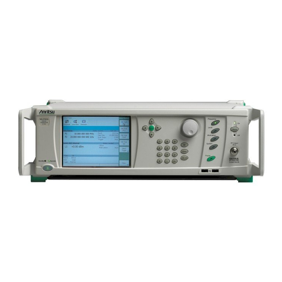
- Page 1 Operation Manual Series MG3702xA RF/Microwave Signal Generators Fast Switching Microwave Signal Generator 100 µsec Switching Speed 10 MHz to 20 GHz Anritsu Company P/N: 10370-10370 490 Jarvis Drive Revision: D Morgan Hill, CA 95037-2809 Printed: October 2013 Copyright 2013 Anritsu Company...
- Page 2 NI and NI-VISA are trademarks of the National Instruments Corporation. NOTICE Anritsu Company has prepared this manual for use by Anritsu Company personnel and customers as a guide for the proper installation, operation and maintenance of Anritsu Company equipment and computer programs. The drawings, specifications, and information contained herein are the property of Anritsu Company, and any unauthorized use or disclosure of these drawings, specifications, and information is prohibited;...
- Page 3 EULA. d. Termination. Without prejudice to any other rights, Anritsu may terminate this EULA if you fail to comply with the terms and conditions of this EULA. In such event, you must destroy all copies of the SOFTWARE PRODUCT.
- Page 5 This product and its manuals may require an Export License or approval by the government of the product country of origin for re-export from your country. Before you export this product or any of its manuals, please contact Anritsu Company to confirm whether or not these items are export-controlled.
- Page 6 Chinese RoHS Compliance Statement European Parliament and Council Directive 2002/96/EC...
-
Page 7: Table Of Contents
Contacting Anritsu ........ - Page 8 Table of Contents (Continued) Graphical User Interface Overview ..........3-4 Operating Mode Toolbar .
- Page 9 Table of Contents (Continued) Step Sweep Frequency Operation ..........4-11 Editing the Step Sweep Setup.
- Page 10 Table of Contents (Continued) 4-11 Pulse Modulation ............4-42 Accessing the Modulation Menu .
- Page 11 Some or all of the following five symbols may or may not be used on all Anritsu equipment. In addition, there may be other labels attached to products that are not shown in the diagrams in this manual.
- Page 12 For Safety Warning Always refer to the operation manual when working near locations at which the alert mark, shown on the left, is attached. If the operation, etc., is performed without heeding the advice in the operation manual, there is a risk of personal injury.
-
Page 13: Chapter 1-General Information
From here, you can select the latest sales, service and support contact information in your country or region, provide online feedback, complete a "Talk to Anritsu" form to get your questions answered, or obtain other services offered by Anritsu. -
Page 14: Instrument Description
Windows shutdown procedures and do NOT modify the operating system configuration, the firewall settings, the system registry, the hard disk drive partitions, or the Anritsu user accounts. All screen shots in this manual are shown in the standard Windows XP theme. -
Page 15: Antivirus Protection
The MG3702xA is tested with most common antivirus software, but stability is not guaranteed with all anti- virus software. Anritsu recommends connecting the instrument only to a secure network. The user assumes the responsibility to provide virus protection because this is not supplied with the instrument. Contact your network administrator for information about your network security and antivirus protection policies. - Page 16 Operating System Integrity General Information PN: 10370-10370 Revision D MG3702xA OM...
-
Page 17: Chapter 2-Preparation For Use
If the shipment is incomplete or if the signal generator is damaged mechanically or electrically, notify your local sales representative or Anritsu Customer Service. If either the shipping container is damaged or the cushioning material shows signs of stress, notify the carrier as well as Anritsu. - Page 18 Unpacking the Product Preparation for Use Figure 2-1. MG3702xA Outline Dimensions PN: 10370-10370 Revision D MG3702xA OM...
-
Page 19: Rack Mount Assembly (Option 1)
The screws with green heads have metric threads. When it becomes necessary to replace any of Note these screws, always use the exact replacement green-headed screws to avoid damage to the instrument. Anritsu PN: 905-8 (long) or Anritsu PN: Z-951102 (short). MG3702xA OM PN: 10370-10370 Revision D... - Page 20 Rack Mount Assembly (Option 1) Preparation for Use 4. Remove the inner slide assemblies from the outer slide assemblies. 5. Place the left side inner slide assembly onto the instrument case with the handle towards the front of the instrument as shown in Figure 2-3.
-
Page 21: Power Requirements
Preparation for Use Power Requirements Power Requirements The signal generator accepts 85 to 264 Vac, 48 to 440 Hz, single-phase power. Power consumption is 250 VA maximum. The signal generator is intended for Installation Category (Over Voltage Category) II. To connect the MG3702xA to the power source, plug the female end of the power cable into the input line voltage receptacle on the rear panel as shown in Figure... -
Page 22: Power On Procedure
To provide maximum protection against damage in transit, the signal generator should be repackaged in the original shipping container. If this container is no longer available and the unit is being returned to Anritsu for repair, advise Anritsu Customer Service; they will send a new shipping container free of charge. In the event neither of these two options is possible, instructions for packaging and shipment are given below: •... -
Page 23: Remote Programming Setup And Interface
The only interconnection required for GPIB operation is between the signal generator and the controller. This interconnection is via a standard GPIB cable. The Anritsu part numbers for GPIB cables are: • 2100-1, one meter long •... - Page 24 Remote Programming Setup and Interface Preparation for Use 2. Press the Config. soft key. The System Configuration menu (shown below) is displayed. Figure 2-6. System Config Menu 3. From the System Configuration menu, select the Remote tab or press the Remote... menu button to show the remote configuration menu shown below.
- Page 25 Preparation for Use Remote Programming Setup and Interface 4. In the GPIB Address area, press the Edit button and enter a new address using the data entry keypad, then press the Enter terminator button. The entry must be between 0 and 30 to be recognized as a valid GPIB address.
-
Page 26: Ethernet Interface Connection And Setup
Remote Programming Setup and Interface Preparation for Use Ethernet Interface Connection and Setup The MG3702xA fully supports the IEEE-802.3 standard. Most MG3702xA front panel functions (except power on/off) can be remotely controlled via a network server and an Ethernet connection. The MG3702xA software supports the TCP/IP network protocol. - Page 27 Preparation for Use Remote Programming Setup and Interface Table 2-1. 8-pin Ethernet RJ45 Connector Pinout Diagram Name Description Wire Color Transmit data (> +3 volts) White/Orange TX– Transmit data (< –3 volts) Orange Receive data (< –3 volts) White/Green – Not used (common mode termination) Blue –...
- Page 28 Remote Programming Setup and Interface Preparation for Use 2. Press the Config. soft key. The System Configuration menu (shown below) is displayed. Figure 2-10. System Config Menu 3. From the System Configuration menu, select the Remote tab to show the remote configuration menu shown below.
- Page 29 Preparation for Use Remote Programming Setup and Interface 4. In the Network Config area, press the Setup... button to launch the Network Connections dialog below. Figure 2-12. Network Connections 5. From the Windows Network Connections window, the New Connection Wizard or the Network Setup Wizard can be launched, or the network connection can be manually configured by right clicking the Local Area Connection name in the Network Connections window (Figure...
- Page 30 Remote Programming Setup and Interface Preparation for Use 2. In the Internet Protocol (TCP/IP) Properties dialog, manually configure the network connection with the following settings: IP address: 192.168.1.105 Subnet mask: 255.255.255.0 Figure 2-14. General Internet Protocol (TCP/IP) Properties 3. Press OK to close all open dialogs and reboot the instrument to connect to the network. 4.
-
Page 31: Usb Interface Connection And Setup
Preparation for Use Remote Programming Setup and Interface 7. Select the Basic I/O tab and execute the default *IDN? write, then execute a read. Figure 2-16. NI MAX TCP-IP Basic I/O Write/Read USB Interface Connection and Setup The Universal Serial Bus (USB) architecture is a high-performance networking standard that is considered “plug and play”... - Page 32 Remote Programming Setup and Interface Preparation for Use 4. Select to allow the Wizard to search for and install the USB software automatically. Figure 2-18. USB Found New Hardware Wizard 5. After the software installs, close the Wizard by clicking Finish. Figure 2-19.
- Page 33 Preparation for Use Remote Programming Setup and Interface The following example describes the verification that a VISA controller can see the resource. It also gives the programmer the resource string required to connect via the VISA API: 1. On the controller PC, run NI MAX and expand Devices and Interfaces. Figure 2-20.
-
Page 34: Language Options
Remote Programming Setup and Interface Preparation for Use Language Options The MG3702xA has two language options for remote programming; Standard Commands for Programmable Instrumentation (SCPI) or MG3690B. From System | Config., click on the Remote tabs then the Language Select button to change the programming language and press the Close button to confirm the selection. More information about programming in SCPI and the SCPI equivalents to MG3690B programming commands is available in the MG3702xA programming manual, PN: 10370-10371. -
Page 35: Chapter 3-Instrument Overview
Chapter 3 — Instrument Overview Introduction This chapter provides information and instructions on operating the series MG3702xA synthesized signal generator using the front panel controls. It contains illustrations of the front panel, graphical user interface, and data entry area that identify and describe all of the front panel controls. Front Panel Layout The MG3702xA front panel is divided into two main areas—the Graphical User Interface (GUI) and the data entry area. -
Page 36: Important Notes About The Rf Output Connector
Torque Requirements: Caution K (2.92 mm) Connector - Torque to 0.9 N·m (8 lbf·in) using Anritsu Model 01-201 5/16 in Torque End Wrench and Anritsu Model 01-204 - 8 mm (5/16 in) Open End Wrench V (1.85 mm) Connector - Torque to 0.9 N·m (8 lbf·in) using Anritsu Model 01-201 5/16 in Torque... -
Page 37: Data Entry Area
Instrument Overview Data Entry Area Data Entry Area The value of a selected MG3702xA parameter can be changed using the rotary data knob, cursor control keys, or data entry keys. The data entry area is identified in Figure 3-3 and described in the following paragraphs. Figure 3-3. -
Page 38: Graphical User Interface Overview
Graphical User Interface Overview Instrument Overview Graphical User Interface Overview The Graphical User Interface (GUI) is a touch-screen, liquid-crystal display (LCD). Information is presented on the LCD in the form of menu displays with interactive soft button controls. These buttons either select a menu to be displayed or control a function on the current menu display. -
Page 39: Status Bars And Parameter Areas
Instrument Overview Graphical User Interface Overview Status Bars and Parameter Areas Three shaded status bars identify each of the three parameters area. The currently selected mode of operation and status information for each operation is displayed in this status bar as follows: Frequency Setup Parameter Area: The current frequency mode (CW, Step Sweep, or List Sweep) appears on the left side of the status bar. -
Page 40: Parameter Editing Field
Graphical User Interface Overview Instrument Overview Parameter Editing Field The blue parameter editing field is used to edit most parameters such as frequency, level, and GPIB address. When a parameter is not actively selected for editing, the field is solid blue. Below is an example of several parameters being edited. -
Page 41: Front Panel Menus
Instrument Overview Front Panel Menus Front Panel Menus This section provides a comprehensive collection of front panel menus and displays. Each illustration is accompanied with a description of the functions available in the particular display. Additional navigation options may also be described; however, this section does not provide operational concepts or task examples. For details on specific operations and instrument setups, refer to Chapter 4, “Instrument Operation”. - Page 42 Front Panel Menus Instrument Overview Table 3-4. System Menus Top-level Menu Menu Page System Menu System Menu 3-17 Display Menu 3-17 Configuration Menus Rear Panel Menu 3-17 RF Menu 3-18 Remote Menu 3-18 Increment Menu 3-18 Preset Menu 3-19 Preset Select Menu 3-19 Setups Menu 3-20...
-
Page 43: Frequency Menus
Instrument Overview Front Panel Menus Frequency Menus CW Menus CW Menu Edit Frequency: Opens the CW frequency parameter field. Edit Level: Opens the level parameter field. CW Ramp: Toggles the rear panel CW Ramp On or Off. Phase Offset>>: Opens the Phase Menu. -
Page 44: Step Sweep Menus
Front Panel Menus Instrument Overview Step Sweep Menus Step Sweep Menu Edit Setup: Opens the Step Setup Menu. Step Setup Menu Auto: Sets sweep triggering to Auto. External: Sets sweep triggering to External. Single: Sets sweep triggering to Single. Trigger: When in single sweep, triggers a new sweep. Edit Start (F1): Opens the start frequency parameter field. -
Page 45: List Sweep Menus
Instrument Overview Front Panel Menus List Sweep Menus List Sweep Menu Edit Setup: Opens the List Setup Menu. Edit List: Depending on the list type, opens the List Edit Menu (Frequency List Type) List Edit Menu (Frequency + Level List Type). - Page 46 Front Panel Menus Instrument Overview List Edit Menu (Frequency List Type) Edit Frequency: Opens the selected index frequency parameter field. Go To Current Index: Moves the selection to the currently set frequency. Go To Sweep Start Index: Moves the selection to the start index position.
-
Page 47: Level Menus
Instrument Overview Front Panel Menus Level Menus Level Menu (CW & Step Sweep Freq. Mode) Edit Level: Opens the level edit parameter field. Leveling>>: Opens the Leveling Menu (not available in List Sweep mode). Attenuation>>: Opens the Attenuation Menu (not available in List Sweep mode). More>>: Opens the Level Menu (More). - Page 48 Front Panel Menus Instrument Overview Leveling Menu This menu is not available in List Sweep mode. Internal: Selects internal leveling. Fixed Gain: Selects fixed gain leveling. <<Previous: Returns to the Level Menu. Attenuation Menu This menu is not available in List Sweep mode. Decouple (On): Decouples the internal attenuator for manual attenuation control.
-
Page 49: Pulse Modulation Menus
Instrument Overview Front Panel Menus Pulse Modulation Menus Internal Pulse Modulation Menu Enable: Enables the pulse modulation from either an internal or external source. Source: Selects the pulse modulating source from either Internal or External. When external source is selected the RF On polarity can be selected between High RF On or Low RF On. - Page 50 Front Panel Menus Instrument Overview Pulse Modulation Trigger Menu Free Run: Selects continuous free run pulse triggering. External Trigger: Selects external pulse triggering. Edge: When external trigger is selected, the trigger edge can be selected between Rising or Falling. Gated: Selects gated pulse triggering. Gated triggering allows the pulse to continue during the gate cycle.
-
Page 51: System Menus
Instrument Overview Front Panel Menus System Menus The top-level System menu provides access to the System Menu following sub-level menus: Configuration Menus Setups Menus Self Test Menus Info Menus Reference Cal Menu Maintenance Menu Figure 3-16. System Menu Configuration Menus Display Menu View Desktop: Minimizes the MG3702xA software interface and shows the system desktop. - Page 52 Front Panel Menus Instrument Overview RF Menu DeltaF RF: Sets RF On or Off during frequency switching. Ramp Rest: Sets rear panel ramp voltage at ramp rest. RF Preset Default: Sets RF On or Off at preset. <<Previous: Returns to the System Menu.
- Page 53 Instrument Overview Front Panel Menus Preset Menu Power On Setup: Sets the power on setup to retrieve the last state on power down or a default setup state. Preset: Sets the preset state to retrieve the default setup state or a user defined state. Select: Opens the Preset Select Menu.
- Page 54 Front Panel Menus Instrument Overview Setups Menus Setups Menu Save: Opens the Save Setup Menu. Recall: Opens the Recall Setup Menu. Save to “Last”: Saves the current setup to the last state file. Displays the Save to Last Dialog Box. <<Previous: Returns to the System Menu.
- Page 55 Instrument Overview Front Panel Menus Recall Setup Menu Recall: Selects the highlighted setup file and returns to Setups Menu. Delete Selected: Deletes the highlighted file. Close: Returns to the System Menu. Save to Last Dialog Box Warning dialog box that selecting Yes will overwrite current data.
- Page 56 Front Panel Menus Instrument Overview Self Test Menus Self Test Menu Run Self Test: Executes the set of 13 self test routines and displays the Self Test Status Log. Advanced...: Opens the advanced tests starting with the Frequency Self Tests. <<Previous: Returns to the System Menu.
- Page 57 Instrument Overview Front Panel Menus Level Self Tests Run Enabled: Executes the enabled self test routines and displays the Selected Self Test Log. Enable/Disable All: Toggles all of the Enabled check boxes. Toggle Enable: Toggles the selected Enabled check box. Toggle Verbose: Toggles the selected Verbose check box.
- Page 58 Front Panel Menus Instrument Overview Selected Self Test Log The Self Test Log displays the results of the performed self tests. Figure 3-19. Self Test Menus (3 of 3) 3-24 PN: 10370-10370 Revision D MG3702xA OM...
-
Page 59: Info Menus
Instrument Overview Front Panel Menus Info Menus Info Menu About...: Displays the System Information Dialog Boxes. Error Log...: Displays the Error Log Menu. <<Previous: Returns to the System Menu. System Information Dialog Boxes The System Information Dialog provides a comprehensive description of the MG3702xA instrument version and configuration. -
Page 60: Reference Cal Menu
Front Panel Menus Instrument Overview Error Log Menu Details: Displays the Error Details Dialog Box. Refresh: Refreshes the error log display list. Recall Error Setup: Recalls the instrument setup from when the error occurred. Clear All: Clears all of the error log entries. Close: Returns to the Info Menu. -
Page 61: Maintenance Menu
Instrument Overview Front Panel Menus Maintenance Menu Maintenance Menu The maintenance menu is password protected and is only available to trained Anritsu service technicians. Figure 3-22. Maintenance Menus Remote Menus Remote Menu (Remote Updates On) The remote menu is displayed when the instrument is being controlled through remote programming. - Page 62 3-28 PN: 10370-10370 Revision D MG3702xA OM...
-
Page 63: Chapter 4-Instrument Operation
Chapter 4 — Instrument Operation Instrument Start-Up Once you have familiarized yourself with the layout of the MG3702xA front panel controls and data display, you are ready to begin operating the instrument. Begin by powering it up. Powering Up the MG3702xA Connect the MG3702xA to an AC power source by following the “Power On Procedure”... -
Page 64: Self Testing The Mg3702Xa
Self Testing the MG3702xA Instrument Operation Self Testing the MG3702xA The MG3702xA firmware includes internal diagnostics that self test the instrument. These self test diagnostics perform a brief go/no-go test of most of the PCBs and other internal assemblies. If the signal generator fails self test, an error message is displayed in the self test status log. - Page 65 Instrument Operation Self Testing the MG3702xA Then, when the System menu (shown above) is displayed, press Self Test>> to enter the Self Test menu. Figure 4-3. Self Test Menu From the Self Test menu, press Run Self Test. The self test results are then displayed in the self test status message log shown below.
-
Page 66: Selecting Self Tests
Self Testing the MG3702xA Instrument Operation Selecting Self Tests Selected self tests can be run individually or in groups from the Advanced self test menu, below: Figure 4-5. Self Test Advanced Menu To select the self test, toggle the Enabled check box by pressing on the check box or pressing the Toggle Enable button. -
Page 67: Resetting To Default Parameters
Instrument Operation Resetting to Default Parameters Resetting to Default Parameters You can reset the MG3702xA to the factory selected default parameter values at any time during normal operation. Resetting the instrument clears the current setup parameters. If these parameter values are needed for future testing, save them as a stored setup before resetting the signal generator. -
Page 68: Opening The Parameter
Entering Data Instrument Operation Opening the Parameter In order for the value of a parameter to be changed, the parameter edit field must first be opened. To open the frequency parameter edit field from the above menu, press Edit Frequency. The menu display changes (below) to show that the F0 parameter field is open for editing. -
Page 69: Entering A New Value
Instrument Operation Entering Data Entering a New Value To change the current value of a parameter by directly entering a new value, use the data entry keypad and termination buttons. As soon as you press one of the keys on the data entry keypad, the current parameter display clears for entry of a new value. -
Page 70: Cw Frequency Operation
CW Frequency Operation Instrument Operation CW Frequency Operation One of the signal generator's major functions is to produce discrete CW frequencies across the frequency range of the instrument. The following paragraphs describe how to place the MG3702xA in the CW frequency mode, select a CW frequency and power level for output, and activate the CW Ramp. -
Page 71: Activating The Cw Ramp
Instrument Operation CW Frequency Operation Activating the CW Ramp When active, the MG3702xA’s CW ramp provides a repetitive 0 V to 10 V ramp output to the rear panel Horizontal Output on the AUX I/O connector, pin 1. The CW ramp is used to drive a scalar analyzer display. -
Page 72: Editing The Phase Offset Setup
CW Frequency Operation Instrument Operation Editing the Phase Offset Setup The MG3702xA’s RF output can be phase shifted. The phase offset range is –360° to +360° with a resolution of 0.1°. The phase offset function is available in the CW operating mode only. The phase offset is always Note active and is a relative value compared to the current phase offset display. -
Page 73: Step Sweep Frequency Operation
Instrument Operation Step Sweep Frequency Operation Step Sweep Frequency Operation The signal generator can generate broad (full range) and narrow band sweeps across the frequency range of the instrument. In step sweep frequency mode, the output frequency changes in discrete, synthesized steps between the selected start and stop frequencies. -
Page 74: Editing The Step Sweep Setup
Step Sweep Frequency Operation Instrument Operation Editing the Step Sweep Setup To edit the step sweep, press the Edit Setup... button to display the Step Setup menu below. Figure 4-13. Step Sweep Setup Menu A Sweep Setup error message is displayed when the step size value entered is greater than the Note sweep range or the number of steps entered results in a step size of less than 0.001 Hz. -
Page 75: Setting The Number Of Steps
Instrument Operation Step Sweep Frequency Operation Setting the Number of Steps The number of steps range is 1 to 10,000. If the step size does not divide into the frequency range, the last step is truncated. When the step Dwell Time, Step Size, or Number of Steps is set: sweep time = Step Dwell time ×... -
Page 76: List Sweep Frequency Operation
List Sweep Frequency Operation Instrument Operation List Sweep Frequency Operation In list sweep mode, the output is a step sweep of up to 10,001 phase-locked, non-sequential frequencies. Each frequency can have a different power level setting. The list index (0 through 10,000) identifies each frequency/power level set in the list. -
Page 77: Editing The List Sweep Setup
Instrument Operation List Sweep Frequency Operation Editing the List Sweep Setup To edit the list sweep setup, press the Edit Setup... button to display the List Setup menu below. Figure 4-15. List Setup Menu This menu lets you perform the following actions: •... -
Page 78: Editing The Current Index Frequency
List Sweep Frequency Operation Instrument Operation Editing the Current Index Frequency Press the Frequency menu button to open the index frequency parameter field for editing. Edit the current list frequency using the cursor control keys, rotary data knob, or enter a new value using the keypad and appropriate termination. -
Page 79: Selecting The List Type
Instrument Operation List Sweep Frequency Operation Selecting the List Type There are two available list types that can be accessed from the List Setup menu (Figure 4-15). Press the Type>> button to display the List Type menu below. Figure 4-16. List Sweep Setup Menu Select Frequency List to set a fixed power level for all of the list frequency values. -
Page 80: Editing The List
List Sweep Frequency Operation Instrument Operation Editing the List The list consists of 10,001 index entries. From the List Sweep menu, press Edit List... The List Edit menu that is displayed below is for a frequency +level list. Figure 4-17. List Sweep Setup Menu This menu lets you scroll through and edit the list of frequencies and power levels. -
Page 81: Power Leveling Operations
Instrument Operation Power Leveling Operations Power Leveling Operations The MG3702xA provides main band leveled output power over a maximum range of up to 24 dB (up to 123 dB with Option 2) for CW and sweep frequency operations. Instruments with Option 15 provide leveled output power over a maximum range of up to 28 dB (up to 123 dB with Option 2). -
Page 82: Setting Up A Power Level Offset
Power Leveling Operations Instrument Operation Setting up a Power Level Offset Level offset lets you compensate for a device on the signal generator's output that alters the RF output power level at the point of interest. For example, the power level at the test device may be less or more than the displayed power level because of the loss through an external transmission line or the gain of an amplifier located between the MG3702xA RF output and the test device. -
Page 83: Internal Leveling
Instrument Operation Power Leveling Operations The Leveling menu lets you select a leveling mode. To access the Leveling menu, press the Level Mode toolbar button and select Level. From the Level menu, press the Leveling>> button. The Leveling menu (below) is displayed. Figure 4-20. -
Page 84: Decoupling The Attenuator
Power Leveling Operations Instrument Operation Decoupling the Attenuator In MG3702xAs equipped with Option 2 step attenuators, the ALC and attenuator work in conjunction to provide leveled output power down to –105 dBm. In the normal (coupled) leveling mode, when the desired power level is set, the correct combination of ALC level and attenuator setting is determined by the instrument firmware. -
Page 85: System Configurations
Instrument Operation System Configurations System Configurations The system configuration function provides menus to set instrument configuration items. Configuration and setup menus are accessed from the main system menu shown below by pressing the System key. Figure 4-22. System Menu Accessing the System Configuration Menu To access the System Configuration menu, press System. -
Page 86: Configuring The Display
System Configurations Instrument Operation The system Configuration menu provides access to a variety of instrument configurations as described in the following sections: • “Configuring the Display” on page 4-24 • “Secure Mode Operation” on page 4-25 • “Calibrating the Touch Screen” on page 4-27 •... -
Page 87: Secure Mode Operation
Instrument Operation System Configurations Secure Mode Operation The MG3702xA can be operated in a secure mode where the display of all frequency and power level parameters are disabled during both local (front panel) and remote (GPIB) operations. When in secure mode, the instrument continues to function normally in all other respects. - Page 88 System Configurations Instrument Operation The display in Secure mode is shown below. Figure 4-26. Sample Secure Mode CW Menu To return the MG3702xA to unsecured (normal) operation, press the front panel Preset button. 4-26 PN: 10370-10370 Revision D MG3702xA OM...
-
Page 89: Calibrating The Touch Screen
Instrument Operation System Configurations Calibrating the Touch Screen The MG3702xA’s front panel touch screen can be calibrated to improve the accuracy of the touch screen. To calibrate the touch screen, enter the display configuration menu shown below by pressing System | Confi. | Display... Figure 4-27. - Page 90 System Configurations Instrument Operation Press the Touch Screen Calibration Config... button shown in Figure 4-27 and follow the on-screen instructions found on the control panel shown below to start the automatic calibration function. Figure 4-28. Touch Screen Control Panel Select the Calibration tab before the countdown expires for manual calibration. The following screen is displayed, which offers additional calibration configurations and touch-screen tests.
- Page 91 Instrument Operation System Configurations The calibration routine will continue as shown below. Touch and hold the center of the target for each step of the calibration process as directed in the on-screen display. After this step, test the calibration by dragging the target around the screen as instructed.
-
Page 92: Configuring The Rear Panel
System Configurations Instrument Operation Configuring the Rear Panel Figure 4-31. Rear Panel Configuration Menu Configuring the rear panel of the signal generator consists of setting the polarity of the retrace and bandswitch blanking signals. Press Blanking + or – to select a +5 V or –5 V level for the retrace and bandswitch blanking outputs. -
Page 93: Configuring The Rf
Instrument Operation System Configurations Configuring the RF Figure 4-32. RF Configuration Menu Configuring the RF of the MG3702xA involves the following: • DeltaF RF: Selects RF On or Off during frequency switching. Selecting DeltaF RF Off significantly improves spurious performance. •... -
Page 94: Configuring The Remote Interface
System Configurations Instrument Operation Configuring the Remote Interface Figure 4-33. Remote Configuration Menu The Remote configuration menu lets you set the following: • GPIB Address: Press the Edit button to change the address of the MG3702xA on the bus (the default GPIB address is five). Enter a new address, between 0 and 30, using the cursor control keys or the data entry keypad and the Enter button. -
Page 95: Setting The Increment Size
Instrument Operation System Configurations Setting the Increment Size Figure 4-34. Increment Configuration Menu The Increment menu is not available at this time. Press << Previous to return to the System menu. MG3702xA OM PN: 10370-10370 Revision D 4-33... -
Page 96: Configuring Preset Conditions
System Configurations Instrument Operation Configuring Preset Conditions Figure 4-35. Preset Configuration Menu The Preset configuration menu provides access to the following: • Power On Setup: Sets the instrument to recall the last power down configuration or the selected preset configuration when brought back into operation from standby or power down. 4-34 PN: 10370-10370 Revision D MG3702xA OM... - Page 97 Instrument Operation System Configurations • Preset: Provides for selecting the preset configuration as either the factory default configuration or a user defined configuration. Press the Select button to open the Preset Select menu below. Figure 4-36. Preset Select Menu Use the navigation controls to select the desired user preset file (highlighted in reverse video), then press the Select button.
-
Page 98: System Setups
System Configurations Instrument Operation System Setups The MG3702xA offers the capability to store instrument setups. The setups are stored as .XML files on the instrument’s hard drive. The following paragraphs describe how to save and recall front panel setups. Saving System Setups 1. - Page 99 Instrument Operation System Configurations Figure 4-38. Save Setup Menu 4. Enter the desired filename using the keypad, then press the Save button. Alternatively, you can select an existing filename by pressing the Select File Name button and selecting the setup file from the Select menu below. Figure 4-39.
-
Page 100: Recalling Stored Setups
System Configurations Instrument Operation Recalling Stored Setups To recall a previously saved setup file, first access the Setups menu as described below: 1. Press System to display the System menu, then press the Setups>> button. The Setups menu below is displayed. Figure 4-40. -
Page 101: Deleting Stored Setups
Instrument Operation System Configurations Deleting Stored Setups A highlighted stored setup can be deleted from the Recall Setup menu (described above) by pressing the Delete Selected button. When pressing the Delete Selected button, the highlighted file is deleted from the instrument’s hard Caution drive and cannot be recovered. -
Page 102: 4-10 Reference Loop Adjustments
Reference Loop Adjustments Instrument Operation 4-10 Reference Loop Adjustments The signal source reference loop can be calibrated to an external reference source by following the calibration procedure below. Calibrating the Reference Oscillator The reference oscillator calibration function lets you calibrate the internal 100 MHz crystal reference oscillator of the MG3702xA using an external 10 MHz, 0 dBm to +10 dBm reference signal. - Page 103 Instrument Operation Reference Loop Adjustments 4. Press Next to begin the calibration and follow the on-screen instructions. Figure 4-44. Frequency Reference Calibration When the reference calibration is in process, the calibration status is shown on the menu. When the reference calibration is complete, the calibration status is displayed as shown below.
-
Page 104: Pulse Modulation
Pulse Modulation Instrument Operation 4-11 Pulse Modulation The MG3702xA provides pulse modulation (Option 26) of the output signal using modulating signals from either its internal pulse generator or external sources that are TTL-compatible. To provide pulse modulation of the output signal using a modulating signal from an external source, set up the external pulse generator and connect it to the MG3702xA rear panel PULSE TRIG IN connector. -
Page 105: Providing Internal Pulse Modulation
Instrument Operation Pulse Modulation Providing Internal Pulse Modulation Press the Source Internal button to select the internal pulse generator as the modulating signal source. Press the On or Off buttons to turn pulse modulation on and off. The Pulse status display area reflects your selection as On or Off. -
Page 106: Selecting The Pulse Mode
Pulse Modulation Instrument Operation Selecting the Pulse Mode Select the pulse mode by pressing the Mode>> button. Figure 4-48. Pulse Mode Menu Refer to Figure 4-50 on page 4-46 for illustrations of each pulse mode. Select from the following pulse modes: •... -
Page 107: Selecting The Pulse Triggering
Instrument Operation Pulse Modulation Selecting the Pulse Triggering From the Pulse menu, press the Trigger>> button to access the pulse Trigger menu below. Figure 4-49. Pulse Triggering Menu Refer to Figure 4-50 on page 4-46 for illustrations of each triggering mode. Select from the following pulse modes: •... - Page 108 Pulse Modulation Instrument Operation Figure 4-50. Pulse Pattern and Trigger Relationships 4-46 PN: 10370-10370 Revision D MG3702xA OM...
-
Page 109: Providing External Pulse Modulation
Instrument Operation Optimizing Frequency Switching Time Providing External Pulse Modulation To provide pulse modulation of the output signal using a modulating signal from an external source, first set up the external pulse generator and connect it to the MG3702xA rear panel PULSE TRIGGER IN connector. Next, access the Pulse menu and select the External pulse source to select the external source for the modulating signal as shown below. - Page 110 4-48 PN: 10370-10370 Revision D MG3702xA OM...
-
Page 111: Chapter 5-Operation Verification
Specifications shown in this chapter and in other chapters are for reference only. Refer to the performance specifications for the MG3702xA found in the technical data sheet that was shipped with your instrument; Anritsu part number: 11410-00429. Test Equipment Table 5-1 lists the recommended test equipment for performing the operation verification tests in this chapter. -
Page 112: Power Up
Initial MG3702xA Checkout Operation Verification Power Up Connect the MG3702xA to the power source and turn on the rear panel power switch. This automatically places the signal generator in operation (front panel Operate LED green). During power up, the signal generator loads its operating program, and then returns to the specified power on setup file. - Page 113 Operation Verification Initial MG3702xA Checkout From the System menu, press Self Test to enter the Self Test menu. Figure 5-2. Self Test Menu From the Self Test menu, press Run Self Test. After the self test runs, the results are displayed in the self test status message log as shown below.
-
Page 114: Presetting The Mg3702Xa
Initial MG3702xA Checkout Operation Verification Presetting the MG3702xA The signal generator should be preset to the factory-selected default parameters before commencing operation verification testing. Ensure that the default Preset configuration is selected from the System | Configuration | Preset menu below: Figure 5-4. -
Page 115: Frequency Synthesis Test
Operation Verification Frequency Synthesis Test Frequency Synthesis Test The following test verifies that the CW frequency output of the MG3702xA under test is within tolerance. Table 5-2 contains a standard test record that you can copy and use to record test results for this test. Figure 5-5. - Page 116 Frequency Synthesis Test Operation Verification Table 5-2. Frequency Synthesis Test Record Model MG3702xA Serial Number: Date: Test Frequency F0 (GHz) Recorded Frequency (GHz) Calculated Difference (Hz) COURSE FREQUENCY SETTINGS 2.000 000 000 000 5.000 000 000 000 8.000 000 000 000 11.000 000 000 000 14.000 000 000 000 17.000 000 000 000...
-
Page 117: Level Accuracy And Flatness Test
Operation Verification Level Accuracy and Flatness Test Level Accuracy and Flatness Test The following tests verify that the power level accuracy and flatness of the MG3702xA meet specifications. Table 5-3 Table 5-4 contain test records that you can copy and use to record test results. Figure 5-6. -
Page 118: Power Level Accuracy Test Procedure
Level Accuracy and Flatness Test Operation Verification 3. Connect the special AUX I/O interface cable (Anritsu PN 806-97) to the MG3702xA rear panel AUX I/O connector. Connect the cable BNC connectors as follows: a. Connect the cable labeled “SEQ SYNC” to the power meter rear panel INPUT 1 DIGITAL connector. - Page 119 Operation Verification Level Accuracy and Flatness Test Table 5-3. Power Level Accuracy Test Record Model MG3702xA Serial Number: Date: Power Level Accuracy Power Level Accuracy Power Level Accuracy (CW Frequency = 500 MHz) (CW Frequency = 5.0 GHz) (CW Frequency = 15.0 GHz) Measured Measured Measured...
-
Page 120: Power Level Flatness Test Procedure
Level Accuracy and Flatness Test Operation Verification Power Level Flatness Test Procedure Power level flatness is checked by measuring the power level variation during a full band sweep in the step sweep mode. 1. Set up the MG3702xA as follows for a step sweep power level flatness test: a. - Page 121 Operation Verification Level Accuracy and Flatness Test Table 5-4. Power Level Flatness Test Record Model MG3702xA Serial Number: Date: Set Power Maximum Power Minimum Power Variation +0 dBm Maximum variation is 1.6 dB for standard power instruments and 3.0 dB for high power (Option 15) instruments. MG3702xA OM PN: 10370-10370 Revision D 5-11...
- Page 122 5-12 PN: 10370-10370 Revision D MG3702xA OM...
-
Page 123: Chapter 6-Operator Maintenance
Chapter 6 — Operator Maintenance Introduction This chapter provides the information necessary for operator maintenance of the signal generator. Operator maintenance is limited to troubleshooting and repairs that can be made without removing the instrument covers. Error and Warning Status Messages During normal operation, the MG3702xA generates operational status error messages to indicate internal malfunctions, abnormal signal generator operations, or invalid signal inputs or data entries. - Page 124 Error and Warning Status Messages Operator Maintenance Table 6-1. Self-Test Error Messages (1 of 2) Error Message Description/Remarks Error 100 DVM Ground Offset Indicates self test failed because of a calibration-related problem. Indicates that either a calibration-related problem or a defective +10 Volt Error 101 DVM Positive 10V reference.
- Page 125 Operator Maintenance Error and Warning Status Messages Table 6-1. Self-Test Error Messages (2 of 2) Error Message Description/Remarks Error 170 ALC RAM Device Indicates a failure while testing A6 PCB RAM device. Error 171 Processor Battery Indicates that the battery voltage on the A2 PCB is out of tolerance. Indicates that the A6 loop amp voltage is out of tolerance at a level of at Error 172 Core ALC least 3 db lower than the rated tolerance of 12 db.
-
Page 126: Troubleshooting Procedures
Troubleshooting Procedures Operator Maintenance Troubleshooting Procedures This section provides procedures for troubleshooting common malfunctions encountered during operation of the signal generator. Included are procedures for troubleshooting faults that do not produce error messages, such as, failure to power up and unexpected shutdown. Signal Generator will not turn on (Operate LED is OFF) When the MG3702xA is connected to the power source and the rear panel power switch turned on, the Operate LED should illuminate and the instrument should power up. -
Page 127: Routine Maintenance
Operator Maintenance Routine Maintenance Routine Maintenance Routine maintenance that you can perform consists of cleaning the fan filters, cleaning the data display, and replacing a defective line fuse(s). Cleaning the Fan Filters The signal generator must always receive adequate ventilation. A blocked fan filter can cause the instrument to overheat and shut down. - Page 128 PN: 10370-10370 Revision D MG3702xA OM...
-
Page 129: Appendix A-Rear Panel Connectors
Appendix A — Rear Panel Connectors A-1 Introduction This appendix provides descriptions for the rear panel connectors on a typical Series MG3702xA RF/Microwave signal generator. A-2 Rear Panel Connectors Table A-1 provides an illustration of the rear panel connectors and describes the rear panel connectors. Note Connectors are option dependent. - Page 130 Connector Pin-Out Diagrams Table A-1. Rear Panel Connectors, Series MG3702xA Synthesized Signal Generator (1 of 2) Index Description 100 MHz IN (Option 36): Accepts a 100 MHz reference signal from another MG3702xA with Option 36. This input is only intended for use with other Option 36 instruments. 100 MHz OUT (Option 36): Provides the reference signal to drive up to three other MG3702xA.
- Page 131 Connector Pin-Out Diagrams Table A-1. Rear Panel Connectors, Series MG3702xA Synthesized Signal Generator (2 of 2) Index Description EFC IN: Electronic Frequency Control input accepts an external dc signal (–5 V to +5 V) to modulate the RF output. Sensitivity: 10/n kHz/V where n is the reference multiplier and the modulation bandwidth is 250 Hz.
- Page 132 Connector Pin-Out Diagrams Table A-2. Rear Panel AUX I/O Connector (1 of 2) Name Description Horizontal Sweep Output: Provides a 0V at beginning and +10V at end of sweep for all sweep modes, regardless of sweep width. In the CW mode, the voltage is proportional to frequency between HORIZ OUTPUT 0V at low end and +10V at the high end of range.
- Page 133 Connector Pin-Out Diagrams Table A-2. Rear Panel AUX I/O Connector (2 of 2) Name Description AUX 2 Not used. Band Switch Blanking Output: Provides a +5V or –5V signal BAND SWITCH BLANK coincident with band switching points. Signal polarity is selected from a front panel menu.
- Page 134 Connector Pin-Out Diagrams Table A-3. Rear Panel IEEE-488 GPIB Connector Name Description Data Input/Output. Bits are HIGH when the data is logical 0 and DIO 1 through DIO 4 LOW when the data is logical 1. End or Identify. A low-true state indicates that the last byte of a multi byte message has been placed on the line.
- Page 135 Connector Pin-Out Diagrams Table A-4. Rear Panel Serial I/O Connector Name Description Data Carrier Detect Receive Data Transmit Data Data Terminal Ready Signal Ground Data Set Ready Request to Send Clear to Send Ring Indicator Table A-5. Ethernet RJ45 Connector Name Description Transmit data (>...
- Page 136 Connector Pin-Out Diagrams Table A-6. 15-pin VGA Connector Name Description Red Video (75 Ω, 0.7 V Green Video (75 Ω, 0.7 V Green Blue Video (75 Ω, 0.7 V Blue Monitor ID Bit 2 Ground RGND Red Ground GGND Green Ground BGND Blue Ground Connector Orientation Key...
- Page 137 Connector Pin-Out Diagrams Table A-7. USB Type A Connector Name Description +5 volts, 500 mA –Data Data input +Data Data output Ground Table A-8. USB Type B Connector Name Description +5 volts, 500 mA –Data Data input +Data Data output Ground MG3702xA OM PN: 10370-10370 Revision D...
- Page 138 A-10 PN: 10370-10370 Revision D MG3702xA OM...
-
Page 139: Appendix B-Performance Specifications
In the printed manuals, this appendix includes the technical data sheet for the series MG3702xA RF/Microwave Signal Generator, part number: 11410-00429. Electronic manuals do not contain this data sheet. The latest electronic copy of this data sheet may be downloaded from the Anritsu Internet site at: http://www.us.anritsu.com MG3702xA OM... - Page 140 PN: 10370-10370 Revision D MG3702xA OM...
- Page 141 Connector Care ......3-2 contacting Anritsu ......1-1 conventions, typographic .
- Page 142 G to M frequency list ....... . . 4-17 keys, menu .......3-2 of list index .
- Page 143 N to R menu ........3-17 attenuation ......3-14 network cal .
- Page 144 S to T rear panel setups configuring ......4-30 deleting ......4-39 connectors .
- Page 145 U to Z updated documents ......1-1 ventilation ....... .2-1 updated manuals .
- Page 146 Index-6 MG369xC...
- Page 148 Printed on Recycled Paper with Vegetable Soybean Oil Ink Anritsu Company 490 Jarvis Drive Morgan Hill, CA 95037-2809 http://www.anritsu.com...
Need help?
Do you have a question about the MG3702xA Series and is the answer not in the manual?
Questions and answers