
Related Manuals for Anritsu MG369 Series


Summary of Contents for Anritsu MG369 Series
- Page 1 SERIES MG369XB SYNTHESIZED SIGNAL GENERATORS OPERATION MANUAL P/N: 10370-10365 REVISION: D 490 JARVIS DRIVE PRINTED: MARCH 2007 MORGAN HILL, CA 95037-2809 COPYRIGHT 2007 ANRITSU CO.
- Page 2 WARRANTY The Anritsu product(s) listed on the title page is (are) warranted against defects in materials and workmanship for three years from the date of shipment. Anritsu's obligation covers repairing or replacing products which prove to be defective during the warranty period.
- Page 5 Safety Symbols To prevent the risk of personal injury or loss related to equipment malfunction, Anritsu Company uses the following symbols to indicate safety-related information. For your own safety, please read the information carefully BEFORE operating the equipment. WARNING WARNING indicates a hazard. It calls attention to a procedure that could result in personal injury or loss of life if not performed properly.
- Page 6 For Safety WARNING When supplying power to this equipment, always use a three-wire power cable connected to a three-wire power line outlet. If power is supplied without grounding the equip- ment in this manner, there is a risk of receiving a severe or fatal electric shock.
-
Page 7: Table Of Contents
Table of Contents Chapter 1 General Information Scope of Manual ......1-3 Introduction ......1-3 Description . - Page 8 Preparation for Shipment ....2-13 Anritsu Service Centers ..... . . 2-14 Chapter 3 Local (Front Panel) Operation Introduction .
- Page 9 Table of Contents (Continued) Sweep Frequency Operation ..... 3-26 Analog Sweep Mode ..... 3-26 Selecting Analog Sweep Mode .
- Page 10 Table of Contents (Continued) 3-12 System Configuration......3-76 Accessing the System Configuration Menu ..3-76 Configuring the Front Panel .
- Page 11 Table of Contents (Continued) Chapter 5 Operation Verification Introduction ......5-3 Test Equipment .
- Page 12 Table of Contents (Continued) Chapter 7 Use With Other Instruments Introduction ......7-3 Master-Slave Operation .
- Page 13 Chapter 1 General Information Table of Contents Scope of Manual ......1-3 Introduction ......1-3 Description .
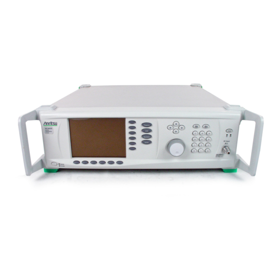
- Page 14 Figure 1-1. Series MG369XB Synthesized Signal Generator MG369XB OM...
-
Page 15: Scope Of Manual
(GPIB). Table 1-1, page 1-5, lists models, frequency ranges, and maxi- mum leveled output. Identification All Anritsu instruments are assigned a unique six-digit ID number, such as “020312”. The ID number is imprinted on a decal that is af- Number fixed to the rear panel of the unit. -
Page 16: Electronic Manual
The Anritsu part number for the main- tenance manual is 10370-10367. Options The series MG369XB synthesizer provides a wide array of instrument configurations through a series of base model and option choices. - Page 17 General Information Options Table 1-1. Series MG369XB Model and Option List (1 of 2) Model Frequency Configuration Number Range ³0.01 – £10.0 GHz With Option 4 or 5 MG3691B ³2.0 – £10.0 GHz Standard ³0.01 – £20.0 GHz With Option 4 or 5 MG3692B ³2.0 –...
- Page 18 26 and 27, offering internal and external AM, FM, FM, and Pulse Modulation. (This option comes in different Option 28X*: versions , based on instrument configuration.) Option 30: Low Phase Noise * May not be availlable for all instruments or may require additional upgrades. Contact Anritsu customer service for details. MG369XB OM...
-
Page 19: Performance Specifications
Option 91 (26.5 to 40 GHz) Mixer Option 92 (40 to 60 GHz) Option 93 (60 to 90 GHz) Power Meter, Range: –30 to +20 dBm Anritsu Model ML2437A or ML2438A, with (1mW to 100 mW) with Power Power Sensor: MA2474A (0.01 to 40 GHz) - Page 21 Preparation for Shipment ....2-13 Anritsu Service Centers ..... . . 2-14...
-
Page 23: Introduction
Anritsu Customer Service. If either the shipping container is damaged or the cushioning material shows signs of stress, notify the carrier as well as Anritsu. Keep the shipping materials for the carrier's inspec- tion. Preparation For Use... -
Page 24: Preparation For Use
Preparation For Use Installation Figure 2-1. MG369XB Outline Dimensions (in millimeters) MG369XB OM... -
Page 25: Rack Mounting Kit Installation
Installation Rack Mounting Kit Installation Rack Mounting Kit The rack mounting kit (Option 1A) contains a set of track slides (90° tilt capability), mounting ears, and front panel handles for mounting Installation the signal generator in a standard equipment rack. The following pro- cedure provides instructions for installing the rack mounting hard- ware on to the instrument. - Page 26 Rack Mounting Kit Installation Installation Step 3. Remove the inner slide assemblies from the outer slide assemblies. Step 4. Place the left side inner slide assembly onto the instrument case with the handle NOTE towards the front of the instrument (Fig- The screws with green heads have ure 2-4).
- Page 27 Installation Rack Mounting Kit Installation Step 9. Place the right side inner slide assembly onto the instrument case with the handle towards the front of the instrument. Step 10. Insert two green-headed screws through the holes in the slide assembly behind the handle and into the metric tapped holes in the side of the instrument.
-
Page 28: Power Requirements
Rack Mounting Kit Installation Installation WARNING When supplying power to this equipment, always use a three-wire power cable connected to a three-wire power line outlet. If power is supplied without grounding the equip- ment in this manner, there is a risk of receiving a severe or fatal electric shock. -
Page 29: Standby Operation
Installation Rack Mounting Kit Installation CAUTION Before installing the MG369XB in its operating environ- ment, ensure that all airflow passages at the sides and rear of the instrument are clear. This is of particular importance whenever the unit is being rack-mounted. Keep the cooling fan filters clean so that the ventilation holes are not obstructed. -
Page 30: Gpib Setup And Interconnection
Interconnection tion is between the signal generator and the control- ler. This interconnection is via a standard GPIB cable. The Anritsu part number for such a cable is 2100-1, -2, or -4 (1, 2, or 4 meters in length). 2-10... -
Page 31: Setting The Gpib Address
Installation GPIB Setup and Interconnection Setting the The default GPIB address is five. If a different GPIB GPIB Address address is desired, it can be set from the front panel using the Configure GPIB menu. To change the GPIB address, first press the front panel main menu key labeled System . -
Page 32: Selecting The Line Terminator
GPIB Setup and Interconnection Installation Selecting the Data is delimited on the GPIB by either the carriage Line return (CR) ASCII character or both the carriage re- Terminator turn and line feed (CR/LF) ASCII characters. Which character is used depends upon the requirements of the system controller. -
Page 33: Preparation For Storage/Shipment
Seal the carton by using either shipping tape or an industrial stapler. Address the Container If the instrument is being returned to Anritsu for service, mark the address of the appropriate Anritsu service center (Table 2-1, following page) and your return address on the carton in one or more promi- nent locations. -
Page 34: Anritsu Service Centers
Anritsu Service Centers Installation Anritsu Service Table 2-1, below, lists the contact information for Anritsu service cen- ters around the world. Centers Table 2-1. Anritsu Service Centers UNITED STATES FRANCE JAPAN ANRITSU COMPANY ANRITSU S.A ANRITSU CUSTOMER SERVICES 490 Jarvis Drive 9 Avenue du Quebec LTD. - Page 35 Chapter 3 Local (Front Panel) Operation Table of Contents Introduction ......3-5 Typographic Conventions .
- Page 36 Table of Contents (Continued) CW Frequency Operation..... . . 3-20 Selecting CW Mode ..... 3-20 Selecting a CW Frequency .
- Page 37 Table of Contents (Continued) 3-11 Leveling Operations ......3-63 Selecting a Leveling Mode ....3-63 Attenuator Decoupling .
-
Page 39: Introduction
Chapter 3 Local (Front Panel) Operation Introduction This chapter provides information and instructions on operating the series MG369XB synthesized signal generator using the front panel controls. It contains the following: Illustrations and diagrams of the front panel, data display area, and data entry area that identify and describe all front panel controls An annotated diagram of the menu display format showing... -
Page 40: Front Panel Layout
Front Panel Layout Local (Front Panel) Operation Front Panel Layout The MG369XB front panel is divided into two main areas—the data display area and the data entry area. The following paragraphs pro- vide a brief description of the front panel controls and data display and data entry areas as shown in Figure 3-1. -
Page 41: Data Entry Area
Local (Front Panel) Operation Front Panel Layout Data Entry The data entry area consists of data entry keys and Area controls that provide for changing values for each MG369XB parameter. RF Output The RF output control key provides for turning the Control Key RF output power on and off. -
Page 42: Data Display Area
Data Display Area Local (Front Panel) Operation Data Display Area The data display area consists of the data display and the surrounding menu keys. The data display is a liquid crystal display (LCD). Information is presented on the LCD in the form of menu displays. The menu keys either select the main menu to be displayed, select a sub-menu of the current menu display, or control a function on the current menu display. -
Page 43: Menu Display Format
Local (Front Panel) Operation Data Display Area Menu Display The menu display is divided into specific areas that Format show the frequency and power level information for the current signal generator setup. Menu labels for the current menu's soft-keys appear along the bottom and right side of the display. -
Page 44: Menu Keys
Data Display Area Local (Front Panel) Operation Instrument Warning/Status Areas These areas show instrument warning and status messages. For example, the message COLD indi- cates that the 100 MHz crystal oven has not yet reached a stable operating temperature. Menu Labels Each of the menu soft-keys, located at the bottom and right edge of the display, has a corresponding menu label area on the display. - Page 45 Local (Front Panel) Operation Data Display Area Main Menu Keys Each of the main menu keys, shown to the left, se- lects a main (top-level) menu display. These menus let you select the operating mode and configuration of the instrument. Main menu keys are identified throughout this manual by using reverse text, for example: Frequency...
-
Page 46: Data Entry Area
Data Entry Area Local (Front Panel) Operation Data Entry Area The value of a selected MG369XB parameter can be changed using the rotary data knob, cursor control keys, or keys of the data entry area. Each element of the data entry area is identified in Figure 3-3 and de- scribed in the following paragraphs. - Page 47 Local (Front Panel) Operation Data Entry Area Rotary Data Knob The rotary data knob can be used to change the value of a parameter that is open for editing. The cursor is moved under the open parameter using the < and > cursor control keys. Then, by slowly turning the knob clockwise or counterclockwise the value of the parameter is increased or decreased by the unit size.
-
Page 48: Instrument Start-Up
MG3696B RF/Microwave Signal Generator Firmware Version 1.00 COPYRIGHT 2000 - 2004 Anritsu Co. The MG369XB then returns to the exact configura- tion it was in when last set to Standby. Standby Whenever the signal generator is not being used, it... -
Page 49: Self-Testing The Mg369Xb
Local (Front Panel) Operation Instrument Start-Up Self-Testing The MG369XB firmware includes internal diagnos- the MG369XB tics that self-test the instrument. These self-test di- agnostics perform a brief go/no-go test of most of the PCBs and other internal assemblies. If the signal generator fails self-test, an error message is dis- played on the data display. - Page 50 Instrument Start-Up Local (Front Panel) Operation Table 3-1. Reset (Default) Parameters FREQUENCY PARAMETERS (GHz) MODEL NUMBER M0 M1 M2 M3 M4 M5 M6 M7 M8 M9 MG3691B 3.5 2.0 8.4 2.0 5.0 8.0 8.4 8.4 8.4 8.4 3.5 2.0 8.4 2.0 5.0 8.0 8.4 8.4 8.4 8.4 1.0 MG3692B 3.5 2.0 20.0 2.0...
-
Page 51: Entering Data
Local (Front Panel) Operation Entering Data Entering Data Before proceeding to the various modes of signal generator operation, you need to know how to enter data from the front panel. Entering data refers to changing a parameter's value by editing its current value or entering a new value to replace the current value. -
Page 52: Editing The Current Value
Entering Data Local (Front Panel) Operation Only one parameter can be open at a time. If you press Edit L1 , then the frequency parameter will close and the power level parameter will open. Editing the To change the current value of a parameter by edit- Current Value ing, you can also use either the cursor control keys or the rotary data knob. -
Page 53: Entering A New Value
Local (Front Panel) Operation Entering Data Entering a To change the current value of a parameter by en- New Value tering a new value for the parameter, use the data entry keypad and termination keys. As soon as you press one of the keys on the data en- try keypad, the current parameter display clears for entry of a new value. -
Page 54: Cw Frequency Operation
CW Frequency Operation Local (Front Panel) Operation CW Frequency One of the signal generator's major functions is to produce discrete CW frequencies across the frequency range of the instrument. The fol- Operation lowing paragraphs describe how to place the MG369XB in the CW fre- quency mode, select a CW frequency and power level for output, and activate the CW ramp and Phase Offset menus and functions. - Page 55 Local (Front Panel) Operation CW Frequency Operation Editing the Current Frequency Press Edit F1 [F1] to open the frequency parameter, then edit the current CW frequency using the cursor control keys or the rotary data knob. To close the open frequency parameter, press Edit F1 or make another menu selection.
-
Page 56: Selecting A Power Level
CW Frequency Operation Local (Front Panel) Operation Frequency List—To access the Frequency List menu (below), press Frequency List... from the Fre- quency Control menu. This menu lets you tag, edit, or output a frequency from the list. Use the cursor control keys to select a frequency from the frequency list. -
Page 57: Cw Ramp
Local (Front Panel) Operation CW Frequency Operation Editing the Current Power Level Press Edit L1 [XL1] to open the power level parame- ter, then edit the current power level using the cur- sor control keys or rotary data knob. To close the open power level parameter, press Edit L1 or make another menu selection. -
Page 58: Phase Offset
CW Frequency Operation Local (Front Panel) Operation Phase Offset When active, the MG369XB's RF output will be phase shifted by the specified amount displayed in the phase offset parameter. The phase offset range is -360° to +360° with a resolution of 0.1°. NOTE The phase offset function is available in CW op- erating mode only. -
Page 59: Electronic Frequency Control
Local (Front Panel) Operation CW Frequency Operation While the phase offset is on, the phase offset value is displayed in the CW menu (below). The phase offset value may be zeroed. This allows you to normalize the phase offset display as appro- priate. -
Page 60: Sweep Frequency Operation
Sweep Frequency Operation Local (Front Panel) Operation Sweep Frequency The signal generator can generate broad (full range) and narrow band sweeps across the frequency range of the instrument. The MG369XB Operation has four sweep frequency modes—analog sweep, step sweep, manual sweep, and list sweep. -
Page 61: Setting Sweep Time
Local (Front Panel) Operation Sweep Frequency Operation This menu lets you perform the following: Select a sweep range Set the sweep time Access the Trigger menu Select an output power level for the sweep Access the Alternate Sweep menu Setting Sweep To set the analog sweep time, from the Analog Time Sweep menu, press Sweep Time [SWT]. -
Page 62: Step Sweep Mode
Sweep Frequency Operation Local (Front Panel) Operation Step Sweep In step sweep frequency mode, the output frequency Mode changes in discrete, synthesized steps between the selected start and stop frequencies. Step sweeps can be from a low frequency to a high frequency and from a high frequency to a low frequency. -
Page 63: Setting Step Size, Dwell Time, And Sweep Time
Local (Front Panel) Operation Sweep Frequency Operation Setting Step In linear step sweep, the sweep is linearly incre- Size, Dwell mented (or decremented) by the step size from the Time, and start frequency to the stop frequency. There are two Sweep Time ways to set the size of each step of the linear step sweep—set the step size or set the number of steps. - Page 64 Sweep Frequency Operation Local (Front Panel) Operation Press More > to access the Additional Step Sweep menu (below). This menu lets you perform the following: Set the sweep time Set the number of steps Access the Trigger menu Select log or linear sweep Access the Alternate Sweep menu Press Sweep Time [SWT] to open the sweep time parameter.
-
Page 65: Selecting A Sweep Trigger
Local (Front Panel) Operation Sweep Frequency Operation To access the Alternate Sweep menu, press Alternate Sweep > . The Alternate Sweep modes are described on page 3-38. Press Log/Linear [LGS/LIS] to select logarithmic or linear step sweep operation. The soft-key label is highlighted (in reverse video) to reflect your selec- tion. -
Page 66: Manual Sweep Mode
Sweep Frequency Operation Local (Front Panel) Operation To access the Sweep Trigger menu (below) from ei- ther the Analog Sweep or Step Sweep menus, press Trigger > . Select a sweep trigger mode as follows: Press Auto [AUT] to select automatic trigger- Press External [HWT] to select external trig- gering Press Single [EXT] to select single sweep trig-... -
Page 67: Selecting Manual Sweep Mode
Local (Front Panel) Operation Sweep Frequency Operation Selecting To place the MG369XB in manual sweep frequency Manual Sweep mode, press Frequency . At the resulting menu dis- Mode play, press Manual Sweep [MAN]. The Manual Sweep menu (below) is then displayed. This menu lets you perform the following: Select a sweep range (edit the start and stop frequency parameters) - Page 68 Sweep Frequency Operation Local (Front Panel) Operation Editing the Current Start / Stop Frequencies To edit the current frequency sweep range, open ei- ther the start or stop frequency parameter. In the display above, Edit F1 [F1] opens the start fre- quency parameter;...
- Page 69 Local (Front Panel) Operation Sweep Frequency Operation To select one of the preset sweep ranges from any sweep frequency mode menu, press the soft-key Frequency Control > . The Sweep Frequency Control menu (below) is displayed. This menu lets you perform the following: Select a full range sweep (F to F ) [FUL]...
-
Page 70: Selecting A Power Level
Sweep Frequency Operation Local (Front Panel) Operation Selecting a While at the Sweep Frequency Control menu, you Power Level can edit the current output power level or enter a new output power level for the frequency sweep. Editing the Current Power Level Press Edit L1 [XL1] to open the power level parame- ter, then edit the current power level using the cur- sor control keys or rotary data knob. - Page 71 Local (Front Panel) Operation Sweep Frequency Operation To output markers during a sweep you must first se- lect (tag) the marker frequencies from the Marker List menu, then turn on the marker output. To access the Marker List menu from a sweep fre- quency menu, press Frequency Control >...
-
Page 72: Selecting Alternate Sweep Mode
Sweep Frequency Operation Local (Front Panel) Operation Tagging a Marker List Frequency Only frequencies on the marker list that have been tagged can be output as markers during a sweep. Press Tag to tag a selected frequency parameter (place an m in front of it). If a frequency parameter is already tagged, pressing Tag will un-tag the fre- quency parameter (remove the m). - Page 73 Local (Front Panel) Operation Sweep Frequency Operation From here or from the Analog Sweep menu, press Alternate Sweep > to access the Alternate Sweep menu display (below). This menu lets you perform the following: Turn the alternate sweep mode on/off Access the alternate range menu to select a sweep range for the alternate sweep Access the alternate level menu to select a...
- Page 74 Sweep Frequency Operation Local (Front Panel) Operation Selecting an Alternate Sweep Range Press Alternate Range > to access the Alternate Range menu display (below). Select the alternate sweep range (Full [AFU], F1-F2 [AF1], F3-F4 [AF3], F5-dF [AD5], or F6-dF [AD6]). The menu then displays the current frequency parame- ters for the selected sweep range.
- Page 75 Local (Front Panel) Operation Sweep Frequency Operation Selecting an Alternate Sweep Power Level Press Alternate Level > to access the Alternate Level menu display (below). Select the power level for the alternate sweep range (L0 [AL0], L1 [AL1], L2 [AL2], L3 [AL3], or L4 [AL4]). The menu then displays the current level parameter for the selected power level.
-
Page 76: List Sweep Mode
Sweep Frequency Operation Local (Front Panel) Operation List Sweep In list sweep frequency mode, the output is a step Mode sweep of up to 2000 phase-locked, non-sequential frequencies. Each frequency can have a different power level setting. The list index (0 through 1999) identifies each frequency/power level set in the list. -
Page 77: Selecting List Sweep Mode
Local (Front Panel) Operation Sweep Frequency Operation Selecting List To place the MG369XB in list sweep frequency Sweep Mode mode, press Frequency . At the resulting menu dis- play, press List [LST]. The List Sweep menu (below) is displayed. This menu lets you perform the following: Access the Frequency List menu (edit list in- dex frequency parameters and insert and de- lete list index entries) - Page 78 Sweep Frequency Operation Local (Front Panel) Operation The Edit List Index soft-key is not the only way to change the list index. In the list sweep mode with manual trigger selected, each time the Ù or Ú cursor control key is pressed the list index increments or decrements by one.
-
Page 79: List Frequency Editing
Local (Front Panel) Operation Sweep Frequency Operation List Frequency List frequency editing consists of editing the list in- Editing dex frequency parameters and inserting and delet- ing list index entries. At the List Sweep menu, press Frequency List..The List Frequency Edit menu is displayed (follow- ing page). -
Page 80: List Power Editing
Sweep Frequency Operation Local (Front Panel) Operation Press Delete at Index to delete the current list in- dex. NOTE Deleting an entry cannot be undone. Once a list index is deleted, the only recovery is to re-enter the deleted frequency and power level. Press <... - Page 81 Local (Front Panel) Operation Sweep Frequency Operation Press Insert at Index to insert the default power level (0 dBm) at the current list index. NOTE Because the list size is fixed, inserting a new in- dex will cause the last index to be lost. The fre- quency and power level at list index 1999 will be deleted and cannot be recovered.
-
Page 82: Selecting A List Sweep Range
Sweep Frequency Operation Local (Front Panel) Operation Once the frequency and power level information has been entered into the current list index, the list in- dex is incremented by one. Selecting a Selecting a sweep range involves choosing a start in- List Sweep dex and a stop index for the list sweep. -
Page 83: Selecting A List Sweep Trigger
Local (Front Panel) Operation Sweep Frequency Operation Selecting a There are four modes of sweep triggering in list List Sweep sweep frequency mode, each selectable from the trig- Trigger ger menu. The following is a description of each mode. Auto (Automatic)—The output sweeps between the specified list start and stop indexes, dwelling at each list index for the specified dwell time... - Page 84 Sweep Frequency Operation Local (Front Panel) Operation A message showing the sweep trigger mode selected appears on the right side of frequency title bar. If you select the single sweep trigger mode, the menu display adds the menu soft-key Trigger . Pressing Trigger [TRG] starts a single sweep.
-
Page 85: Fixed Power Level Operation
Local (Front Panel) Operation Fixed Power Level Operation Fixed Power Level The MG3692B provides main band leveled output power over a maxi- mum range of up to 32 dB (up to 135 dB with Option 2) for CW and Operation sweep frequency operations. - Page 86 Fixed Power Level Operation Local (Front Panel) Operation Entering a New Power Level Press Edit L1 [XL1] to open the power level parame- ter, then enter the new power level using the keypad and appropriate termination soft-key. To close the open power level parameter, press Edit L1 or make another menu selection.
- Page 87 Local (Front Panel) Operation Fixed Power Level Operation Level List To access the Level List menu (below), press Level List..This menu lets you select a power level from the list to tag, edit, or output. Use the cursor control keys to select a power level from the level list.
-
Page 88: Level Offset
Fixed Power Level Operation Local (Front Panel) Operation Level Offset Level offset lets you compensate for a device on the signal generator's output that alters the RF output power level at the point of interest. For example, the power level at the test device may be less or more than the displayed power level because of the loss through an external transmission line or the gain of an amplifier located between the MG369XB RF out-... - Page 89 Local (Front Panel) Operation Fixed Power Level Operation Press Offset [LO1] to apply the offset to the dis- played power level. In this example, a+2.00 dB offset is applied to L1. L1 then displays a power level of +2.00 dBm. When Offset is selected ON, the message OFFSET is displayed on all menu displays to remind you that a constant offset has been applied to the displayed...
-
Page 90: Power Level Sweep Operation
Power Level Sweep Operation Local (Front Panel) Operation 3-10 Power Level Sweep The signal generator provides leveled output power sweeps at CW fre- quencies and in conjunction with frequency sweeps. Power level Operation sweeps can be from a high level to a low level or vice versa. Power level sweeps can be selected to be linear or logarithmic. -
Page 91: Setting Cw Power Sweep Step Size And Dwell Time
Local (Front Panel) Operation Power Level Sweep Operation Setting CW There are two ways to set the size of each step of the Power Sweep CW power sweep—set the step size or set the num- Step Size and ber of steps. The step size range is 0.01 dB (Log) or Dwell Time 0.001 mV (Linear) to the full power range of the sig- nal generator;... - Page 92 Power Level Sweep Operation Local (Front Panel) Operation To access the CW Level Sweep Trigger menu from the CW Level Sweep menu, press Trigger > . To select a CW power sweep trigger mode, press its menu soft-key. Press Auto [AUT] to select automatic trigger- Press External [HWT] to select external trig- gering Press Single [EXT] to select single sweep trig-...
-
Page 93: Selecting A Power Level Sweep Range
Local (Front Panel) Operation Power Level Sweep Operation Selecting a Selecting a power level sweep range consists of Power Level choosing a start and stop level for the power level Sweep Range sweep. The power level sweep range selection pro- cess is identical for all power level sweep modes—CW power sweep and sweep frequency/step power. - Page 94 Power Level Sweep Operation Local (Front Panel) Operation Selecting a Preset Power Level Sweep Range There are five preset power level sweep range pa- rameters selectable in the power level sweep modes. These preset power level sweep range parameters are L1-L2, L3-L4, L5-L6, L7-L8, and L9-L0. To select one of the preset power level sweep ranges from a Level Sweep menu, press the Level Control >...
-
Page 95: Selecting A Sweep Frequency/Step Power Mode
Local (Front Panel) Operation Power Level Sweep Operation Selecting a In analog sweep frequency/step power mode or step Sweep sweep frequency/step power mode, a power level Frequency/Step step occurs after each frequency sweep. The power Power Mode level remains constant for the length of time re- quired to complete each frequency sweep. - Page 96 Power Level Sweep Operation Local (Front Panel) Operation Setting Power There are two ways to set the step size of the power Level Step level step that occurs after each frequency Size sweep—set the step size or set the number of steps. The step size range is 0.01 dB (Log) or 0.001 mV (Linear) to the full power range of the signal genera- tor;...
-
Page 97: Leveling Operations
Local (Front Panel) Operation Leveling Operations 3-11 Leveling The MG3692B provides main band leveled output power over a maxi- mum range of up to 32 dB (up to 135 dB with Option 2) for CW and Operations sweep frequency operations. Instruments with Option 15 provide lev- eled output power over a maximum range of up to 24 dB (up to 133 dB with Option 2). - Page 98 Leveling Operations Local (Front Panel) Operation The ALC Mode menu lets you perform the following: Access the Leveling menu (select the ALC mode of operation) Access the Attenuation menu (decouple the at- tenuator, if equipped, from the ALC system and set the power level and attenuation) To access the Leveling menu from the ALC Mode menu, press Leveling >...
- Page 99 Local (Front Panel) Operation Leveling Operations External Leveling In external leveling, the output power from the MG369XB is detected by an external detector or power meter. The signal from the detector or power meter is returned to the ALC circuitry via the rear panel EXT ALC IN connector.
- Page 100 Leveling Operations Local (Front Panel) Operation Fixed Gain In the fixed gain mode, the ALC is disabled. The RF Level DAC and step attenuator (if installed) are used to control the relative power level. Power is not detected at any point, and the absolute power level is uncalibrated.
-
Page 101: Attenuator Decoupling
Local (Front Panel) Operation Leveling Operations Attenuator In MG369XBs equipped with Option 2 step Decoupling attenuators, the ALC and attenuator work in con- junction to provide leveled output power down to –140 dBm. In the normal (coupled) leveling mode, when the desired power level is set, the correct com- bination of ALC level and attenuator setting is de- termined by the instrument firmware. -
Page 102: Alc Power Slope
Leveling Operations Local (Front Panel) Operation ALC Power The ALC power slope function lets you compensate Slope for system, cable, and waveguide variations due to changes in frequency. This is accomplished by lin- early increasing or decreasing power output as the frequency increases. - Page 103 Local (Front Panel) Operation Leveling Operations Press Slope On/Off [SL1] to activate the ALC power slope function. Press Edit Pivot [PVT] to open the pivot point fre- quency parameter for editing. Edit the current fre- SLOPE quency using the cursor control keys, rotary data knob, or enter a new value using the keypad and ap- When Power Slope is selected ON, propriate termination key.
-
Page 104: User Cal (User Power Level Flatness Calibration)
2 to 801 frequency points-per-table can be created and stored in the MG369XB memory for recall. The GPIB power meters supported are the Anritsu Models ML2437A, ML2438A, and ML4803A and the Hewlett-Packard Models 437B, 438A, and 70100A. The MG369XB’s internal power meter, pro- vided with Option 8, may also be used. - Page 105 Local (Front Panel) Operation Leveling Operations Equipment Setup To create a power-offset table for user level flatness calibration, connect the equipment (shown in Figure 3-4) as follows: Step 1. Using a GPIB cable, connect the power meter to the MG369XB. Step 2.
- Page 106 The new GPIB address will appear on the display. Press Power Mtr Select to select one of the following power meters: Anritsu ML2430A or ML4803 Internal (Option 8) Hewlett-Packard 437, 438, or 70100A Press < Previous to return to the main Configure GPIB menu display.
- Page 107 Local (Front Panel) Operation Leveling Operations At the Level menu, press User Lvl Cal . The User Level Cal menu (below) is displayed. This menu lets you perform the following: Select a measurement frequency range (edit the start and stop frequency parameters) Select the number of points at which correction information is to be taken Apply a power-offset table to the test setup...
- Page 108 Leveling Operations Local (Front Panel) Operation If any frequency scaling or offset appears at the lev- eling point, press More > to access the power meter frequency scaling and offset menu below. Then press PM Freq Scale or PM Freq Offset and edit the frequency scaling or offset value using the cursor, keypad, or rotary knob.
- Page 109 Local (Front Panel) Operation Leveling Operations When a power-offset table is selected ON, the mes- sage USER 1...5 is displayed on all menu displays to remind you that a user level flatness correction has been applied to the ALC. To turn off the selected power-offset table and re- move user level flatness correction from the test setup, press On/Off [LU0] again.
-
Page 110: System Configuration
System Configuration Local (Front Panel) Operation 3-12 System The system configuration function provides menus that let you set or select instrument configuration items; for example, display contrast, Configuration polarity of blanking and video marker outputs, RF on or off during re- trace or between steps, frequency scaling, GPIB operating parameters, external interface language, and increment sizes for frequency, power level, and time parameters. -
Page 111: Configuring The Front Panel
Local (Front Panel) Operation System Configuration Configuring Configuring the front panel of the signal generator the Front involves adjusting the display contrast for ease of Panel viewing. To access the Configure Front Panel menu from the System Configuration menu, press Front Panel > . The Configure Front Panel menu (below) is dis- played. -
Page 112: Configuring The Rear Panel
System Configuration Local (Front Panel) Operation Configuring Configuring the rear panel of the signal generator the Rear consists of selecting the polarity of the retrace Panel blanking, band switch blanking, retrace penlift, and video marker outputs. To access the Configure Rear Panel menu from the System Configuration menu, press Rear Panel >... -
Page 113: Configuring The Rf
Local (Front Panel) Operation System Configuration Configuring Configuring the RF of the MG369XB involves the the RF following: Selecting RF on or off during retrace Selecting RF on or off during frequency switching in CW, step sweep, and list sweep modes Selecting whether a sweep triggered by a sin- gle or external trigger should rest at the top or... - Page 114 System Configuration Local (Front Panel) Operation Press More > to access the additional Configure RF menu for more selections. Additional Configure RF Menu When you press More > , the Additional Configure RF menu (below) is displayed. Frequency Scaling Lets you set a reference multiplier value and apply it to all frequency parameters.
-
Page 115: Configuring The Gpib
Select scalar mode of operation with a Wiltron Model 562 or Anritsu Model 56100A Scalar Network Analyzer Select scalar mode of operation with a Giga-tronics Model 8003, a Hewlett Packard... - Page 116 Anritsu ML2437A, ML2438A, and ML4803A and Hewlett-Packard 437B, 438A, and 70100A.) Press 68/69 ID to enable operations with a Wiltron Model 562 or Anritsu Model 56100A Scalar Network Analyzer. (Refer to page 7-4 for master-slave proce- dures.) Press 68/69 ID again to disable the opera- tion.
- Page 117 Local (Front Panel) Operation System Configuration Second Additional Configure GPIB Menu When you press Emulation > the Second Additional GPIB menu (below) is displayed. Press 8003 Scalar to enable operations with a Giga-tronics Model 8003 Scalar Network Analyzer. Press 8003 Scalar again to disable the operation. Press 8757D Scalar to enable operations with a Hewlett Packard Model 8757D Scalar Network Ana- lyzer.
-
Page 118: Setting Increment Sizes
System Configuration Local (Front Panel) Operation Setting The Increment menu lets you set the incremental Increment size for editing frequency, power level, and time pa- Sizes rameters. When the increment mode is selected on, these parameter values will increase or decrease by the set amount each time the Ù... -
Page 119: Saving/Recalling Instrument Setups
Local (Front Panel) Operation Saving/Recalling Instrument Setups 3-13 Saving/Recalling The MG369XB offers the capability to store up to ten complete front panel setups. The setups are numbered zero through nine. The follow- Instrument Setups ing paragraphs describe how to save and recall front panel setups. Saving Setups Once you have decided that an instrument setup should be retained for future use, follow the proce-... -
Page 120: Recalling Setups
Saving/Recalling Instrument Setups Local (Front Panel) Operation Recalling To recall a previously saved setup, first access the Setups Setups menu as described below: Step 1. Press System to display the System menu. Step 2. Press Setups to display the Setups menu. -
Page 121: Secure Operation
Local (Front Panel) Operation Secure Operation 3-14 Secure Operation The MG369XB can be operated in a secure mode of operation. In this secure mode, the display of all frequency and power level parameters is disabled during both local (front panel) and remote (GPIB) opera- tions. -
Page 122: Reference Loop Adjustments
Reference Loop Adjustments Local (Front Panel) Operation SRAM Battery-backed Memory This memory space is used to store user setups and user calibrations. This memory may contain project sensitive or secure information. NOTE When the MG369XB is removed from a secure environment a master reset should be executed to completely clear this memory and replace factory default data. - Page 123 Local (Front Panel) Operation Reference Loop Adjustments When Reference Calibration is pressed, the Calibra- tion Status menu is displayed (below). Press Proceed to start the calibration. Press Abort to cancel the calibration and return to the Calibration menu display. When Proceed is pressed, the date parameter opens for data entry (below).
-
Page 124: Reference Loop Bandwidth
Reference Loop Adjustments Local (Front Panel) Operation When the reference calibration is complete, the Cali- bration menu is displayed. External Reference Not Connected If a calibration is attempted without an external 10 MHz reference signal connected to the rear panel 10 MHz REF IN connector, the instrument will beep and the Calibration Status menu displays the fol- lowing message:... - Page 125 Local (Front Panel) Operation Reference Loop Adjustments Next, press the System main menu key. At the System menu display, press Config | Rear Panel > to access the rear panel Configuration menu (be- low). Press the External Ref BW > soft key to access the bandwidth selections (below).
-
Page 126: Signal Modulation
Signal Modulation Local (Front Panel) Operation 3-16 The signal generator provides AM, FM, FM, and pulse modulation of Signal Modulation the output signal using modulating signals from either the internal AM, FM, FM, and pulse generators or external sources that are TTL-compatible. -
Page 127: Amplitude Modulation Operating Modes
Local (Front Panel) Operation Signal Modulation Amplitude The signal generator has two AM operating Modulation modes—Linear AM and Log AM. In Linear AM Operating mode, sensitivity is continuously variable from Modes 0 %/V to 100 %/V. The amplitude of the RF output changes linearly as the AM input changes. - Page 128 Signal Modulation Local (Front Panel) Operation Press Edit Depth to open the AM Depth parameter, then edit the current value using the cursor control keys, rotary data knob, or enter a new value using the keypad and the appropriate terminator key (kHz/ms/STEPS for Linear;...
- Page 129 Local (Front Panel) Operation Signal Modulation Press Log / Linear to select the AM operating mode. When Internal AM is active, the AM Depth display will reflect your selection as XX dB (Log) or XX % (Linear). When External AM is active, the AM Sen- sitivity display will reflect your selection as XX dB/V (Log) or XX %/V (Linear).
-
Page 130: Frequency Modulation Operating Modes
Signal Modulation Local (Front Panel) Operation Press On / Off to turn AM on and off. The External AM status display will reflect your selection as On or Off; the AM modulation status area will reflect your selection as External On or Off. This error message is displayed when the external AM modulating Press Edit Sensitivity to open the AM Sensitivity pa-... -
Page 131: Providing Frequency Modulation
Local (Front Panel) Operation Signal Modulation In Unlocked FM modes, the YIG phase-lock loop is disabled to allow for peak FM deviations of up to 100 MHz. In Unlocked Narrow mode, frequency modulation is obtained by applying the modulating signal to the fine tuning coil of the YIG-tuned oscillator. - Page 132 Signal Modulation Local (Front Panel) Operation Internal FM Source Once you have pressed Internal / External to select the internal FM generator as the modulating signal source, the Internal FM Status menu (above) is dis- played. Press On / Off to turn FM on and off. The Internal FM status display will reflect your selection as On or Off;...
- Page 133 Local (Front Panel) Operation Signal Modulation This menu displays the modulation waveforms (de- sine wave scription to the left) that are available from the FM generator. Use the cursor control keys to highlight square wave the desired modulation waveform, then press Select to select the highlighted waveform.
- Page 134 Signal Modulation Local (Front Panel) Operation External FM Source To provide frequency modulation of the output sig- nal using a modulating signal from an external source, first set up the external signal generator and connect it to the MG369XB rear panel FM IN connec- tor.
-
Page 135: Phase Modulation Operating Modes
Local (Front Panel) Operation Signal Modulation Press Mode > to access the FM Mode Selection menu (below). This menu lets you select the FM operating mode. Press Locked Low Noise to select the Locked Low-Noise FM operating mode; press Locked to se- lect the Locked FM operating mode;... -
Page 136: Providing Phase Modulation
Signal Modulation Local (Front Panel) Operation Providing The following are the menu selections to provide Phase phase modulation of the output signal using a mod- ulating signal from both the internal FM generator Modulation and an external source. Press . At the resulting main modu- MODULATION lation menu display, press FM. - Page 137 Local (Front Panel) Operation Signal Modulation Press Edit Rate to open the FM Rate parameter, Reduce Rate then edit the current value using the cursor control keys, rotary data knob, or enter a new value using This warning message is displayed when the FM Rate is set >100 kHz the keypad and the appropriate terminator key.
- Page 138 Signal Modulation Local (Front Panel) Operation Press < Previous to return to the FM Status menu display. External FM Source To provide phase modulation of the output signal using a modulating signal from an external source, first set up the external signal generator and con- nect it to the MG369XB rear panel FM/FM IN con- nector.
- Page 139 Local (Front Panel) Operation Signal Modulation Press On / Off to turn FM on and off. The external FM status display will reflect your selection as On or Off; the FM modulation status area will reflect your selection as External On or Off. This error message is displayed when the external FM modulating Press Edit Sensitivity to open the FM sensitivity pa-...
-
Page 140: Pulse Modulation Operating Modes
Signal Modulation Local (Front Panel) Operation Pulse The MG369XB provides pulse modulation of the Modulation output signal using modulating signals from either Operating its internal pulse generator or an external source. Modes To provide pulse modulation of the output signal us- ing a modulating signal from an external source, set up the external pulse generator and connect it to the MG369XB rear panel PULSE TRIG IN connector. -
Page 141: Providing Pulse Modulation
Local (Front Panel) Operation Signal Modulation Providing The following are the menu selections to provide Pulse pulse modulation of the output signal using a modu- Modulation lating signal from both the internal pulse generator and an external source. Press . At the resulting Modulation Modulation menu display, press Pulse . - Page 142 Signal Modulation Local (Front Panel) Operation Press Edit Period to open the Pulse Period parame- ter. (If you had selected PRF instead of Period at the NOTE Internal Pulse Configuration menu, the soft-key At a 100 MHz pulse clock rate, the would read Edit PRF and pressing it would open pulse period must be 50 ns longer the PRF parameter.) Edit the current value using...
- Page 143 Local (Front Panel) Operation Signal Modulation Press More > to access the additional Internal Pulse Status menu display (with Option 26, below left; with Option 24, below right). This menu allows you to perform the following: Access the Pulse Mode menu Access the Trigger Mode menu Configure the internal pulse display (Period or PRF)
- Page 144 Signal Modulation Local (Front Panel) Operation From the additional Internal Pulse Status menu, press Trigger... to access the Trigger Mode menu display (below). This menu lets you select the mode of triggering for the internal pulse generator. (Each trigger mode is described and illustrated on page 3-111.) Use the cursor control keys to highlight the desired trigger mode, then press Select to select it.
- Page 145 Local (Front Panel) Operation Signal Modulation Free Run–The pulse generator produces Single, Doublet, Triplet, or Quadruplet pulse modulation waveforms at the internal pulse repetition rate. Pulse delay . R E E R U N (D1) is not available in this trigger mode. P U L S E S Y N C O U T Delayed–The pulse generator produces Single, Doublet, Triplet, or Quadruplet...
- Page 146 Signal Modulation Local (Front Panel) Operation Press PRF / Period to select the display of Pulse PRF or Pulse Period on the additional Internal Pulse Status display. Selecting Pulse Period repre- sents the pulse period as time. Selecting Pulse PRF (Pulse Repetition Frequency) represents the pulse period as a frequency.
- Page 147 Local (Front Panel) Operation Signal Modulation Stepped Delay Mode The Stepped Delay Mode lets you automatically in- crement or decrement the Pulse Delay 1 (D1) value according to step delay parameters. The mode is only available when the Delayed or Triggered w/de- lay triggering mode is selected.
- Page 148 Signal Modulation Local (Front Panel) Operation Press Step Size to open the step size time parame- ter. Press Step Time to open the dwell-time-per-step pa- rameter, then edit the current value using the cur- sor control key, rotary data knob, or enter a new value using the keypad and appropriate termination key.
- Page 149 Local (Front Panel) Operation Signal Modulation External Pulse Source To provide pulse modulation of the output signal using a modulating signal from an external source, first set up the external pulse generator and connect it to the MG369XB rear panel PULSE TRIGGER IN connector.
-
Page 150: Internal Power Meter (Option 8)
LCD. The power measurement function has a range of +16 dBm to –35 dBm and is compatible with Anritsu 560-7, 5400-71, and 6400-71 series detec- tors. To make a measurement of the power from a test... - Page 151 Local (Front Panel) Operation Internal Power Meter (Option 8) The internal power meter’s accuracy can be im- proved by enabling a power meter offset or by run- ning an internal power meter calibration routine. Enable a power meter offset by selecting Pwr Meter Offset and entering a non-zero power level offset value (below).
- Page 152 Internal Power Meter (Option 8) Local (Front Panel) Operation To calibrate the internal power meter, connect the RF detector to the MG369XB’s RF Output connector and select Detector Cal > to enter the Detector Cali- bration menu (below). From the Detector Calibration menu, press Start Cal to begin the calibration (below).
-
Page 153: Scan Modulation (Option 20)
Local (Front Panel) Operation Scan Modulation (Option 20) 3-18 Scan Modulation The internal scan modulator, added by Option 20, lets you amplitude modulate output signals from 2 to 18 GHz at modulation depths up to (Option 20) 60 dB. Scan modulation is accomplished using a modulating signal from an external source and is in addition to the normal amplitude modulation described in Section 3-12. -
Page 155: Chapter 4 Local Operation-Menu Maps
Chapter 4 Local Operation—Menu Maps Table of Contents Introduction ......4-3 Menu Map Description. -
Page 157: Introduction
Chapter 4 Local Operation—Menu Maps Introduction This chapter provides menu maps that support the MG369XB front panel operating instructions found in Chapter 3. It includes menu maps for all of the frequency and power level modes of operation. In addition, a menu map for system configuration is also provided. Menu Map A menu map shows the menu key selections and instrument menu dis- plays for a particular mode of signal generator operation. - Page 159 LOCAL OPERATION SAMPLE –MENU MAPS MENU MAP T y p i c a l M e n u S o f t - K e y P o i n t s t o t h e m e n u d i s p l a y e d w h e n e v e r M a i n M e n u K e y M a i n M e n u D i s p l a y F u n c t i o n a l D e s c r i p t i o n...
- Page 160 LOCAL OPERATION FREQUENCY MODE –MENU MAPS NOTES Refer to Chapter 3, page 3-20, for CW fre- quency mode operating instructions. Refer to Chapter 7, page 7-4, for mas- ter-slave operating instructions. Figure 4-2. CW Frequency Mode Menu Map MG369XB OM...
- Page 161 LOCAL OPERATION ANALOG SWEEP –MENU MAPS FREQUENCY MODE Edit Current Start Frequency Select Auto Trigger Frequency Edit Current Stop Frequency Select External Trigger Edit Current Sweep Time Select Single Trigger Triggers a Single Sweep Edit Current Power Level Edit Alternate Sweep Start Frequency Edit Alternate Sweep Stop Frequency Alternate Sweep On/Off Alternate Sweep ON...
- Page 162 STEP SWEEP LOCAL OPERATION FREQUENCY MODE –MENU MAPS NOTE Refer to Chapter 3, page 3-26, for step sweep frequency mode operating instructions. Figure 4-4. Step Sweep Frequency Mode Menu Map MG369XB OM...
- Page 163 LOCAL OPERATION MANUAL SWEEP –MENU MAPS FREQUENCY MODE NOTE Refer to Chapter 3, page 3-32, for manual sweep frequency mode operating instructions. Figure 4-5. Manual Sweep Frequency Mode Menu Map MG369XB OM...
- Page 164 LIST SWEEP LOCAL OPERATION FREQUENCY MODE –MENU MAPS NOTE Refer to Chapter 3, page 3-42, for list sweep frequency mode operating instructions. Figure 4-6. List Sweep Frequency Mode Menu Map 4-10 MG369XB OM...
- Page 165 LOCAL OPERATION FIXED POWER –MENU MAPS LEVEL MODE NOTE Refer to Chapter 3, page 3-51 for fixed power level mode operating instructions. Figure 4-7. Fixed Power Level Mode Menu Map MG369XB OM 4-11...
- Page 166 CW POWER LOCAL OPERATION SWEEP MODE –MENU MAPS NOTE Refer to Chapter 3, page 3-56, for CW power sweep mode operat- ing instructions. Figure 4-8. CW Power Sweep Mode Menu Map 4-12 MG369XB OM...
- Page 167 LOCAL OPERATION SWEEP FREQUENCY/ –MENU MAPS STEP POWER MODE NOTE Refer to Chapter 3, page 3-61, for sweep frequency/step power mode operating instructions. Figure 4-9. Sweep Frequency/Step Power Mode Menu Map MG369XB OM 4-13...
- Page 168 LEVELING LOCAL OPERATION MODES –MENU MAPS NOTE Refer to Chapter 3, page 3-63, for leveling modes operating instruc- Figure 4-10. Leveling Modes Menu Map tions. 4-14 MG369XB OM...
- Page 169 LOCAL OPERATION AMPLITUDE MODULATION –MENU MAPS MODE Modulation AM On/Off Select Modulation Waveform Edit AM Depth Note: Use the keypad cursor Edit AM Rate keys to highlight the Internal AM waveforms. Select External AM Source Select Log AM (0 to 25 dB/V) or Linear AM (0 to 100%/V) AM On/Off Edit AM Sensitivity...
- Page 170 FREQUENCY MODULATION LOCAL OPERATION MODE –MENU MAPS Modulation Select Modulation Waveform FM On/Off Edit FM Deviation Note: Use the keypad cursor Edit FM Rate keys to highlight the Internal FM waveforms. Select External FM Source Select Locked Low-Noise FM Mode Select Locked FM Mode Select Unlocked Narrow FM Mode Select Unlocked Wide FM Mode...
- Page 171 LOCAL OPERATION PHASE MODULATION –MENU MAPS MODE Modulation FM On/Off Select Modulation Waveform Edit M Deviation Note: Use the keypad cursor Edit M Rate keys to highlight the Internal M waveforms. Select External M Source Select Narrow M Mode Select Wide M Mode FM On/Off Edit M Sensitivity Select Narrow M Mode...
- Page 172 PULSE MODULATION LOCAL OPERATION MODE –MENU MAPS Edit Selected Pulse Modulation Width or Delay NOTE Refer to Chapter 3, page 3-106, for pulse modulation operat- ing instructions. Note: Use the keypad cursor * The Step Delay Menu is only available keys to highlight the when Delayed or Triggered with Delay fields.
- Page 173 LOCAL OPERATION SYSTEM –MENU MAPS CONFIGURATION NOTE Refer to Chapter 3, page 3-76, for system configuration oper- ating instructions. Figure 4-15. System Configuration Menu Map MG369XB OM 4-19/4-20...
- Page 175 Chapter 5 Operation Verification Table of Contents Introduction ......5-3 Test Equipment ......5-3 Test Records .
- Page 176 NOTE Specifications shown in this chapter and in other chapters are for reference only. Refer to the performance specifications for the MG369XB in the technical data sheet, part number 11410-00344, located in the back of this manual MG369XB OM...
-
Page 177: Introduction
External Mixer Option 91 (26.5 to 40 GHz) Option 92 (40 to 60 GHz) Option 93 (60 to 90 GHz) Power Meter, Range: –30 to +20 dBm Anritsu Models ML2437A or with (1mW to 100 mW) ML2438A, Power with Sensor Power Sensor: MA2474A (0.01 to 40 GHz) -
Page 178: Test Records
Initial MG369XB Checkout Operation Verification Test Records Tables 5-2 and 5-3 contain test record forms that can be photocopied and used to record the results of operational verification testing of your MG369XB. These tables are included as part of the operational verification test procedures and contain test information for all MG369XB models. -
Page 179: Frequency Synthesis Test
Operation Verification Frequency Synthesis Test Frequency Synthesis The following test verifies that the CW frequency output of the MG369XB is within tolerance. Table 5-2, pages 5-7 through 5-9, con- Test tains standard test records that you can copy and use to record test re- sults for this test. - Page 180 Frequency Synthesis Test Operation Verification b. Press Edit F1 to open the current fre- quency parameter for editing. c. Set F1 to the first test frequency for the model being tested. Step 2. Verify that the Frequency Counter read- ing meets specifications. Step 3.
- Page 181 Operation Verification Frequency Synthesis Test Table 5-2. Frequency Synthesis Test Record (1 of 3) Model MG369 _ B Serial No. ____________________ Date ___________ MG3691B MG3692B 2.000 000 000 00* _____________________ 2.000 000 000 00* _____________________ 5.000 000 000 00 _____________________ 5.000 000 000 00 _____________________ 8.000 000 000 00...
- Page 182 Frequency Synthesis Test Operation Verification Table 5-2. Frequency Synthesis Test Record (2 of 3) Model MG369 _ B Serial No. ____________________ Date ___________ MG3693B MG3694B 2.000 000 000 00* _____________________ 2.000 000 000 00* _____________________ 5.000 000 000 00 _____________________ 5.000 000 000 00 _____________________ 8.000 000 000 00...
- Page 183 Operation Verification Frequency Synthesis Test Table 5-2. Frequency Synthesis Test Record (3 of 3) Model MG369 _ B Serial No. ____________________ Date ___________ MG3695B MG3696B 2.000 000 000 00* _____________________ 2.000 000 000 00* _____________________ 5.000 000 000 00 _____________________ 5.000 000 000 00 _____________________ 8.000 000 000 00...
-
Page 184: Level Accuracy And Flatness Tests
Level Accuracy and Flatness Tests Operation Verification Level Accuracy and These tests verify that the power level accuracy and flatness of the MG369XB meet specifications. Table 5-3, pages through , contains test Flatness Tests records that you can copy and use to record test results for these tests. Test records are provided for each MG369XB model configuration. -
Page 185: Power Level Accuracy Test Procedure
Operation Verification Level Accuracy and Flatness Tests Power Level Power level accuracy is checked by stepping the Accuracy Test power down in one dB increments from its maxi- Procedure mum rated power level. Step 1. Set up the MG369XB as follows: a. -
Page 186: Power Level Flatness Test Procedure
Level Accuracy and Flatness Tests Operation Verification Power Level Power level flatness is checked by measuring the Flatness Test power level variation during a full band sweep; first Procedure in the step sweep mode, then in the analog sweep mode. Step 1. - Page 187 Operation Verification Level Accuracy and Flatness Tests g. Now, return to the Step Sweep menu by pressing the < Previous soft-key. h. At the Step Sweep menu, press Dwell Time to open the dwell-time- per-step parameter for editing. i. Set the dwell time to 1 second. NOTE Monitor the MG369XB's horizontal output on the oscilloscope to deter-...
- Page 188 Level Accuracy and Flatness Tests Operation Verification Step 3. Set up the MG369XB as follows for an an- alog sweep power level flatness test: a. Reset the instrument by pressing SYSTEM , then Reset . The CW menu is displayed. b.
- Page 189 Operation Verification Level Accuracy and Flatness Tests i. Set the sweep time to 99 seconds. NOTE Monitor the MG369XB’s horizontal output on the oscilloscope to deter- mine sweep start and stop. Step 4. During the analog sweep, measure the maximum and minimum power meter readings and record the values on the test record.
- Page 190 Level Accuracy and Flatness Tests Operation Verification Table 5-3. Power Level Accuracy and Flatness Test Record (1 of 2) Model MG3691B Serial No. ____________________ Date ___________ Standard Power Units with Options:__________________________________________________________________ Power Level Accuracy* Power Level Accuracy* (CW Frequency = 500 MHz) (CW Frequency = 5.0 GHz) Measured Measured...
- Page 191 Operation Verification Level Accuracy and Flatness Tests Table 5-3. Power Level Accuracy and Flatness Test Record (2 of 2) Model MG3691B Serial No. ____________________ Date ___________ Standard Power Units with Options:__________________________________________________________________ Power Level Flatness (Step Sweep) Set Power Max Power Min Power Variation ** + 0 dBm...
- Page 192 Level Accuracy and Flatness Tests Operation Verification Table 5-3. Power Level Accuracy and Flatness Test Record (1 of 2) Model MG3692B Serial No. ____________________ Date ___________ Standard Power Units with Options:__________________________________________________________________ Power Level Accuracy* Power Level Accuracy* Power Level Accuracy* (CW Frequency = 500 MHz) (CW Frequency = 5.0 GHz) (CW Frequency = 15.0 GHz)
- Page 193 Operation Verification Level Accuracy and Flatness Tests Table 5-3. Power Level Accuracy and Flatness Test Record (2 of 2) Model MG3692B Serial No. ____________________ Date ___________ Standard Power Units with Options:__________________________________________________________________ Power Level Flatness (Step Sweep) Set Power Max Power Min Power Variation ** + 0 dBm...
- Page 194 Level Accuracy and Flatness Tests Operation Verification Table 5-3. Power Level Accuracy and Flatness Test Record (1 of 2) Model MG3693B Serial No. ____________________ Date ___________ Standard Power Units with Options:__________________________________________________________________ Power Level Accuracy* Power Level Accuracy* Power Level Accuracy* Power Level Accuracy* (CW Frequency = 500 MHz) (CW Frequency = 5.0 GHz)
- Page 195 Operation Verification Level Accuracy and Flatness Tests Table 5-3. Power Level Accuracy and Flatness Test Record (2 of 2) Model MG3693B Serial No. ____________________ Date ___________ Standard Power Units with Options:__________________________________________________________________ Power Level Flatness (Step Sweep) Set Power Max Power Min Power Variation ** + 0 dBm...
- Page 196 Level Accuracy and Flatness Tests Operation Verification Table 5-3. Power Level Accuracy and Flatness Test Record (1 of 2) Model MG3694B Serial No. ____________________ Date ___________ Standard Power Units with Options:__________________________________________________________________ Power Level Accuracy* Power Level Accuracy* Power Level Accuracy* Power Level Accuracy* (CW Frequency = 500 MHz) (CW Frequency = 5.0 GHz)
- Page 197 Operation Verification Level Accuracy and Flatness Tests Table 5-3. Power Level Accuracy and Flatness Test Record (2 of 2) Model MG3694B Serial No. ____________________ Date ___________ Standard Power Units with Options:__________________________________________________________________ Power Level Flatness (Step Sweep) Set Power Max Power Min Power Variation ** + 0 dBm...
- Page 198 Level Accuracy and Flatness Tests Operation Verification Table 5-3. Power Level Accuracy and Flatness Test Record (1 of 2) Model MG3695B Serial No. ____________________ Date ___________ Standard Power Units with Options:__________________________________________________________________ Power Level Accuracy* Power Level Accuracy* Power Level Accuracy* Power Level Accuracy* (CW Frequency = 500 MHz) (CW Frequency = 5.0 GHz)
- Page 199 Operation Verification Level Accuracy and Flatness Tests Table 5-3. Power Level Accuracy and Flatness Test Record (2 of 2) Model MG3695B Serial No. ____________________ Date ___________ Standard Power Units with Options:__________________________________________________________________ Power Level Flatness (Step Sweep) Set Power Max Power Min Power Variation ** + 0 dBm...
- Page 200 Level Accuracy and Flatness Tests Operation Verification Table 5-3. Power Level Accuracy and Flatness Test Record (1 of 2) Model MG3696B Serial No. ____________________ Date ___________ Standard Power Units with Options:__________________________________________________________________ Power Level Accuracy* Power Level Accuracy* Power Level Accuracy* Power Level Accuracy* (CW Frequency = 500 MHz) (CW Frequency = 5.0 GHz)
- Page 201 Operation Verification Level Accuracy and Flatness Tests Table 5-3. Power Level Accuracy and Flatness Test Record (2 of 2) Model MG3696B Serial No. ____________________ Date ___________ Standard Power Units with Options:__________________________________________________________________ Power Level Flatness (Step Sweep) Set Power Max Power Min Power Variation ** + 0 dBm...
- Page 202 Level Accuracy and Flatness Tests Operation Verification Table 5-3. Power Level Accuracy and Flatness Test Record (1 of 2) Model MG3691B Serial No. ____________________ Date ___________ High Power (Option 15) Units with Options:____________________________________________________________ Power Level Accuracy* Power Level Accuracy* (CW Frequency = 500 MHz) (CW Frequency = 5.0 GHz) Measured Measured...
- Page 203 Operation Verification Level Accuracy and Flatness Tests Table 5-3. Power Level Accuracy and Flatness Test Record (2 of 2) Model MG3691B Serial No. ____________________ Date ___________ High Power (Option 15) Units with Options:____________________________________________________________ Power Level Flatness (Step Sweep) Set Power Max Power Min Power Variation **...
- Page 204 Level Accuracy and Flatness Tests Operation Verification Table 5-3. Power Level Accuracy and Flatness Test Record (1 of 2) Model MG3692B Serial No. ____________________ Date ___________ High Power (Option 15) Units with Options:____________________________________________________________ Power Level Accuracy* Power Level Accuracy* Power Level Accuracy* (CW Frequency = 500 MHz) (CW Frequency = 5.0 GHz) (CW Frequency = 15.0 GHz)
- Page 205 Operation Verification Level Accuracy and Flatness Tests Table 5-3. Power Level Accuracy and Flatness Test Record (2 of 2) Model MG3692B Serial No. ____________________ Date ___________ High Power (Option 15) Units with Options:____________________________________________________________ Power Level Flatness (Step Sweep) Set Power Max Power Min Power Variation **...
- Page 206 Level Accuracy and Flatness Tests Operation Verification Table 5-3. Power Level Accuracy and Flatness Test Record (1 of 2) Model MG3693B Serial No. ____________________ Date ___________ High Power (Option 15) Units with Options:____________________________________________________________ Power Level Accuracy* Power Level Accuracy* Power Level Accuracy* Power Level Accuracy* (CW Frequency = 500 MHz) (CW Frequency = 5.0 GHz)
- Page 207 Operation Verification Level Accuracy and Flatness Tests Table 5-3. Power Level Accuracy and Flatness Test Record (2 of 2) Model MG3693B Serial No. ____________________ Date ___________ High Power (Option 15) Units with Options:____________________________________________________________ Power Level Flatness (Step Sweep) Set Power Max Power Min Power Variation **...
- Page 208 Level Accuracy and Flatness Tests Operation Verification Table 5-3. Power Level Accuracy and Flatness Test Record (1 of 2) Model MG3694B Serial No. ____________________ Date ___________ High Power (Option 15) Units with Options:____________________________________________________________ Power Level Accuracy* Power Level Accuracy* Power Level Accuracy* Power Level Accuracy* (CW Frequency = 500 MHz) (CW Frequency = 5.0 GHz)
- Page 209 Operation Verification Level Accuracy and Flatness Tests Table 5-3. Power Level Accuracy and Flatness Test Record (2 of 2) Model MG3694B Serial No. ____________________ Date ___________ High Power (Option 15) Units with Options:____________________________________________________________ Power Level Flatness (Step Sweep) Set Power Max Power Min Power Variation **...
- Page 210 Level Accuracy and Flatness Tests Operation Verification Table 5-3. Power Level Accuracy and Flatness Test Record (1 of 2) Model MG3695B Serial No. ____________________ Date ___________ High Power (Option 15) Units with Options:____________________________________________________________ Power Level Accuracy* Power Level Accuracy* Power Level Accuracy* Power Level Accuracy* (CW Frequency = 500 MHz) (CW Frequency = 5.0 GHz)
- Page 211 Operation Verification Level Accuracy and Flatness Tests Table 5-3. Power Level Accuracy and Flatness Test Record (2 of 2) Model MG3695B Serial No. ____________________ Date ___________ High Power (Option 15) Units with Options:____________________________________________________________ Power Level Flatness (Step Sweep) Set Power Max Power Min Power Variation **...
- Page 212 Level Accuracy and Flatness Tests Operation Verification Table 5-3. Power Level Accuracy and Flatness Test Record (1 of 2) Model MG3696B Serial No. ____________________ Date ___________ High Power (Option 15) Units with Options:____________________________________________________________ Power Level Accuracy* Power Level Accuracy* Power Level Accuracy* Power Level Accuracy* (CW Frequency = 500 MHz) (CW Frequency = 5.0 GHz)
- Page 213 Operation Verification Level Accuracy and Flatness Tests Table 5-3. Power Level Accuracy and Flatness Test Record (2 of 2) Model MG3696B Serial No. ____________________ Date ___________ High Power (Option 15) Units with Options:____________________________________________________________ Power Level Flatness (Step Sweep) Set Power Max Power Min Power Variation **...
- Page 215 Chapter 6 Operator Maintenance Table of Contents Introduction ......6-3 Error and Warning/Status Messages ....6-3 Self-Test Error Messages .
-
Page 217: Introduction
Chapter 6 Operator Maintenance Introduction This chapter provides the information necessary for operator mainte- nance of the signal generator. Operator maintenance is limited to trou- bleshooting and repairs that can be made without removing the instrument covers. Error and During normal operation, the MG369XB generates error messages to indicate internal malfunctions, abnormal signal generator operations, Warning/Status or invalid signal inputs or data entries. - Page 218 Error and Warning/Status Messages Operator Maintenance WARNING Self-test error messages normally indicate the failure of an internal component or assembly of the signal generator. There are no operator serviceable components inside. Refer servicing of the instrument to qualified service technicians. To prevent the risk of electrical shock or damage to preci- sion components, do not remove the equipment covers.
- Page 219 Operator Maintenance Error and Warning/Status Messages Table 6-1. Self-Test Error Messages (2 of 4) Error Message Description/Remarks Error 115 Indicates a failure of the phase-locked indicator circuit. The MG369XB is still opera- Not Locked Indicator Failed ble, but an error message will not appear on the data display when the output fre- quency is not phase-locked.
- Page 220 Error and Warning/Status Messages Operator Maintenance Table 6-1. Self-Test Error Messages (3 of 4) Error Message Description/Remarks Error 130 Indicates a failure in the 2 to 3.3 GHz switched filter path within the switched filter 2 – 3.3 GH Switched Filter assembly.
- Page 221 Operator Maintenance Error and Warning/Status Messages Table 6-1. Self-Test Error Messages (4 of 4) Error Message Description/Remarks Error 142 Indicates a failure of the sample and hold circuitry on the A6 PCB`. The MG369XB Sample and Hold Circuit still operates normally, but the RF output may be unleveled during pulse modula- Failed tion.
- Page 222 Error and Warning/Status Messages Operator Maintenance Normal When an abnormal condition is detected during op- Operation eration, the MG369XB displays an error message to Error and indicate that the output is abnormal or that a signal Warning/Status input or data entry is invalid. It also displays warn- Messages ing messages to alert you of conditions that could cause an inaccurate signal generator output.
- Page 223 Operator Maintenance Error and Warning/Status Messages Table 6-2. Possible Error Messages during Normal Operation (2 of 2) Error Message Description Continued: (2) The external FM (or FM) modulating signal exceeds the input voltage range. In addition, the message “Reduce FM (or FM) Input Level” appears at the bottom of the FM (or FM) status display.
- Page 224 Error and Warning/Status Messages Operator Maintenance Table 6-3. Possible Warning/Status Messages during Normal Operations Warning/Status Description Message COLD This warning message indicates that the 100 MHz Crystal oven (or the 10 MHz Crystal oven if Option 16 is installed) has not reached operating temperature. Normally displayed during a cold start of the MG369XB.
-
Page 225: Troubleshooting
Operator Maintenance Troubleshooting Troubleshooting Table 6-4 provides procedures for troubleshooting common malfunc- tions encountered during operation of the signal generator. Included are procedures for troubleshooting faults that do not produce error messages, such as, failure to power up and unexpected shutdown. Table 6-4. - Page 226 Troubleshooting Operator Maintenance Table 6-4. Troubleshooting (2 of 3) Signal Generator Quits During Operation (OPERATE light remains on) Trouble Description: The signal generator operates for some time, then shuts down (OPERATE light remains on). After a short period, the signal generator resumes normal operation. This is an indication that the MG369XB has reached an excessive operating temperature.
- Page 227 Operator Maintenance Troubleshooting Table 6-4. Troubleshooting (3 of 3) UNLEVELED is Displayed Trouble Description: This message is displayed to indicate that the RF output is unleveled. Step 1. Check that the output power does not exceed the specified leveled-power rating and that the RF OUTPUT connector is terminated into a 50W load.
-
Page 228: Routine Maintenance
Routine Maintenance Operator Maintenance Routine Maintenance Routine maintenance that you can perform consists of cleaning the fan filters, cleaning the data display, and replacing a defective line fuse(s). Cleaning the The signal generator must always receive adequate Fan Filters ventilation. A blocked fan filter can cause the in- strument to overheat and shut down. - Page 229 Operator Maintenance Routine Maintenance To replace the line fuse, proceed as follows: Step 1. Turn off the rear panel power switch and disconnect the MG369XB from the power source. Step 2. Using a small flat-blade screwdriver, carefully pry under the tab next to the rear panel power switch to open the cover and gain access to the fuse holders (refer to Figure 6-1, below).
- Page 231 Chapter 7 Use With Other Instruments Table of Contents Introduction ......7-3 Master-Slave Operation .
-
Page 233: Introduction
Instructions for interconnecting and operating any two MG369XB instruments in a master-slave configuration Instructions for connecting the MG369XB to a Anritsu Model 56100A Scalar Network Analyzer so that it can be used as a sig- nal source for the analyzer... -
Page 234: Master-Slave Operation
Connect the 3-port AUX I/O cable end la- together for Master-Slave opera- beled “MASTER” to the rear panel AUX tions, always use an Anritsu Mas- I/O connector on the Master instrument. ter-Slave interface cable set, Part Connect the AUX I/O cable labeled No. -
Page 235: Initiating Master-Slave Operation
Use With Other Instruments Master-Slave Operation Step 4. Connect the Master unit RF OUTPUT and the Slave unit RF OUTPUT to the appro- priate connections on the DUT. Initiating The following paragraphs describe how to set up Master-Slave both instruments to perform master-slave opera- Operation tions. - Page 236 Master-Slave Operation Use With Other Instruments This menu lets you edit the listed frequencies for NOTE the Slave instrument [SLF0-SLF, SLM0-SLM9]. Upon reset, the slave frequencies (F0 - F9 and M0 - M9) return to the Use the cursor control keys to select a frequency pa- default values.
-
Page 237: Master-Slave Operation In Vna Mode
Use With Other Instruments Master-Slave Operation Open the parameter you wish to change, then edit the current value using the cursor control keys, ro- tary data knob, or enter a new value using the key pad and appropriate termination soft-key. When you have finished setting the open parameter, close it by pressing its menu soft-key or by making another menu selection. - Page 238 Master-Slave Operation Use With Other Instruments Place both instruments in CW mode. Then, on the Master unit, press Master Slave > to access the Master Slave menu display. At the Master Slave menu, press Slave Freqs... to access the Slave Frequencies List menu display (be- low).
-
Page 239: Terminating Master-Slave Operation
Use With Other Instruments Master-Slave Operation Press < Previous to return to the Slave Frequencies SLAVE List menu. During master-slave operations in Return to the Master-Slave menu and press Enable VNA mode, this error message is to begin master-slave operation. d isplay ed th e M a s te r... -
Page 240: Use With A 56100A Scalar Network Analyzer
Use with a 56100A Scalar Network Analyzer Use With Other Instruments Use with a 56100A The MG369XB is directly compatible with the Anritsu Model 56100A Scalar Network Analyzer (SNA). The following paragraphs provide in- Scalar Network structions for connecting the signal generator to the 56100A SNA so Analyzer that is can be used as a signal source for the analyzer. -
Page 241: Use With A 8003 Scalar Network Analyzer
8003 rear panel GPIB/ PRIVATE connector. Step 2. Connect the special AUX I/O interface ca- ble (Anritsu Part No. 806-90) to the MG369XB rear panel AUX I/O connector. Connect the cable end having BNC con- nectors as follows: a. -
Page 242: Setting Up The Mg369Xb
Use with a 8003 Scalar Network Analyzer Use With Other Instruments b. Connect the cable end labeled “HORIZ OUT” to the 8003 rear panel SWEEP IN connector. Step 3. Connect one end of a coaxial cable having BNC connectors to the MG369XB rear panel PULSE TRIGGER IN connector. -
Page 243: Initiating 8003 Sna Operation
Use With Other Instruments Use with a 8003 Scalar Network Analyzer At the Configure GPIB menu, press More > to ac- cess the First Additional Configure GPIB menu (be- low). At this menu, press Emulation > to access the Sec- ond Additional Configure GPIB menu (below). - Page 244 (The default GPIB address of the series MG369XB signal generators is five). When the 8003 has prop- erly identified the MG369XB, the message “Initial- izing W6700” will be displayed on the 8003 CRT screen. (The MG369XB emulates the Anritsu 6700B Swept Frequency Synthesizer GPIB command codes.) 7-14...
-
Page 245: Use With A Hp8757D Scalar Network Analyzer
Use With Other Instruments Use with a HP8757D Scalar Network Analyzer Use with a HP8757D The MG369XB signal generator is compatible with the Hewlett Packard Model 8757D Scalar Network Analyzer (SNA). The following Scalar Network paragraphs provide instructions for connecting the MG369XB to the Analyzer HP8757D SNA and setting up the signal generator so that it can oper- ate as a signal source for the analyzer. -
Page 246: Setting Up The Mg369Xb
Use with a HP8757D Scalar Network Analyzer Use With Other Instruments Step 3. Connect the special AUX I/O interface ca- ble (Anritsu Part No. 806-97) to the MG369XB rear panel AUX I/O connector. Connect the cable end having BNC con- nectors as follows: a. - Page 247 Use With Other Instruments Use with a HP8757D Scalar Network Analyzer The Configure GPIB menu (below) is displayed. Press GPIB Address to change the address of the MG369XB on the bus. Enter 19 using the cursor control keys or the data entry keypad and the termi- nator key ADRS The new GPIB address (19) will appear on the dis-...
-
Page 248: Initiating Hp8757D Sna Operation
Use with a HP8757D Scalar Network Analyzer Use With Other Instruments At this menu, press Emulation > to access the GPIB Emulation menu (below). Press 8757D Scalar to enable the 8757D Scalar GPIB mode. When enabled, the MG369XB will shift to the analog sweep frequency mode sweeping at the full range of the instrument. -
Page 249: If Up-Conversion (Option 7)
Use With Other Instruments IF Up-Conversion (Option 7) IF Up-Conversion Option 7 adds an internal mixer that can be used for the generic up-conversion of an IF signal. The mixer’s RF, LO, and IF ports are (Option 7) made available at the rear panel of the MG369XB via three female K-Connectors. -
Page 250: Mg369Xb Mixer Setup
IF Up-Conversion (Option 7) Use With Other Instruments AUX I/O RF Output IEEE-488 GPIB AUX I/O 10 Mhz 10 Mhz REF IN PULSE HORIZ TRIG SERIAL RF Output IEEE-488 GPIB Figure 7-6. MG369XB Rear Panel IF Up-conversion Connectors. MG369XB Set up the MG369XB as follows: Mixer Setup Step 1. -
Page 251: Mmwave Source Modules
Use With Other Instruments mmWave Source Modules mmWave Source When the MG369XB is configured with Option 18, mmW Bias Output, the synthesizer can power a mmWave source module to extend the RF Modules frequency output to 325 GHz. Set up the mmWave source module and the MG369XB as shown in Figure 7-7 below: DC Supply LO Input (+10 dBm) - Page 252 mmWave Source Modules Use With Other Instruments To set the frequency scaling on the MG369XB, press: System | Config RF > | More > The Frequency Scaling factor can then be accessed by pressing the Frequency Scaling soft key. NOTE Frequency scaling does not affect the actual fre- quency output of the MG369XB.
- Page 253 Appendix A Rear Panel Connectors Introduction This appendix provides descriptions for the rear panel connectors on a typical Series MG369XB Synthesized signal generator. Rear Panel Figure A-1 provides an illustration of the rear panel and describes the rear panel connectors. Connectors Connector Pin-out Figures A-2 and A-3 provide pin-out diagrams and descriptions for the...
- Page 254 Rear Panel Index Rear Panel Connectors 10 MHz 10 MHz FM/ M AUX I/O PULSE HORIZ TRIG PULSE VIDEO SERIAL PULSE FM/ M SYNC IEEE-488 GPIB 10 MHz AUX I/O 10 MHz FM/ M PULSE HORIZ TRIG PULSE VIDEO SERIAL PULSE FM/ M SYNC...
- Page 255 Rear Panel Index AUX I/O: 25-pin connector that provides for single cable interface with another MG369XB (master-slave operation) or with other Anritsu instruments such as the Anritsu 56100A Scalar Network Analyzer. A pin-out diagram for this connector is shown in Figure A-2.
- Page 256 Rear Panel Index Rear Panel Connectors SERIAL I/O: Provides access to two RS-232 terminal ports to support service and calibration functions and master-slave operations. RJ45 connector. RF Output Connector (Option 9): Provides RF output at the rear panel of the instrument. Mixer IF Input (Option 7): Accepts an external IF input from DC to 500 MHz or Scan Modulator Input (Option 20): Accepts 0 to 6 Vdc modulating input.
- Page 257 Rear Panel Connectors AUX I/O Connector AUX I/O SIGNAL NAME SIGNAL DESCRIPTION HORIZ OUTPUT Horizontal Sweep Output: Provides a 0V at beginning and +10V at end of sweep for all sweep modes, regardless of sweep width. In the CW mode, the voltage is proportional to frequency between 0V at low end and +10V at the high end of range.
- Page 258 AUX I/O Connector Rear Panel Connectors SIGNAL NAME SIGNAL DESCRIPTION LOCK STATUS Lock Status Output: Provides a TTL high-level signal when the frequency is phase-locked. PENLIFT Penlift: Toggles to ground for plotter penlift control. External Trigger: Accepts a TTL low-level signal of 1 ms width to trigger a sweep. EXT TRIGGER V/GHz V/GHz Output: Provides a reference voltage relative to the RF output frequency...
- Page 259 Rear Panel Connectors IEEE-488 GPIB Connector IEEE-488 GPIB 13 14 15 16 17 18 19 20 21 22 23 24 9 10 11 12 SIGNAL NAME SIGNAL DESCRIPTION DIO 1 thru DIO 4 Data Input/Output: Bits are HIGH when the data is logical 0 and LOW when the data is logical 1.
- Page 261 Appendix B Performance Specifications This appendix includes the technical data sheet for the series MG3690B RF/Microwave Signal Generator, part number: 11410-00344. The latest copy of this data sheet may be downloaded from the Anritsu Internet site at: http://www.us.anritsu.com...
- Page 263 Selecting Analog Sweep Mode ..3-26 Setting the Sweep Time... 3-27 Anritsu Service Centers ....2-14 Editing Web Site.
- Page 264 Subject Index IF Up-Conversion ....7-19 Fixed Power Level Mode Index Menu Map ....4-11 Start .
- Page 265 Subject Index List Sweep Trigger Messages Error ....6-3 to 6-8 Auto ..... 3-49 External .
- Page 266 Subject Index Power Level Control Alternate Sweep....3-41 Safety Level List ....3-53 Caution .
- Page 267 Subject Index Sweep Trigger Trigger Auto ..... 3-31 List Sweep ....3-49 Power Sweep .
Need help?
Do you have a question about the MG369 Series and is the answer not in the manual?
Questions and answers