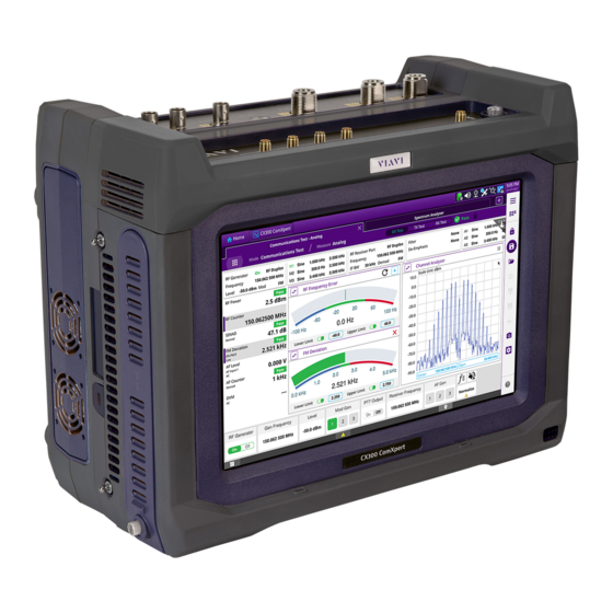
Viavi CX300 ComXpert Operation Manual
Communications service monitor
Hide thumbs
Also See for CX300 ComXpert:
- Manual (48 pages) ,
- Quick start manual (2 pages) ,
- Manual (47 pages)
Table of Contents
Advertisement
Advertisement
Chapters
Table of Contents
Troubleshooting

Related Manuals for Viavi CX300 ComXpert


Summary of Contents for Viavi CX300 ComXpert
- Page 1 CX300 ComXpert Communications Service Monitor Operation Manual...
- Page 2 CX300 ComXpert Communications Service Monitor Operation Manual 22130634 Rev. 001 VIAVI Solutions 1-844-GO-VIAVI www.viavisolutions.com...
- Page 3 Copyright/Trademarks © Copyright 2022 VIAVI Solutions, Inc. All rights reserved. No part of this guide may be reproduced or transmitted, electronically or otherwise, without written permission of the publisher. VIAVI Solutions and the VIAVI logo are trademarks of VIAVI Solutions Inc.
- Page 4 Declaration of Conformity VIAVI recommends keeping a copy of the Declaration of Conformity that shipped with the unit with the test set at all times. Warranty Information Warranty information for this product is available on the VIAVI website at https://www.viavisolutions.com/en-us/warranty-information.
- Page 5 VIAVI has established a take-back processes in compliance with the EU Waste Electrical and Electronic Equipment (WEEE) Directive, 2012/19/EU, and the EU Battery Directive, 2006/66/EC. Instructions for returning waste equipment and batteries to VIAVI can be found in the WEEE section of VIAVI’s Standards and Policies web page.
- Page 6 For the VIAVI position statement on the use of Proposition 65 chemicals in VIAVI products, see the Hazardous Substance Control section of VIAVI’s Standards and Policies web...
- Page 7 CE Compliant CE Label indicates item meets the requirements of the applicable European Directives. Fuse Symbol Indicates a fuse location (AC or DC). 22130634 CX300 ComXpert Operation Manual Rev. 001...
- Page 8 A Lithium-Ion battery is used in this equipment. Lithium is a toxic substance. • Do not crush, incinerate or dispose of in normal waste. • Do not short circuit or force discharge since this might cause the battery to vent, overheat or explode. Rev. 001 CX300 ComXpert Operation Manual 22130634 February, 2022...
- Page 9 Electronic Equipment (WEEE) Directive, 2012/19/EU, and the EU Battery Directive, 2006/66/EC. Information and instructions for returning waste equipment and batteries to VIAVI can be found on the VIAV website in the WEEE section of VIAVI’s Standards and Policies web page at: VIAVI’s Standards and Policies web page.
- Page 10 Contact VIAVI for packaging and labeling instructions. Mise en Garde Cet appareil contient une batterie au lithium-ion et peut nécessiter un emballage spécial et un étiquetage externe lors de l'expédition. Contactez VIAVI pour l'emballage et les instructions étiquetantes. Rev. 001 CX300 ComXpert Operation Manual...
- Page 11 Do not overload input connectors. Refer to product specifications or the product data sheet for maximum input ratings. Mise en Garde Ne surchargez pas les connecteurs d'entrée. Reportez-vous aux spécifications du produit ou à la fiche technique du produit pour connaître les valeurs d'entrée maximales. 22130634 CX300 ComXpert Operation Manual Rev. 001...
- Page 12 • Connectez uniquement l'adaptateur secteur / cordon d'alimentation à la tension secteur appropriée indiquée sur l'étiquette des caractéristiques nominales. • N'utilisez pas l'adaptateur / cordon d'alimentation secteur s'il semble endommagé ou s'il a été modifié. Figure 1 AC Power Adapter Label Rev. 001 CX300 ComXpert Operation Manual 22130634 February, 2022...
- Page 13 électrique. L’énergie résiduelle est dans les limites des exigences de sécurité approuvées. Par contre, un léger choc électrique peut être ressenti si l’on touche les broches de la prise immédiatement après son débranchement. 22130634 CX300 ComXpert Operation Manual Rev. 001...
- Page 14 Battery Safety Information There are two batteries included with the product, and are only to be used with VIAVI CX300 ComXpert. Battery Storage, Handling and Disposal CAUTION • To avoid risk of fire and burns, do not tamper with the batteries.
- Page 15 This device does not contain user serviceable parts. Servicing should only be performed by Qualified Service Personnel. Mise en Garde Cet appareil ne contient pas de pièces pouvant être entretenues par l’utilisateur. L’entretien doit seulement être effectué par du personnel de service qualifié. 22130634 CX300 ComXpert Operation Manual Rev. 001...
- Page 16 • Connect the equipment into an outlet on a circuit different from that to which the receiver is connected. • Use properly shielded and grounded cables and connectors in order to meet FCC emission limits. Rev. 001 CX300 ComXpert Operation Manual 22130634 February, 2022...
- Page 17 Les utilisateurs de cet équipment doivent examiner soigneusement tout fonctionnement provoquant le rayonnement d'un signal (direct ou indirect) et ils doivent prendre les dispositions nécessaires afin d'eviter des problémes potentiels d'interferénces sur les communications. 22130634 CX300 ComXpert Operation Manual Rev. 001...
- Page 18 This page intentionally left blank. Rev. 001 CX300 ComXpert Operation Manual 22130634 February, 2022...
-
Page 19: Table Of Contents
1.1 CX300 ComXpert Overview ........ - Page 20 8.4 Charging the Battery ..........8-5 Rev. 001 CX300 ComXpert Operation Manual 22130634...
- Page 21 8.7 Updating Software ..........8-9 8.8 CX300 ComXpert Self Test Procedure ....... . 8-10 8.9 Troubleshooting Information .
- Page 22 Table of Contents This page intentionally left blank. Rev. 001 CX300 ComXpert Operation Manual 22130634 TOC - iv February, 2022...
- Page 23 Table 2-1 ..CX300 ComXpert Standard Accessories ......
- Page 24 Table 5-35 ..Oscilloscope Settings and Controls....... . . 5-58 Rev. 001 CX300 ComXpert Operation Manual 22130634...
- Page 25 Table 8-2 ..Troubleshooting Guide ......... . 8-11 22130634 CX300 ComXpert Operation Manual Rev. 001...
- Page 26 List of Tables This page intentionally left blank. Rev. 001 CX300 ComXpert Operation Manual 22130634 LOT - iv February, 2022...
- Page 27 Figure 2-4 ..CX300 ComXpert Screen Layout....... .
- Page 28 Figure 8-2 ..Battery Installation Diagram ........8-8 Rev. 001 CX300 ComXpert Operation Manual 22130634...
- Page 29 Contact Information ..........v 22130634 CX300 ComXpert Operation Manual Rev. 001...
- Page 30 Content Overview This manual is composed of the following chapters: Chapter 1: Overview Provides an overview of the CX300 ComXpert’s features and capabilities. Chapter 2: Getting Started: Setup and Operation Provides instructions for installing, controlling and operating the CX300 ComXpert.
- Page 31 Preface Purpose and Scope The purpose of this manual is to help users successfully use the CX300 ComXpert features and capabilities. This manual includes task-based instructions that describe how to install, configure, and operate the CX300 ComXpert. This manual provides instructions for unpacking, setting up, and operating the CX300.
- Page 32 Text users must type exactly as – Restart the applications using the following shown. command: $BASEDIR/startup/npiu_init restart a:\set.exe Type: in the dialog box. References to other Refer to Newton’s Telecom Dictionary. publications Rev. 001 CX300 ComXpert Operation Manual 22130634 Preface - iv February, 2022...
- Page 33 • https://www.viavisolutions.com/en-us/product-category/radio-test/communications- service-monitors Product Nomenclature The terms CX300, CX300 ComXpert and test set are used to refer to the CX300 ComXpert Communications Service Monitor. Contact Information Contact the Technical Assistance Center (TAC) for technical support or with any questions regarding this or other VIAVI products.
- Page 34 Preface This page intentionally left blank. Rev. 001 CX300 ComXpert Operation Manual 22130634 Preface - vi February, 2022...
- Page 35 CX300 ComXpert Overview........
-
Page 36: Chapter 1 Cx300 Comxpert Overview
CX300 ComXpert Overview CX300 ComXpert Overview The CX300 ComXpert is a portable communications test set for use in the Land Mobile Radio, Private Mobile Radio, or Two-Way Communications Industry. The CX300 is capable of performing high power measurements as well as fault finding for antennas, power amplifiers, and interconnects. -
Page 37: Features And Capabilities
CX300 software is a field-upgradeable software which can be updated using a network connection or a USB device. CX300 software also supports field-installed software options. The CX300 ComXpert ships from the factory with the current version of Software (SW) and Firmware (FW) installed on the test set. The System Information screen displays the version of the software and firmware installed on the test set. -
Page 38: Rf Features And Capabilities
(radio, antenna, base station) and locate faults in antennas, power amplifiers, and cables. The following are standard CX300 ComXpert features and functions. Modes of operation include Communications Test, Spectrum Analyzer, and Auto-Test. Refer to the CX300 ComXpert data sheet for a complete list of available options. -
Page 39: Controls And Connectors
Chapter 1 CX300 ComXpert Overview Controls and Connectors Controls and Connectors This section describes the CX300’s controls and connectors. See product specifications for complete performance specifications and input/output ratings. CAUTION Do not overload input connectors. Refer to product specifications or the product data sheet for maximum input ratings. - Page 40 Chapter 1 CX300 ComXpert Overview Controls and Connectors Table 1-1 CX300 Top Panel Controls and Connectors Connector Description The AF Input 1 High connector is a high AF Input 1 High Connector audio input differential power connector used for receiving high power signals.
- Page 41 Chapter 1 CX300 ComXpert Overview Controls and Connectors Table 1-1 CX300 Top Panel Controls and Connectors (Continued) Connector Description The Trigger Output connector is an SMA Trigger Output Connector type-F connector that sends 1 PPS clock or 10 ms synchronization signals from an internal timing reference.
-
Page 42: Table 1-1
Chapter 1 CX300 ComXpert Overview Controls and Connectors Table 1-1 CX300 Top Panel Controls and Connectors (Continued) Connector Description The Audio connector is a 3.5 mm size mono Audio Connector jack that supports the use of headphones; connecting a headset that contains an integrated microphone turns off the CX300 internal speaker. - Page 43 Chapter 1 CX300 ComXpert Overview Controls and Connectors 1.4.1.1 POWER BUTTON/LED The Power Button/LED use different colors to indicate the test set’s operational status, battery, and AC Power usage. Table 1-2 Power Button/LED - Status LED Color Indicates • Unit is OFF Not Illuminated •...
-
Page 44: Side Panel Controls And Connectors
Chapter 1 CX300 ComXpert Overview Controls and Connectors 1.4.2 Side Panel Controls and Connectors Figure 1-3 CX300 Side Panel Controls and Connectors Table 1-3 CX300 Side Panel Controls and Connectors Idx# Connector /Controls Description The Micro SD Port allows a Micro SD card to be Micro SD Port used as storage location for instrument data. - Page 45 Chapter 1 CX300 ComXpert Overview Controls and Connectors Table 1-3 CX300 Side Panel Controls and Connectors (Continued) Idx# Connector /Controls Description The Reset button is a recessed button that is Reset Button used to restore the device to known IP settings.
- Page 46 Chapter 1 CX300 ComXpert Overview Controls and Connectors This page intentionally left blank. Rev. 001 CX300 ComXpert Operation Manual 22130634 1 - 12 February, 2022...
- Page 47 CX300 ComXpert Screens........
-
Page 48: Chapter 2 Getting Started: Setup And Operation
Chapter 2 Getting Started: Setup and Operation Upon Receipt Upon Receipt This section describes tasks that should be completed when a CX300 ComXpert is received from the factory. 2.1.1 Unpacking Equipment VIAVI instruments are shipped using anti-static packing material to stabilize the components inside the shipping container. -
Page 49: Upon Receipt
2.1.4 Verifying Shipment Contents Verify the shipment is complete according to the items listed on the packing list. Accessories may be shipped in a separate box. Report any discrepancies to VIAVI. 2.1.4.1 Standard Hardware Accessories The following items are included with the CX300 ComXpert:... -
Page 50: Powering The Test Set
Powering the Test Set 2.1.4.2 Recommended Optional Accessories The following are optional accessories that VIAVI recommends purchasing for the CX300 ComXpert. Refer to the product data sheet for a complete list of available optional accessories. Table 2-2 Recommended Optional Accessories... -
Page 51: Ac Power Operation
Improper grounding of equipment can result in electrical shock. To ensure proper grounding, this device should only be connected to a grounded AC Power Supply. To Install the Battery See section 8.5, “Battery Replacement”, on page 8-6 for the battery installation procedure. 22130634 CX300 ComXpert Operation Manual Rev. 001... -
Page 52: Turning The Test Set On
Power Options screen to power down the test set. Wait while the test set performs a series of reboot processes. Do not interrupt the power-down process or unsaved information may be lost. Rev. 001 CX300 ComXpert Operation Manual 22130634 2 - 6 February, 2022... -
Page 53: Verify Test Set Operation
Verify Test Set Operation The CX300 ComXpert has an automated Built-in-Test (BIT) procedure. The BIT is referred to as a Self Test. The CX300’s Self Test evaluates the general functionality of the test set’s generate and receive function, instruments and switches to ensure the device is operating properly. -
Page 54: Cx300 Comxpert Screens
Chapter 2 Getting Started: Setup and Operation CX300 ComXpert Screens CX300 ComXpert Screens The Home button and CX300 ComXpert button are used to switch between system screens and test and measurement screens. System screens contain controls and settings for system functions like network connectivity, system upgrades, timing reference, and power management, etc. - Page 55 The CX300 ComXpert screen is accessible using the following method: • Press the CX300 ComXpert button on the Device Toolbar. Select a control from the CX300 ComXpert screen for desired Test and Measurement Screens, or Mode Measurement Screens. The CX300 ComXpert screen contains the controls and settings for the desired Test and Measurement Screens, for performing Test and Measurements.
-
Page 56: Ui Navigation, Control And Layout
When the CX300 is powered on the Home screen is displayed. See Figure 2-3. The Home screen contains collapsible menus that expand to provide access to the system and test functions that are available on the device. Rev. 001 CX300 ComXpert Operation Manual 22130634 2 - 10 February, 2022... -
Page 57: Screen Layout
User Interface (UI). The general framework of the UI consists of the following areas: • Device Toolbar (page 2-12) • Main Display Area (page 2-14) • Status Bar (page 2-15) 22130634 CX300 ComXpert Operation Manual Rev. 001... -
Page 58: Table 2-3
Screen Layout Device Toolbar Main Display Area Status Bar CX300 ComXpert Screen Layout Figure 2-4 2.7.1 Device Toolbar The Device Toolbar contains controls that are used to access CX300 system, test, and measurement screens. Some of the controls are also used to indicate test set status and active functions. - Page 59 Screen Layout Table 2-3 Device Toolbar Controls and Indicators (Continued) Button Name Description The CX300 ComXpert button accesses CX300 CX300 ComXpert test and measurement functions. When this Button button is pressed, the UI updates to the last viewed test and measurement screen, or mode measurement screen.
- Page 60 Screens”, provides descriptions of all system functions and system screen controls and settings. • Chapter 5 “Test and Measurement Functions”, provides descriptions of standard CX300 test and measurement functions. Rev. 001 CX300 ComXpert Operation Manual 22130634 2 - 14 February, 2022...
-
Page 61: Operating And Navigating The User Interface
2.8.1 Selecting System and Test Screens The Home button and CX300 ComXpert button are used to switch between system screens and test and measurement screens. • These buttons are located on the left side of the Device Toolbar, at the top of the... -
Page 62: Selecting And Entering Parameters
Numeric Keypad. • See section 2.8.2.3.2, “Numeric Slider”, on page 2-18 for a description of the controls on the Numeric Slider. Rev. 001 CX300 ComXpert Operation Manual 22130634 2 - 16 February, 2022... - Page 63 Pressing this button increases the parameter by Step Increase the value in the Step field. The Step field defines the increment value by Step Field which a parameter is decreased or increased when the buttons are pressed. 22130634 CX300 ComXpert Operation Manual Rev. 001...
- Page 64 Once the digit range is selected, the value is increased or decreased by dragging the Slider Bar or pressing the Increment Up and Decrement Down arrows. Values are active at the time that they are being changed. Rev. 001 CX300 ComXpert Operation Manual 22130634 2 - 18 February, 2022...
- Page 65 Decrement Down time the button is pressed. Buttons The Decrement Down button decreases the last digit selected in the bounding box by one each time the button is pressed. 22130634 CX300 ComXpert Operation Manual Rev. 001...
- Page 66 The Close Keyboard button closes the UI Close Keyboard keyboard. Any un-entered changes are lost Button when the keyboard is closed. Rev. 001 CX300 ComXpert Operation Manual 22130634 2 - 20 February, 2022...
-
Page 67: Chapter 3 System Settings Screens
Web Browser Screen ......... . . 3-26 NOTE Chapter 4 “Configuring System Settings” for step-by-step instructions to configure various system settings. 22130634 CX300 ComXpert Operation Manual Rev. 001... -
Page 68: System Settings Screens
This button is enabled when using the Copy function (see Paste Button “Copy / Paste Button” description in Table 3-2 on page 3-3). This menu is used to select and de-select files and Select Menu directories. Rev. 001 CX300 ComXpert Operation Manual 22130634 3 - 2 February, 2022... -
Page 69: Removable Storage Screen
USB device or SD card. File storage location is defined as part of the file save procedure. See section 7.1.1, “Saving Files”, on page 7-2 for more information. Removable Storage Button 22130634 CX300 ComXpert Operation Manual Rev. 001... -
Page 70: Bluetooth® Screen
When a scan is performed, this area of the screen is populated Discovered with a list of Bluetooth enabled devices that are within range of Devices the CX300. Rev. 001 CX300 ComXpert Operation Manual 22130634 3 - 4 February, 2022... -
Page 71: Network Screen
Network screen. The test set can be configured to obtain all IPv4 parameters from a DHCP (Dynamic Host Configuration Profile) server, or configured to use a user-defined Static IP Address. IPv6 is also supported. 22130634 CX300 ComXpert Operation Manual Rev. 001... - Page 72 • Enter the address for the gateway that is used to route packets that are not on the same subnet. IPv4 DNS Server • Enter the address of the DNS server. Rev. 001 CX300 ComXpert Operation Manual 22130634 3 - 6 February, 2022...
- Page 73 (VLAN ID) which is a number between 0 and 4095. When the VLAN check box is enabled, the CX300 can be connected to a VLAN. The VLAN ID field defines the VLAN ID assigned to the CX300. 22130634 CX300 ComXpert Operation Manual Rev. 001...
- Page 74 The CX300’s Certificate tab is used to manage the test set’s digital certificates. Rev. 001 CX300 ComXpert Operation Manual 22130634 3 - 8 February, 2022...
-
Page 75: Power Management Screen
Battery Power Saving Mode The test set is equipped with a battery power-saving mode that is enabled by selecting the Enable auto-off while on battery check box. Figure 3-3 Power Management Screen Power Management Button 22130634 CX300 ComXpert Operation Manual Rev. 001... - Page 76 44°C. Provides the user helpful info related to each Battery Info battery, including Charge Level (%), the Manufacturer, and the Serial Number. Rev. 001 CX300 ComXpert Operation Manual 22130634 3 - 10 February, 2022...
- Page 77 • Not connected to an AC Power supply (no plug icon) • Running on battery power • Green fill level indicates battery charge remaining. Indicates the following: • No Battery installed (battery grayed out) • Connected to an AC Power supply (plug icon) 22130634 CX300 ComXpert Operation Manual Rev. 001...
-
Page 78: Date And Time Screen
See section 4.3, “Setting Date and Time”, on page 4-4 for more information about setting the date and time. Figure 3-4 Date and Time Settings - Manual Settings Figure 3-5 Date and Time Settings - NTP Server Rev. 001 CX300 ComXpert Operation Manual 22130634 3 - 12 February, 2022... - Page 79 Set clock automatically check box is selected. Calendar Controls The calendar controls are used to manually set the test set’s date. These controls are not active when the Set clock automatically check box is selected. 22130634 CX300 ComXpert Operation Manual Rev. 001...
-
Page 80: Table 3-10
Figure 3-6 Display Settings The Display screen contains the following controls and settings: Table 3-10 Display Controls and Settings Control/Setting Description Display Button Adjusts the intensity of the display. Brightness Rev. 001 CX300 ComXpert Operation Manual 22130634 3 - 14 February, 2022... -
Page 81: Remote Screen
The test set’s remote default settings are “OFF”; restoring the test set to factory default settings will terminate all remote connections. Remote connectivity cannot be re-established until the test set is reconfigured locally to enable remote access. Figure 3-7 Remote Controls and Settings 22130634 CX300 ComXpert Operation Manual Rev. 001... -
Page 82: Table 3-11
4.9.6, “Transferring Files with Smart Access”, on page 4-21 for information. See section 4.9, “Using Smart Access Anywhere”, on page 4-16 for detailed instructions for installing and using the Smart Access Anywhere utility. Rev. 001 CX300 ComXpert Operation Manual 22130634 3 - 16 February, 2022... -
Page 83: Upgrade Screen
This section describes the top-level controls and prompts that users encounter when upgrading the CX300 located on the Upgrade screen, and are described as part of the software update. See section 4.12, “Updating the System Software”, on page 4-24 information. Figure 3-8 Upgrade Screen 22130634 CX300 ComXpert Operation Manual Rev. 001... -
Page 84: Table 3-12
When locked, a password is required to access the test set. This function is useful when using the test set remotely to prevent local users from inadvertently interrupting a test. Test Set Lock Button Rev. 001 CX300 ComXpert Operation Manual 22130634 3 - 18 February, 2022... -
Page 85: Audio Screen
NOTE When selecting an external clock source, ensure that the clock source is connected to the unit and the external clock source is accurate to within +/- 500 ppb. Clock Source Button 22130634 CX300 ComXpert Operation Manual Rev. 001... -
Page 86: Table 3-13
The GNSS screen is used to configure the CX300 GNSS settings to use satellites to determine location, or to use GNSS as a frequency and clock source. GNSS Button Rev. 001 CX300 ComXpert Operation Manual 22130634 3 - 20 February, 2022... -
Page 87: Table 3-14
When GPS has obtained correct position information, the GPS Indicator is displayed in the Device Status Bar. NOTE The GPS lock icon indicator for Lock Status is available only while GNSS is set to On. 22130634 CX300 ComXpert Operation Manual Rev. 001... -
Page 88: Table 3-15
Continuously calculates positioning for continuous location information. Auto Calculates positioning until accurate location information is determined. Switches to fixed position using accurate location information and switches to determine timing accuracy. Rev. 001 CX300 ComXpert Operation Manual 22130634 3 - 22 February, 2022... -
Page 89: System Info Screen
NOTE The default Antenna Time Bias value is 28, which is the optimal value for the VIAVI qualified antenna. If you are using a different antenna, determine the optimal bias value by referring to the vendor specifications for the antenna (and if applicable, splitter or amplifier), then specify the bias value in nanoseconds. -
Page 90: Table 3-16
Chapter 3 System Settings Screens System Settings Screens The following data is key product information which may be required when updating the test set, or when contacting VIAVI for technical support: Table 3-16 System Information System Information Description CX300 Serial Number ComXpert platform serial number. -
Page 91: Table 3-18
To ensure the test set has the latest configuration settings, software options, updates, and ownership registration information, the CX300 should be synchronized with a VIAVI server when it is received from the factory, and on a routine basis thereafter. -
Page 92: Table 3-19
Accesses recently downloaded files. Downloaded files can also View Downloads be accessed from the System > Files screen. The Zoom In and Zoom Out buttons adjust screen image Zoom In/Out size. Rev. 001 CX300 ComXpert Operation Manual 22130634 3 - 26 February, 2022... - Page 93 This button is used to close the Web browser screen. When Close Button the Web browser screen is closed, the Web Browser button is removed from the Device Toolbar. 22130634 CX300 ComXpert Operation Manual Rev. 001...
- Page 94 Chapter 3 System Settings Screens System Settings Screens This page intentionally left blank. Rev. 001 CX300 ComXpert Operation Manual 22130634 3 - 28 February, 2022...
-
Page 95: Chapter 4 Configuring System Settings
Capturing a Screen Shot ......... . . 4-30 NOTE Chapter 3 “System Settings Screens”, for detailed information about system functions. 22130634 CX300 ComXpert Operation Manual Rev. 001... -
Page 96: Configure Battery Saving Mode
• When the test set is on battery mode, it is normal for the screen to dim. • Changes do not affect brightness of a remote connection to the device. Rev. 001 CX300 ComXpert Operation Manual 22130634 4 - 2... - Page 97 If a screen saver is activated, and the password is lost or forgotten, the test set will have to be re-imaged to restore the test set to operating condition. See section 4.14, “Re-imaging the System”, on page 4-29 for instructions. 22130634 CX300 ComXpert Operation Manual Rev. 001...
-
Page 98: Setting Date And Time
The following procedure describes how to set the date and time. Proceed to the Date and Time screen. Use 24-hour time Select the check box to display the time in HH:MM:SS format. Rev. 001 CX300 ComXpert Operation Manual 22130634 4 - 4 February, 2022... -
Page 99: Establishing A Network Connection
Enable Network Connectivity Network connectivity must be enabled in order to establish a connection to an Ethernet or WiFi network. To Enable Network Connectivity Go to the System Screen. Select the Network button. 22130634 CX300 ComXpert Operation Manual Rev. 001... - Page 100 Mode Settings”, on page 4-8 When all settings have been configured, select the Network On/Off soft-key to enable network connectivity. The device establishes an Ethernet connection to the LAN. Rev. 001 CX300 ComXpert Operation Manual 22130634 4 - 6 February, 2022...
- Page 101 Share the IP from another interface (for multi Shared interface mode). When all settings have been configured, select the Network On/Off soft-key to enable network connectivity. The device establishes an Ethernet connection to the LAN. 22130634 CX300 ComXpert Operation Manual Rev. 001...
- Page 102 Enter the address of the DNS server. When all settings have been configured, select the Network ON/Off soft-key to enable network connectivity. The device establishes an ethernet connection to the LAN. Rev. 001 CX300 ComXpert Operation Manual 22130634 4 - 8 February, 2022...
- Page 103 Setting Value The SSID (Service Set Identifier) of the WiFi network. SSID The password required to authenticate to the network. Password A password is not required if Key Management is set to None. 22130634 CX300 ComXpert Operation Manual Rev. 001...
- Page 104 Navigate to the Network panel (System button > Network button). Select the WiFi button located on the soft-key panel. The device automatically scans for WiFi networks and lists each network with the following status: Rev. 001 CX300 ComXpert Operation Manual 22130634 4 - 10 February, 2022...
- Page 105 The status of the connection (Network Up) and details concerning the connection (IP address, netmask, gateway, and DNS server) appear at the top right of the menu. The device is connected to the WiFi network. 22130634 CX300 ComXpert Operation Manual Rev. 001...
-
Page 106: Setting Up Gnss
(C/No) for the satellite signals that will be used by the GNSS receiver. NOTE Using satellites with a weak C/No might degrade performance. In the Antenna Time Bias field, specify the optimal value. Rev. 001 CX300 ComXpert Operation Manual 22130634 4 - 12 February, 2022... - Page 107 3D form (DXDYDZ) to a change in Latitude, change in Longitude, and change in Ellipsoidal Height. • Lock Status is indicated by the GPS Indicator button. See section 3.1.14.1, “GNSS Lock Status”, on page 3-21). 22130634 CX300 ComXpert Operation Manual Rev. 001...
-
Page 108: Configuring Timing Reference (Clock Source)
See section 4.5, “Setting up GNSS”, on page 4-12). Navigate to the Clock Source screen. from the Clock Source menu. Select The Clock Source Indicator updates to identify the selected clock source. Rev. 001 CX300 ComXpert Operation Manual 22130634 4 - 14 February, 2022... -
Page 109: Remotely Operating The Test Set
4.7.2 Remote Programming Commands The CX300 can be controlled over a network connection using remote programming commands. Refer to the CX300 ComXpert Remote Programming Manual 22146776 for information and instructions. Setting up a Bluetooth® Connection The following procedures describes how to set up Bluetooth Connection. -
Page 110: Using Smart Access Anywhere
Download Utility to an iOS or Android Device The following procedure describes how to download utility to an iOS or device. Proceed to the Apple Store or Google Play to download and install the utility. Rev. 001 CX300 ComXpert Operation Manual 22130634 4 - 16 February, 2022... - Page 111 (if a proxy is used). Figure 4-1 Wired Ethernet Connection Diagram 4.9.3.2 WiFi Connection Figure 4-2 illustrates a CX300 connected to a workstation using a WiFi connection. Figure 4-2 WiFi Connection Diagram 22130634 CX300 ComXpert Operation Manual Rev. 001...
- Page 112 • Launch the utility on the CX300 to obtain the required remote access code. • Launch the utility on your PC or mobile device, then enter the remote access code that was obtained from the CX300. Rev. 001 CX300 ComXpert Operation Manual 22130634 4 - 18 February, 2022...
- Page 113 • Press the Clear test results button to delete the current table, and retest the connection if desired. • If connection is deemed to be valid, enter the access code and establish connection. 22130634 CX300 ComXpert Operation Manual Rev. 001...
- Page 114 The Smart Access Anywhere screen appears. NOTE After upgrading or rebooting a remote CX300, please wait at least two minutes before re-establishing the link between your workstation and the device. Rev. 001 CX300 ComXpert Operation Manual 22130634 4 - 20 February, 2022...
- Page 115 After the transfer is complete, the message disappears and the transferred file is underlined in the workstation or instrument’s file manager. NOTE Files cannot be transferred in multiples; files must be transferred one at a time. 22130634 CX300 ComXpert Operation Manual Rev. 001...
-
Page 116: Managing System Information
The Internet proxy configuration is available exclusively if the port selected is Alternative port (443) and if HTTPS packing is selected. NOTE If the default parameters need to be modified, VIAVI recommends you discuss it with your local network administrator. After configuring the settings, select Back to main page. -
Page 117: Managing Options
The following procedures describe how to enable, review, and purchase software options. 4.11.1 Enabling Software Options Software options may be available on the unit or purchased separately. For information about purchasing software options, contact the VIAVI Solutions Sales Office for your region. See section 3.1.15, “System Info Screen”, on page 3-23 for details about option information provided on the System Info screen. -
Page 118: Updating The System Software
Download the system software to a computer, then extract software files to a USB drive. VIAVI recommends that the USB drive have no other content stored on it. The update process when using a USB drive involves the following procedures: •... - Page 119 Press the OK button to proceed with the software update. Do not disconnect the USB device from the test set during the update. The test set automatically restarts when the update is completed. After the test set has restarted, disconnect the USB device. 22130634 CX300 ComXpert Operation Manual Rev. 001...
- Page 120 Click Extract to initiate extraction of the system software files to the network directory. When all files have been extracted, proceed to "Performing the USB Software Update" on page 4-25. Rev. 001 CX300 ComXpert Operation Manual 22130634 4 - 26 February, 2022...
- Page 121 • A dialog box appears with prompts to either exit all tests that are running or cancel the update if the tests cannot be stopped. • The test set automatically restarts when the update is completed. After the test set has restarted, disconnect the USB device. 22130634 CX300 ComXpert Operation Manual Rev. 001...
-
Page 122: Synchronizing To The Stratasync™ Server
4.13 Synchronizing to the StrataSync™ Server To automatically obtain the latest configuration settings, software options, updates and ownership registration information, the unit should be synchronized with a VIAVI server via the Internet using an optional subscription-based service called StrataSync™. In addition to the latest operating software, synchronization also uploads user files saved on the unit to the StrataSync™... -
Page 123: Re-Imaging The System
• The re-imaging process starts. Do not unplug the USB drive from the unit. • The unit automatically restarts when the update is completed. After the unit has restarted, unplug the USB drive. 22130634 CX300 ComXpert Operation Manual Rev. 001... -
Page 124: Capturing A Screen Shot
The PNG file is saved to the internal file manager. NOTE The images can be viewed on the test set through the Folder Button on the Test Controls Toolbar. Folder Button Rev. 001 CX300 ComXpert Operation Manual 22130634 4 - 30 February, 2022... -
Page 125: Chapter 5 Test And Measurement Functions
Navigation Diagrams ..........5-75 ‘ NOTE Analog measurement functions are standard CX300 measurements. Optional measurements, such as P25, are described in option specific manuals. 22130634 CX300 ComXpert Operation Manual Rev. 001... -
Page 126: Test Modes And Measurements
See section 5.16, “AutoTest Mode”, on page 5-71 for a description of Auto-Test. Rev. 001 CX300 ComXpert Operation Manual 22130634 5 - 2 February, 2022... -
Page 127: Overview Of Test And Measurement Screens
To Display the Test Home Screen • From a test screen, press the Home button. • From a system screen, select the CX300 ComXpert button, then press the Home button. The layout of the Test Home Screen will resemble the example shown in Figure 5-1. - Page 128 The Done button confirms the selection and loads the selected mode of operation. 5.2.2 Screen Navigation Diagrams See section 5.17, “Navigation Diagrams”, on page 5-75 for how to navigate and access test functions, controls, and settings. Rev. 001 CX300 ComXpert Operation Manual 22130634 5 - 4 February, 2022...
- Page 129 The UI updates to display the test screen as it was configured during the last user session for the selected mode of operation. Test Screens are divided into the following areas: Figure 5-2 Example of Test and Measurement Main Screen 22130634 CX300 ComXpert Operation Manual Rev. 001...
- Page 130 See “Navigation Diagrams”. These buttons are used to select the meter or graph that Measurement is displayed on the Measurement Panes. See Buttons “Navigation Diagrams”. Rev. 001 CX300 ComXpert Operation Manual 22130634 5 - 6 February, 2022...
- Page 131 See section 7.1.5, “Loading Files”, on page 7-4 information. When the Auto Scale button is selected the system Auto Scale sets the plot scales to a setting appropriate to the Button characteristics identified in the received signal. 22130634 CX300 ComXpert Operation Manual Rev. 001...
- Page 132 See section 7.1.1, “Saving Files”, on page 7-2 additional information about saving screens. This is a quick-access button that allows access to System System Information and System Settings. Settings Button Rev. 001 CX300 ComXpert Operation Manual 22130634 5 - 8 February, 2022...
- Page 133 Test Functions Toolbar. The following controls and settings are located in the Marker Controls Toolbar: Marker Slider Position and Reading Marker View Reading Type Marker to Navigation Frequency Buttons Figure 5-3 Marker Controls Toolbar 22130634 CX300 ComXpert Operation Manual Rev. 001...
- Page 134 • The marker’s X and Y values display the difference compared with the Delta marker. • The Marker label updates to “D#” to indicate delta measurement is selected. Rev. 001 CX300 ComXpert Operation Manual 22130634 5 - 10 February, 2022...
- Page 135 Right Peak current position. When the Always Peak is set to On, the instrument moves the Always Peak active marker automatically to the highest peak of the trace every time the trace is refreshed. 22130634 CX300 ComXpert Operation Manual Rev. 001...
- Page 136 Type Displays the measurement position. "Marker Marker Position Position" on page 5-10 "To Position a Marker" on page 5-13. Displays the reading at the marker’s position. Marker Reading Rev. 001 CX300 ComXpert Operation Manual 22130634 5 - 12 February, 2022...
- Page 137 Use the Marker Position field or one of the Marker Navigation buttons to move the selected marker. To Create Delta Measurements Add a marker to the plot field. Press the Delta or Delta Pair Button. 22130634 CX300 ComXpert Operation Manual Rev. 001...
-
Page 138: Accessing Test Controls And Settings
Method 3 - Test Settings Block Press the Test Setting Block from the Parameter Toolbar to open the Test Settings menu. Select the desired control or setting. Configure the parameter as desired. Rev. 001 CX300 ComXpert Operation Manual 22130634 5 - 14 February, 2022... -
Page 139: Cx300 Generators
RF Generator. The RF Generator frequency should be set according to the following: • The test being performed. • The frequency range of the receiver. The Enable toggle switch turns the RF Generator output ON Enable and OFF. 22130634 CX300 ComXpert Operation Manual Rev. 001... - Page 140 Define the RF Generator Level. If desired, define the RF Generator Level Offset. Set the RF Generator Enable toggle switch to ON. The CX300 is now generating an RF signal. Rev. 001 CX300 ComXpert Operation Manual 22130634 5 - 16 February, 2022...
- Page 141 This menu selects the CX300 input connector to which the Mod Ext Source external modulation source is connected. A modulation source must be connected to the selected input connector to obtain a modulated input signal. 22130634 CX300 ComXpert Operation Manual Rev. 001...
- Page 142 When Modulation Generator is selected as the signal source for tone encoding, Modulation Generators 1 and 2 are not available. See section 5.10, “Tone Encoding”, on page 5-45 for information. Rev. 001 CX300 ComXpert Operation Manual 22130634 5 - 18 February, 2022...
- Page 143 This field defines to output level of the signal in either AF Gen Level Voltage peak-to-peak (Vpp) or Volts Root Mean Square (Vrms) as selected in the Level Type field. 22130634 CX300 ComXpert Operation Manual Rev. 001...
- Page 144 Define the AF Generator Frequency. Define the AF Generator Level. Set the AF Generator Enable toggle switch to ON. The CX300 is now generating an audio signal at the AF Output connector. Rev. 001 CX300 ComXpert Operation Manual 22130634 5 - 20 February, 2022...
-
Page 145: Cx300 Receive Functions
Toolbar. The parameters of the modulation type of the incoming signal are configured on the Analog Demod settings menu. INPUT OVERLOAD Do not overload input connectors. Refer to product labeling or product specifications for maximum input ratings. 22130634 CX300 ComXpert Operation Manual Rev. 001... -
Page 146: Table 5-10
Frequency (IF) narrow band transmitters, therefore, select the IF bandwidth Bandwidth (BW) appropriate for the characteristics of the incoming signal. Rev. 001 CX300 ComXpert Operation Manual 22130634 5 - 22 February, 2022... - Page 147 (ON) in the input signal path. The pre-amplifier (PreAmp) is typically used to boost weak incoming signals to eliminate noise and produce a clean signal that is strong enough to be processed. 22130634 CX300 ComXpert Operation Manual Rev. 001...
- Page 148 Select an RF Receiver IF Bandwidth. Set Level Control Mode to Auto. 10. Navigate to the Analog Demod settings. Select the Demod Type according to the modulation of the incoming signal. Rev. 001 CX300 ComXpert Operation Manual 22130634 5 - 24 February, 2022...
-
Page 149: Table 5-11
FGEN Loop back When FGEN Loop back is selected the CX300 uses the internal AF Generator signal as the Audio In signal source. 22130634 CX300 ComXpert Operation Manual Rev. 001... - Page 150 Not applicable to Psophometric filter type. Selects the input impedance of the Audio In connector to a Audio 1 value that matches the output impedance of the audio source. Impedance Rev. 001 CX300 ComXpert Operation Manual 22130634 5 - 26 February, 2022...
-
Page 151: Cx300 Meters
Table 5-12 on page 5-28 Figure 5-6 on page 5-30 provide information and descriptions of the various indicators a user may encounter when using meter limits. 22130634 CX300 ComXpert Operation Manual Rev. 001... - Page 152 Figure 5-5 Limit Check Indicators - Example of Invalid State Pass/fail indicators are displayed in the meter reading pane and Pass/Fail Text in the Title Bar to provide visual indicators of measurement Indicators pass/fail status. Rev. 001 CX300 ComXpert Operation Manual 22130634 5 - 28 February, 2022...
- Page 153 Measurement to indicate pass/fail status. • Blue indicates the measurement is below the lower limit • Red indicates the measurement is above the upper limit • Green indicates the measurement passes defined limits 22130634 CX300 ComXpert Operation Manual Rev. 001...
- Page 154 Chapter 5 Test and Measurement Functions CX300 Meters Figure 5-6 Limit Check Indicators Rev. 001 CX300 ComXpert Operation Manual 22130634 5 - 30 February, 2022...
- Page 155 ). The following are examples of when meters should be refreshed: • When limits have been triggered and a new measurement is started. • To restart average measurement calculations. • When test parameters have been changed. 22130634 CX300 ComXpert Operation Manual Rev. 001...
-
Page 156: Table 5-13
The Single Sideband (SSB) Depth meter displays the percentage of modulation of an SSB modulated signal. The SSB Depth meter is displayed when the Analog Demodulation Type is set to SSB (see Table 5-13 on page 5-33). Rev. 001 CX300 ComXpert Operation Manual 22130634 5 - 32 February, 2022... - Page 157 Minimum When Min is selected, the meter displays the lowest reading detected at that point in time. The meter updates when/if a reading is detected that is lower than the currently displayed measurement. 22130634 CX300 ComXpert Operation Manual Rev. 001...
- Page 158 The De-Emphasis filter must match the pre-emphasis value applied at the transmitter in order to obtain accurate measurements. Rev. 001 CX300 ComXpert Operation Manual 22130634 5 - 34 February, 2022...
-
Page 159: Table 5-14
5.6.3, on page 5-31. • A positive error indicates that the transmitter signal’s frequency is too high. • A negative error indicates that the transmitter signal’s frequency is too low. 22130634 CX300 ComXpert Operation Manual Rev. 001... -
Page 160: Table 5-15
This field sets the notch filter bandwidth used when performing Notch BW noise measurements. This field defines the frequency that is being measured when Notch Frequency performing noise measurements. Rev. 001 CX300 ComXpert Operation Manual 22130634 5 - 36 February, 2022... -
Page 161: Table 5-16
SNR Hum & Noise is a measurement of the level of the audio signal that is demodulated by the test set when the radio sends a modulated signal, versus when the signal is not modulated. 22130634 CX300 ComXpert Operation Manual Rev. 001... - Page 162 Audio Noise meter controls and settings are accessed from the Noise (Audio) settings menu. Audio Noise meter signal routing is configured on the Audio Controls Window (see See section 5.7, “Audio Controls and Signal Routing”, on page 5-42). Rev. 001 CX300 ComXpert Operation Manual 22130634 5 - 38 February, 2022...
-
Page 163: Table 5-18
Table 5-19 Audio Distortion Meter Controls and Settings Parameter Description This field sets the notch filter bandwidth used when performing Notch BW noise measurements. This field defines the frequency that is being measured when Notch Frequency performing noise measurements. 22130634 CX300 ComXpert Operation Manual Rev. 001... -
Page 164: Table 5-20
Notch Enable and Noise & SNR Measurements. When Hum & Noise SNR Notch Filter Mode is enabled, the notch filter removes the sub audible CTCSS or CDCSS tone. Rev. 001 CX300 ComXpert Operation Manual 22130634 5 - 40 February, 2022... - Page 165 The AF Audio Counter supports limits which are described in section 5.6.1, on page 5-27, user-configurable meter scales which are described in section 5.6.2, on page 5-31, and average measurements which are described in section 5.6.3, on page 5-31. 22130634 CX300 ComXpert Operation Manual Rev. 001...
-
Page 166: Audio Controls And Signal Routing
See section 5.5.1, “RF Receiver”, on page 5-21. AF Gen When AF Gen is selected the test set routes the signal being generated by the test set’s internal AF Generator to the speaker. Rev. 001 CX300 ComXpert Operation Manual 22130634 5 - 42 February, 2022... -
Page 167: Dvm (Digital Voltmeter)
Peak Positive Peak When Positive Peak is selected, the meter displays the highest positive value measured. Negative Peak When Negative Peak is selected, the meter displays the lowest negative value measured. 22130634 CX300 ComXpert Operation Manual Rev. 001... -
Page 168: Tone Decoding
This parameter applies to Tone Sequential Decode Type. Tone Sequence Protocol This setting selects the type of protocol that is expected in the received Tone Sequential signal. Clears decoded data from Tone Decode screen. Clear Rev. 001 CX300 ComXpert Operation Manual 22130634 5 - 44 February, 2022... -
Page 169: Tone Encoding
AF Output connector. Audio Tone Encoding controls and settings are accessed from the Tone Encoding window or from the Tone Encoding (Audio) settings menu. 22130634 CX300 ComXpert Operation Manual Rev. 001... -
Page 170: Table 5-26
When Live is selected, and when the DTMF Sequence field is selected, a keypad is displayed on the UI to manually enter tones. Each time a digit/symbol is entered into the keypad, that digit/symbol is generated. Rev. 001 CX300 ComXpert Operation Manual 22130634 5 - 46 February, 2022... -
Page 171: Table 5-27
The field defines/indicates the DCS codeword of the generated DCS Code signal. This field defines the level of the encoded tone; CTCSS DCS Level encoder levels are usually set for 15% of system deviation. 22130634 CX300 ComXpert Operation Manual Rev. 001... -
Page 172: Table 5-28
Tone Level component. This field defines the length of time each Tone Remote Tone Duration component is emitted. This button begins sending the defined tone sequence. Start Button Rev. 001 CX300 ComXpert Operation Manual 22130634 5 - 48 February, 2022... -
Page 173: Table 5-30
This field defines the Tone 1 and Tone 2 frequency for the Tone Frequency generator. This field defines the length of time Tone 1 and Tone 2 are Tone Duration emitted. This button begins sending the defined tone sequence. Start Button 22130634 CX300 ComXpert Operation Manual Rev. 001... - Page 174 Navigate to the Tone Encoding (Demod) controls and settings. Select the desired Encoding Type. Configure encoding parameters for the selected type. Refer to the appropriate encoding parameters at the beginning of this section. Rev. 001 CX300 ComXpert Operation Manual 22130634 5 - 50 February, 2022...
-
Page 175: Normalize
Table 5-32 Normalize Controls and Settings Parameter Description Runs across all frequencies. Full Runs for a specific frequency. Spot Runs the normalize procedure selected, either a Full or Start Spot. Clears out the normalize factors of compensation. Erase 22130634 CX300 ComXpert Operation Manual Rev. 001... -
Page 176: Frequency List
Set Button On/Off state of the RF generator Generator State Text Format: On or Off. Output level to which RF Generator will be set. Generator Level UOM: dBm Rev. 001 CX300 ComXpert Operation Manual 22130634 5 - 52 February, 2022... -
Page 177: Channel Analyzer
When Auto is selected, the system sets RBW to a value appropriate for the signal type. Manual When Manual is selected, RBW can be set manually by selecting a pre-defined value from the RBW menu. 22130634 CX300 ComXpert Operation Manual Rev. 001... - Page 178 The Triangle window shapes the signal so that the main lobe is twice as wide as the length of the signal without windowing, and the first side lobe twice as far down as the signal without windowing. Rev. 001 CX300 ComXpert Operation Manual 22130634 5 - 54 February, 2022...
- Page 179 A maximum of 100 times of averaging can be set. Selects active trace to be represented on the analyzer. Select Trace This toggle button turns the signal trace on or off. Trace View 22130634 CX300 ComXpert Operation Manual Rev. 001...
- Page 180 Negative Peak could be used to help identify CW and pulsed signals by comparing positive and negative peak values. Rev. 001 CX300 ComXpert Operation Manual 22130634 5 - 56 February, 2022...
- Page 181 A sample detector can show an inaccurate reading for the amplitude of a CW signal if the resolution bandwidth (RBW) is set too narrow (reading will be too low). Pressing this button clears all traces from the plot field. Trace Clear All 22130634 CX300 ComXpert Operation Manual Rev. 001...
-
Page 182: Oscilloscope
Oscilloscope. The RF input source is selected in the RF Receiver pane. See section 5.5.1, “RF Receiver”, on page 5-21. NOTE Signal routing can also be configured on the Audio Controls window. Rev. 001 CX300 ComXpert Operation Manual 22130634 5 - 58 February, 2022... - Page 183 The following procedure provides instructions on how to setup the oscilloscope. To Use the Oscilloscope Open to the Oscilloscope settings menu. Select the Source (Audio In or Demod). Select the desired Sweep Time setting. Select the desired Vertical Scale setting. 22130634 CX300 ComXpert Operation Manual Rev. 001...
-
Page 184: Spectrum Analyzer
Pressing this button sets the span to full span showing the full Full Span frequency range of the instrument. Rev. 001 CX300 ComXpert Operation Manual 22130634 5 - 60 February, 2022... -
Page 185: Table 5-37
This setting selects how the CX300 adjusts the level of the RF Attenuation incoming signal. Mode Auto When Auto is selected, the CX300 sets the RF Receiver frequency to the strongest signal detected at the active RF Input connector. 22130634 CX300 ComXpert Operation Manual Rev. 001... - Page 186 This menu selects unit-of-measurement used on the plot scale. Scale Unit This setting selects the range of one division of the vertical Scale/Div scale. Rev. 001 CX300 ComXpert Operation Manual 22130634 5 - 62 February, 2022...
-
Page 187: Table 5-38
Values can be set within the range of 1 Hz to 5 MHz. When RBW Mode is set to Auto; this setting is used by the Span/RBW system to determine the RBW setting based on the Span setting. 22130634 CX300 ComXpert Operation Manual Rev. 001... - Page 188 Values can be set within the range of 1 Hz to 5 MHz. When VBW Mode is set to Auto; this setting is used by the VBW/RBW system to determine the VBW setting based on the RBW setting. Rev. 001 CX300 ComXpert Operation Manual 22130634 5 - 64 February, 2022...
-
Page 189: Table 5-39
Trace Legend. Load Loads a saved trace, and once selected, L is indicated beside the trace in the Trace Legend. 22130634 CX300 ComXpert Operation Manual Rev. 001... - Page 190 If Trace 1 and Trace 2 are active, this menu is activated. T2 - T1 > T6 If Trace 1 and Trace 2 are active, this menu is activated. This button clears all plot traces. Trace Clear All Rev. 001 CX300 ComXpert Operation Manual 22130634 5 - 66 February, 2022...
- Page 191 Chapter 5 Test and Measurement Functions Spectrum Analyzer Figure 5-7 Spectrum Analyzer Screen Figure 5-8 Trace Legend Screen 22130634 CX300 ComXpert Operation Manual Rev. 001...
-
Page 192: Table 5-40
Zero-Span. This menu selects the signal source that the CX300 uses for trigger events. Free Run When Free Run is selected triggering occurs immediately after the a measurement sweep is started. Rev. 001 CX300 ComXpert Operation Manual 22130634 5 - 68 February, 2022... -
Page 193: Table 5-41
The Enable ACLR toggle switch turns ACLR measurements on and off. When Enable ACLR is set to ON, a meter block is displayed in the upper left corner of the plot field. 22130634 CX300 ComXpert Operation Manual Rev. 001... -
Page 194: Table 5-42
See section 3.1.13, “Clock Source Screen”, on page 3-19 detailed information about references. This toggle switch enables the frequency reference output at Reference the test set’s REF Out connector. Output Rev. 001 CX300 ComXpert Operation Manual 22130634 5 - 70 February, 2022... -
Page 195: Autotest Mode
Self Test selects the CX300’s automated self test procedure which verifies that the test set is operating properly. See section 8.8, “CX300 ComXpert Self Test Procedure”, on page 8-10. This menu contains a list of radios that are supported for the Model selected manufacturer. -
Page 196: Table 5-44
Test Controls controls and settings located in the Test Controls window Button configure how the AutoTest system manages events such as loop activity, logging, messaging, and audible beep notifications. Rev. 001 CX300 ComXpert Operation Manual 22130634 5 - 72 February, 2022... -
Page 197: Table 5-45
This button is used to remove unnecessary test data files. Delete Button Pressing this button will allow the user to view the selected test View Report results on the screen for fast viewing. Button 22130634 CX300 ComXpert Operation Manual Rev. 001... - Page 198 Enter Customer, Technician ID and Test Location data in data fields. Highlight the appropriate test data files. Press the Create Report button. NOTE Generated report can be uploaded to StrataSync™ by syncing with the StrataSync™ server. Rev. 001 CX300 ComXpert Operation Manual 22130634 5 - 74 February, 2022...
-
Page 199: Navigation Diagrams
Chapter 5 Test and Measurement Functions Navigation Diagrams 5.17 Navigation Diagrams Figure 5-9 Add Meter Figure 5-10 Expand button 22130634 CX300 ComXpert Operation Manual Rev. 001... -
Page 200: Figure 5-11
Chapter 5 Test and Measurement Functions Navigation Diagrams Figure 5-11 Full Test Settings button Figure 5-12 Marker Readings button Rev. 001 CX300 ComXpert Operation Manual 22130634 5 - 76 February, 2022... -
Page 201: Figure 5-13
Chapter 5 Test and Measurement Functions Navigation Diagrams Figure 5-13 Marker Controls button Figure 5-14 Marker View button and Marker Selection menu 22130634 CX300 ComXpert Operation Manual Rev. 001... -
Page 202: Figure 5-15
Chapter 5 Test and Measurement Functions Navigation Diagrams Figure 5-15 Meter pane Figure 5-16 Parameter Editor & Quick Access toolbar Rev. 001 CX300 ComXpert Operation Manual 22130634 5 - 78 February, 2022... -
Page 203: Figure 5-17
Chapter 5 Test and Measurement Functions Navigation Diagrams Figure 5-17 Select Meter-Graph type Figure 5-18 Test Function pane & Test Function Settings 22130634 CX300 ComXpert Operation Manual Rev. 001... -
Page 204: Figure 5-19
Chapter 5 Test and Measurement Functions Navigation Diagrams Figure 5-19 Test Home button Figure 5-20 Test Settings button Rev. 001 CX300 ComXpert Operation Manual 22130634 5 - 80 February, 2022... - Page 205 Chapter 4 “Configuring System Settings” for procedures to configure system settings. Chapter 5 “Test and Measurement Functions” for detailed descriptions of the RF test and measurements screens and parameters. 22130634 CX300 ComXpert Operation Manual Rev. 001...
-
Page 206: Chapter 6 Performing Tests And Measurements
The RF Input Connector is typically used as the Input connector for “over-the-air” testing with separate antennas. RF In = RF Input RF Out = RF Output Figure 6-2 RF Output/RF Input Two Port Duplex Test Setup Rev. 001 CX300 ComXpert Operation Manual 22130634 6 - 2 February, 2022... - Page 207 Input. The RF Input Connector is typically used as the Input connector for “over-the-air” testing. RF In = RF Input RF Out = RF Duplex Figure 6-4 RF Duplex/RF Input Two Port Duplex Test Setup 22130634 CX300 ComXpert Operation Manual Rev. 001 February, 2022 6 - 3...
-
Page 208: Cx300 Self Test Procedure
Connect a BNC Cable from AF Output to AF Input 1 and AF Input 2. Power ON the CX300. Verify the Power Button LED is illuminated during the boot-up process. When the display loads, select CX300 ComXpert button to display the Test Home screen. Select the Auto-Test function. - Page 209 Do not interrupt these processes or the self test will fail. When the self test is finished, verify all portions of the test have passed. Contact VIAVI if any portion of the self-test procedure fails. See Figure 6-5 10. The CX300 is now ready for use.
-
Page 210: Fm Transmitter Testing
Maximum Modulation Frequency 3 kHz Microphone/Mod Input AC Coupled, Hi-Z Modulation Input Level for Test Deviation 20 mV Squelch Tone Deviation 700 Hz Squelch Tone Frequency 67 Hz Rev. 001 CX300 ComXpert Operation Manual 22130634 6 - 6 February, 2022... - Page 211 ) to open the Full Test Settings Menu. Select the Full Test Settings button Navigate to the RF Receiver controls and settings. RF Receiver Port: select RF Duplex. 22130634 CX300 ComXpert Operation Manual Rev. 001 February, 2022 6 - 7...
- Page 212 In this example, the CX300 AF Generator uses the following settings: To Configure the CX300 AF Function Generator: Navigate to the AF Generator controls and settings. AF Generator 1 Shape: select Sine. Rev. 001 CX300 ComXpert Operation Manual 22130634 6 - 8 February, 2022...
- Page 213 Upper and Lower Limit values can be assigned if pass/fail criteria are known. Press the Normalize soft-key to normalize the RF Power meter. 10. Close the Full Test Settings menu. 22130634 CX300 ComXpert Operation Manual Rev. 001 February, 2022 6 - 9...
- Page 214 Navigate to the AF Function Generator Quick Access Controls. Enable AF Generator 1. Key the UUT and hold. Review the FM Deviation meter reading. Review the Distortion meter reading along with overall settings. Unkey the UUT. Rev. 001 CX300 ComXpert Operation Manual 22130634 6 - 10 February, 2022...
-
Page 215: Am Transmitter Testing
Transmit Power 50 Watts Transmit Modulation Maximum Modulation Index 100% Maximum Modulation Frequency 3 kHz Microphone/Mod Input DC Coupled, 600 Ohm Modulation Input Level for Test Modulation 30 mVrms 22130634 CX300 ComXpert Operation Manual Rev. 001 February, 2022 6 - 11... - Page 216 Equipment Needed The following equipment is required to perform the test procedures defined in this section: • CX300 ComXpert Test Set • Audio cable and MIC/Audio Adapter combination capable of interfacing an audio signal from the CX300 audio output to the transmitter modulation input (typically the microphone input on the transmitter).
- Page 217 AF Gen 1 Enable: set to OFF. AF Gen 2 Enable: set to OFF. AF Gen 3 Enable: set to OFF. Navigate to the Audio In controls and settings. Coupling: select DC. 22130634 CX300 ComXpert Operation Manual Rev. 001 February, 2022 6 - 13...
- Page 218 The following procedure describes how to test UUT Power and Frequency. Key the UUT. Review the RF Power meter reading along with overall settings. Review the RF Frequency Error reading. Unkey the UUT. Rev. 001 CX300 ComXpert Operation Manual 22130634 6 - 14 February, 2022...
-
Page 219: Fm Receiver Performance Tests
FM Receiver Frequency 151.1 MHz Distortion Less than 1% at 700 mV audio level 12 dB SINAD -118 dBm Squelch Tone Deviation 700 Hz Squelch Tone Frequency 67 Hz 22130634 CX300 ComXpert Operation Manual Rev. 001 February, 2022 6 - 15... - Page 220 6.5.2 Equipment Needed The following equipment is required to perform the test procedures defined in this section: • CX300 ComXpert Test Set • Audio cable and MIC/Audio Adapter combination capable of interfacing an audio signal from the UUT demodulated output (typically speaker out signal) to the CX300 audio input connector.
- Page 221 Change the measurement Type to SINAD. Enable the Lower Limit. Set the Lower Limit to 12.0 dB. Set Average Count to 20. Notch Bandwidth: set to 82 Hz. 22130634 CX300 ComXpert Operation Manual Rev. 001 February, 2022 6 - 17...
- Page 222 The following procedures describes how to perform the UUT Receiver Sensitivity Tests. Set the CX300 RF Generator Level to -118.000 dBm. Navigate to the Demod Noise meter controls and settings and change Type to SINAD. Rev. 001 CX300 ComXpert Operation Manual 22130634 6 - 18 February, 2022...
-
Page 223: Channel Power Measurements
Squelch Tone Frequency Transmit Frequency 6.6.3 Equipment Needed The following equipment is required to perform the test procedures defined in this section: • CX300 ComXpert Test Set • RF Coaxial Cable (1 each) 22130634 CX300 ComXpert Operation Manual Rev. 001... - Page 224 Detector Type: select RMS. 10. Average Count: set to desired value. 11. Navigate to the Sweep controls and settings. 12. Sweep Mode: select Continue. 13. Sweep Type: select Auto. Rev. 001 CX300 ComXpert Operation Manual 22130634 6 - 20 February, 2022...
- Page 225 15. Channel Bandwidth: As an example: set to 25 kHz 16. Channel Spacing: As an example: set to 50 kHz 17. ACLR Enable: set to Enabled. 18. Perform and document gather and evaluate test data. 22130634 CX300 ComXpert Operation Manual Rev. 001 February, 2022 6 - 21...
- Page 226 Chapter 6 Performing Tests and Measurements Channel Power Measurements This page intentionally left blank. Rev. 001 CX300 ComXpert Operation Manual 22130634 6 - 22 February, 2022...
- Page 227 Managing Files and Reports Chap ter 7 This chapter describes how to save files, test data and screen shots, how to generate reports and manage file transfer to and from the CX300 ComXpert. This chapter reviews the following information: •...
-
Page 228: Chapter 7 Managing Files And Reports
Optional. Select to switch the Color Inversions to On to invert the image color (only available for Screen or Report file types). Save Button Press the to save the file. Rev. 001 CX300 ComXpert Operation Manual 22130634 7 - 2 February, 2022... -
Page 229: Using Save To Event Setup
Select to select the File Type from the following options: Result, Report, and Screen. If the file type is not selected, it is saved as a Screen type. Press the Apply button to apply the settings. 22130634 CX300 ComXpert Operation Manual Rev. 001... -
Page 230: Creating A Report
Select the file to be loaded from the internal memory or from your USB drive. Check the file information on the right pane. Press the Load Button to load the file. Rev. 001 CX300 ComXpert Operation Manual 22130634 7 - 4 February, 2022... -
Page 231: File Manager Controls
NOTE You can select the file or folder by selecting it from the File Information pane on the left. Once selected, the item will be highlighted as purple. 22130634 CX300 ComXpert Operation Manual Rev. 001... - Page 232 Chapter 7 Managing Files and Reports File Manager Controls This page intentionally left blank. Rev. 001 CX300 ComXpert Operation Manual 22130634 7 - 6 February, 2022...
- Page 233 • CX300 ComXpert Self Test Procedure ....... . 8-10 •...
-
Page 234: Chapter 8 Care, Maintenance, And Troubleshooting
All freight costs on non-warranty shipments are assumed by the customer. VIAVI recommends that customers obtain freight insurance with the freight carrier when shipping the Device. VIAVI is not responsible for cost of repairs for damages that occur during shipment on warranty or non-warranty items. -
Page 235: Packing Procedure
8.2.5 Packing Procedure The following procedure is for shipping the CX300. How to Package the Test Set for Shipping Visit the VIAVI website to obtain an RMA number, for return address, and for questions about proper packaging (see page 8-2). -
Page 236: Operator Level Maintenance
Vapors may cause severe eye irritation. Repeated or prolong exposure may irritate mucous membranes. • Clean external surfaces from dirt, grease, and fungus using a soft lint-free cloth dampened (not soaked) with Isopropyl alcohol. Rev. 001 CX300 ComXpert Operation Manual 22130634 8 - 4 February, 2022... -
Page 237: Charging The Battery
Connect the cord to a grounded AC power supply. Verify the device’s Power Button/LED turns amber to indicate the batteries is charging. The Power Button/LED turns and stays green when the battery is fully charged. 22130634 CX300 ComXpert Operation Manual Rev. 001... -
Page 238: Battery Replacement
Electronic Equipment (WEEE) Directive, 2012/19/EU, and the EU Battery Directive, 2006/66/EC. Information and instructions for returning waste equipment and batteries to VIAVI can be found on the VIAV website in the WEEE section of VIAVI’s Standards and Policies web page at: VIAVI’s Standards and Policies web page. -
Page 239: Battery Installation
See section 8.5.2, “Battery Removal”, on page 8-6. Slide the replacement battery into the battery slot. The key feature should be on the back side of the battery. Keep the battery straight and level with the case opening. 22130634 CX300 ComXpert Operation Manual Rev. 001... - Page 240 Align the battery door cover with the grooves in the battery door. Use the thumbscrew to secure the battery door cover. Hand tighten the thumbscrew. Dispose of the old battery according to local regulations. Rev. 001 CX300 ComXpert Operation Manual 22130634 8 - 8 February, 2022...
-
Page 241: Resetting The Comxpert Base
Regular checks should be performed to ensure the device contains the most current software, drivers, and or firmware. See section 4.12, “Updating the System Software”, on page 4-24 for software updating procedures. 22130634 CX300 ComXpert Operation Manual Rev. 001... -
Page 242: Cx300 Comxpert Self Test Procedure
CX300 ComXpert Self Test Procedure CX300 ComXpert Self Test Procedure The CX300 ComXpert has an automated Built-in-Test (BIT) procedure. The BIT is referred to as a Self Test. The CX300’s Self Test evaluates the general functionality of the test set’s generate and receive function, instruments and switches to ensure the device is operating properly. -
Page 243: Troubleshooting Guide
• Yes, probable cause is failure at DC Input connector, contact TAC. • No, contact TAC. Not receiving signal at RF Input or RF Duplex Connector. Is test set Receiver Port set to connect input (RF Input or DF Duplex)? 22130634 CX300 ComXpert Operation Manual Rev. 001... - Page 244 • No, select correct external reference source. If problem persists, contact TAC. • Yes, contact TAC. No generator output at RF Output or RF Duplex Connector. Is correct output connector. If problem persists, proceed to next step. Rev. 001 CX300 ComXpert Operation Manual 22130634 8 - 12 February, 2022...
- Page 245 • No, turn on AF Generator. If problem persists, proceed to next step. • Yes, proceed to next step. Is RF input connector to which the input cable is connected selected as the Spectrum Analyzer Input source? 22130634 CX300 ComXpert Operation Manual Rev. 001...
- Page 246 Are RBW and Span settings set to values that provide optimal sweep time? • No, adjust settings to obtain optimal sweep time. If problem persists, proceed to next step. • Yes, contact TAC. Rev. 001 CX300 ComXpert Operation Manual 22130634 8 - 14 February, 2022...
-
Page 247: Appendix A Glossary
BW — Bandwidth CW — Carrier Waveform DST — Daylight Savings Time DTF — Distance to Fault E - G Ethernet TE — Ethernet Throughput Efficiency EVM — Error Vector Magnitude Ext — External 22130634 CX300 ComXpert Operation Manual Rev. 001... - Page 248 Mod — Modulation Mode of Operation — Term used to refer to the combined test mode and measurement mode selected on a CX300 test screen. mW — mill watt Rev. 001 CX300 ComXpert Operation Manual 22130634 9 - 2 February, 2022...
- Page 249 USB — Universal Service Bus USB — Upper Sideband UUT — Unit Under Test Vpp — Voltage peak-to-peak Vrms — Volts Root Mean Square VSWR — Voltage Standing Wave Ratio W — Watt 22130634 CX300 ComXpert Operation Manual Rev. 001...
- Page 250 Appendix 9 Glossary This page intentionally left blank. Rev. 001 CX300 ComXpert Operation Manual 22130634 9 - 4 February, 2022...
- Page 251 File Management ..... . .3-2 Controls ......7-5 22130634 CX300 ComXpert Operation Manual Rev. 001...
- Page 252 Power Management Screen ....3-9 Marker Readings Panel ....5-12 Rev. 001 CX300 ComXpert Operation Manual 22130634 Index - ii...
- Page 253 Frequency ......5-60 Source ......5-45 22130634 CX300 ComXpert Operation Manual Rev. 001...
- Page 254 WiFi Controls and Settings ....3-8 Updating Software ..... 8-9 Rev. 001 CX300 ComXpert Operation Manual 22130634 Index - iv...
- Page 255 This page intentionally left blank.
- Page 256 CX300 Operation Manual 22130634 Rev. 001 February, 2022 English VIAVI Solutions North America: 1.844.GO VIAVI / 1.844.468.4284 Latin America +52 55 5543 6644 EMEA +49 7121 862273 APAC +1 512 201 6534 All Other Regions: viavisolutions.com/contacts...
Need help?
Do you have a question about the CX300 ComXpert and is the answer not in the manual?
Questions and answers