Table of Contents
Advertisement
Quick Links
Service
Manual
SECTION
1. TECHNICAL SPECIFICATIONS ................................................................................................... 1
2. SERVICE HINTS AND TOOLS ..................................................................................................... 2
3. TEST EQUIPMENT REQUIRED FOR SERVICING...................................................................... 3
4. ELECTRICAL ADJUSTMENTS .................................................................................................... 3
5. TECHNICAL DESCRIPTION ...................................................................................................... 10
6. SERVICE PROCEDURE............................................................................................................. 12
7. SERVICE MODE......................................................................................................................... 13
8. WIRING DIAGRAM ..................................................................................................................... 15
9. BLOCK DIAGRAM ...................................................................................................................... 17
10. SCHEMATIC DIAGRAM.............................................................................................................. 19
11. PARTS LOCATION...................................................................................................................... 33
12. MICROPROCESSOR AND IC DATA........................................................................................... 38
13. EXPLODED VIEW AND PARTS LIST ......................................................................................... 47
14. ELECTRICAL PARTS LIST ......................................................................................................... 53
Please use this service manual with referring to the user guide ( D.F.U. ) without fail.
All manuals and user guides at all-guides.com
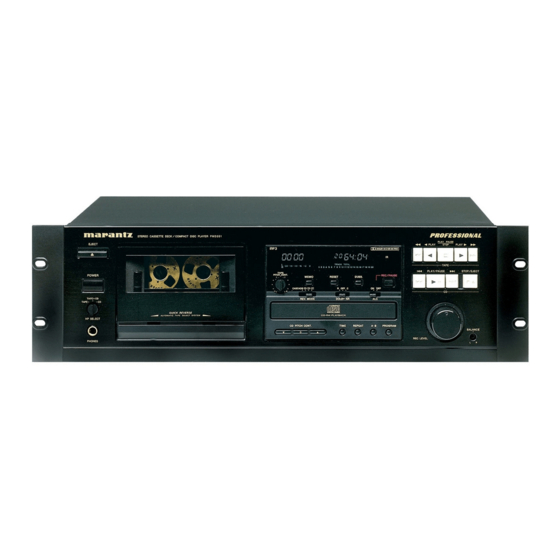
Stereo Cassette Deck / Compact Disc Player
STEREO CASSETTE DECK/COMPACT DISC PLAYER PMD351
EJECT
POWER
TAPE+CD
CD
TAPE
QUICK REVERSE
AUTOMATIC TAPE SELECT SYSTEM
HP SELECT
PHONES
TABLE OF CONTENTS
PMD351
PLAY PAUSE
PLAY
STOP
PLAY
DOLBY B-C NR HX PRO
IR
TAPE
PLAY/PAUSE
TAPE
PITCH CONT
REC/PAUSE
MEMO
RESET
DUBB.
CASCADE
B
OFF
C
ON
OFF
-
+
CD
REV.MODE
DOLBY NR
ALC
CD-RW PLAYBACK
CD PITCH CONT.
TIME
REPEAT
A-B
PROGRAM
0
REC LEVEL
PMD351 /
N1B/U1B
STOP/EJECT
BALANCE
L
R
PAGE
R
02AT855010 MIT
First Issue 2003.02
Advertisement
Table of Contents

Related Manuals for Marantz PMD351 N1B


Summary of Contents for Marantz PMD351 N1B
-
Page 1: Table Of Contents
All manuals and user guides at all-guides.com Service PMD351 / N1B/U1B Manual Stereo Cassette Deck / Compact Disc Player STEREO CASSETTE DECK/COMPACT DISC PLAYER PMD351 PLAY PAUSE EJECT PLAY STOP PLAY DOLBY B-C NR HX PRO TAPE PLAY/PAUSE STOP/EJECT TAPE POWER PITCH CONT REC/PAUSE... - Page 2 Parts for your MARANTZ equipment are generally available to our National Marantz Subsidiary or Agent. ORDERING PARTS : Parts can be ordered either by mail or by Fax.. In both cases, the correct part number has to be specifi ed.
-
Page 3: Technical Specifications
All manuals and user guides at all-guides.com 1. TECHNICAL SPECIFICATIONS TAPE DECK COMMON PART Track System ..........4 Track, 2 Channel Power Supply Recording/Erasure System......AC 105 kHz Bias /U ...............120V AC 60Hz Head System (Rotary type combination) /N ...............230V AC 50Hz Rec Play Head ........ -
Page 4: Service Hints And Tools
All manuals and user guides at all-guides.com 2. SERVICE HINTS AND TOOLS SERVICE HINTS SERVICE TOOLS Audio signals disc 4822 397 30184 Disc without errors (SBC444)+ Disc with DO errors, black spots and fingerprints (SBC444A) 4822 397 30245 Disc (65 min 1kHz) without no pause 4822 397 30155 Max. -
Page 5: Test Equipment Required For Servicing
All manuals and user guides at all-guides.com 3. TEST EQUIPMENT REQUIRED FOR SERVICING For measuring or checking a Cassette Deck, the following instruments and materials are necessary. • Audio Oscillator (Audio Signal Generator) • Attenuator (600 ohm) • Audio Noise Meter •... - Page 6 All manuals and user guides at all-guides.com (B) S.R.L. (Standard Recording Level) The Standard Recording Level is a signal of 250nWb/m on a tape at *OPEN CIRCUIT MAGNETIC FLUX. The relation between the recording level and a test tape is as follows. •...
- Page 7 All manuals and user guides at all-guides.com ADJUSTMENT FLOW CHART Start TAPE SPEED Adjustment AZIMUTH Adjustment PLAY-BACK EQ Adjustment or Check PLAY-BACK LEVEL Adjustment MPX Filter Adjustment BIAS FREQUENCY Adjustment BIAS OSC Coil HX Coil LEVEL METER Sensitivity Check REC/PB FREQUENCY Response Adjust. NORMAL Tape HIGH POSITION Tape METAL Tape...
- Page 8 All manuals and user guides at all-guides.com ADJUSTMENT POINT COMPONENT SIDE...
- Page 9 All manuals and user guides at all-guides.com 4.1 TAPE SPEED ADJUSTMENT 1) Playback the middle part of the Wow & Flutter test tape. 2) Adjust the variable resistor. ADJUSTMENT POINT RM36 for 3000Hz (2990Hz - 3010Hz). 3) Repeat 1) and 2) for both directions. 4.2 HEAD AZIMUTH ADJUSTMENT and FREQUENCY RESPONSE CHECK 1) Playback the 12.5 kHz part of the Azimuth test tape.
- Page 10 All manuals and user guides at all-guides.com 4.4 MPX FILTER ADJUSTMENT 1) Put the unit in REC mode with a S.R.L. input. 2) The MPX fi lter switch ON and change the input frequency to 19kHz(±10Hz). 3) Adjust L601(L), L602(R) for minimum output at the LINE OUTPUT jacks.
- Page 11 All manuals and user guides at all-guides.com 4.7 REC/PLAYBACK FREQUENCY RESPONSE ADJUSTMENT 1) Adjust the output level of the audio oscillator to 5.0mV (-26dB) from the S.R.L. recording condition. Record 400Hz and 12.5kHz signals with DOLBY OFF. 2) Playback the recorded part and confi rm the level of differences between 400Hz and 12.5kHz are within ±...
-
Page 12: Technical Description
All manuals and user guides at all-guides.com Example Reception Time Command code 2011 5. TECHNICAL DESCRIPTION How to use the RS-232C connector 0x40 0x31 0x32 0x30 0x31 0x31 0x0d This input/output connector (D-Sub 9-pin female) is used for When transmitting commands consecutively, put more RS-232C external control. - Page 13 All manuals and user guides at all-guides.com • Status confi rmation command • Status transmission When to confi rmation of the RS232C operations, the The status packets have a fi xed data length of 8 bytes. following Status transmitting requirement commands is ASCII codes from 0x00 to 0x7f are used to transmit serial transmitted to PMD351, status condition is replies.
-
Page 14: Service Procedure
All manuals and user guides at all-guides.com 6. SERVICE PROCEDURE Emergency Eject 1. To open the stucked tray, insert a minus driver into the hole of bottom and push the eject lever. 2. Use a minus driver. (width is about 4 mm) This picture shows the unit upside down. -
Page 15: Service Mode
All manuals and user guides at all-guides.com 7. SERVICE MODE 1. How to enter into the Service Mode While pressing PROGRAM, STOP/EJECT(CD) and STOP(TAPE) buttons, press POWER button. " *** 00 " is diaplayed " *** " is Version number of the microprocessor. 2. - Page 16 All manuals and user guides at all-guides.com Personal notes:...
-
Page 17: Wiring Diagram
All manuals and user guides at all-guides.com 8. WIRING DIAGRAM TO CD MECHA MECHA TO CASSETTE MECHA... -
Page 18: Block Diagram
All manuals and user guides at all-guides.com 9. BLOCK DIAGRAM PJ03 MAIN PCB AUTO REVERSE PG03 Cassette Block R/P SWITCH R/P HEAD APE MECHANISM Q802 EQ AMP uPC1330(15V) ALPS CMAY2Z3 VOLUME NJM2068 E-HEAD/ HXPRO Motor Drive/Tape count ... uPC1297 Mic Input Tape Out J803 0.5mV/10K... -
Page 19: Schematic Diagram
All manuals and user guides at all-guides.com 10. SCHEMATIC DIAGRAM S601 MPX_SW PJ03-1/4 RECL_IN RECL_IN RECR_IN RECR_IN ALC_L CK01 ALC_L 0.47/50V ALC_R ALC_R WJ01A +5VA MICL_IN MICL_IN Q603 QK01 MICR_IN MICR_IN DTC114ES DTC323TS DUBB RK01 DUBB T601 3.3k L601 TAPEL CK03 RK09 TAPEL... - Page 20 All manuals and user guides at all-guides.com RG51 PV03 WV11 RV01 HEADPHONE RG54 CV01 10/16V PJ03-2/4 RG53 RV03 RV02 RG52 RG17 RG19 LV01 +15V 100k RV05 CV02 10/16V RV11 SV01 CV03 CG07 RG28 HP SELECT RV04 PG03 10/16V 47/16V WG01 REC VOL.
- Page 21 All manuals and user guides at all-guides.com PY03 & PY13 JY01 TO JY61 RY28 VY01 SP-F 100K (PJ03) -30V SP-V SEG1 SEG2 RY51 SP-COM 5k B SEG3 PITCH CONT SEG4 SEG5 JY71 JY02 SEG6 SY73 CD_LED SY77 NEXT SEG7 DY73 DY77 RPLAY_LED SEG8...
- Page 22 All manuals and user guides at all-guides.com TO JU54 (PS01) TO J303 (PS01) J802 JT01 LT01 JT02 PULSE TRANS CT01 RT01 CAXL PJ03-3/4 270R CT05 RT02 560R CT02 CT04 CT03 4700P 0.022 2200P Q801 NJM7815FA C804 JU04 C803 100/25V 2200/35V PT03 L001 +15V...
- Page 23 All manuals and user guides at all-guides.com CR07 PR01 CR08 RR35 JR03 JR02 CR06 CR05 +5VD JU53 RR36 RS-232C RR38 FLSTB RR39 RR37 TO FRONT PART (D-sub) FLCLK CPU_RES CPU_RES FLDIN JY04 (PY13) CR10 CR11 FLDOUT TO FRONT PART 220P 220P JY01 (PY13) JY62...
- Page 24 All manuals and user guides at all-guides.com R211 R212 R213 Q113 Q114 Part of RF AMP 2SC4081 2SC4081 PS01-2/3 J101 FPC15 +5VA RAD- Q101 R110 TZA1024T/N1 R101 FOC+ Laser H: Laser on TRACKING 4.7k 2.6V FOC- RW H: CD-RW Play C106 4.8V 47/10V...
- Page 25 All manuals and user guides at all-guides.com TO JT01 (PJ03) J303 PS01-3/3 Radial Radial R363 FOCUS R343 +2.7V FOCUS +3.3V +3.3V C355 Sledge Sledge C341 MOTO1 MOTO1 R347 R358 R342 Part of CD Decoder C358 +5VD C326 C304 R356 +2.7V C309 INSW C364...
-
Page 26: Parts Location
All manuals and user guides at all-guides.com 11. PARTS LOCATION PJ03 QE02 QE01 QE22 QE21 QE44 QE43 QU03 - QU05 QU02 QU09 QU08 Q851 QE04 QG02 QG01 QE03 QE41 Q807 Q805 QE23 Q808 Q801 Q901 QG03 QG05 QG06 QC04 -QC01 Q903 Q902 QL03 QU06 Q804Q803 Q806... - Page 27 All manuals and user guides at all-guides.com PY03, PY13 QY02 QY01 QY01 PY23 PY33...
- Page 28 All manuals and user guides at all-guides.com PS03 PG03 PT03 PP01 PV03 QV01 QR01...
- Page 29 All manuals and user guides at all-guides.com PS01 QU53 QU52 Q383 Q304 Q352 QU51 QU64 - QU61 Q111 Q112 Q101 Q102 Q113 Q114 Q106 Q107 Q104 Q103 Q303 Q110 Q302 Q109 Q301 Q108 Q105 Q382 Q381 Q351...
-
Page 30: Microprocessor And Ic Data
All manuals and user guides at all-guides.com 12. MICROPROCESSOR AND IC DATA Q303:BU2630FV Pin descriptions Q381:CS4338 SERIAL DATA INPUT SDATA AOUTL ANALOG LEFT CHANNEL OUTPUT DE-EMPHASIS / SCLK DEM/SCLK ANALOG POWER LEFT / RIGHT CLOCK LRCK AGND ANALOG GROUND MASTER CLOCK MCLK AOUTR ANALOG RIGHT CHANNEL OUTPUT... - Page 31 All manuals and user guides at all-guides.com Q351:STA016 Pin Description Pin Name Type Description Sourde/Dest CDDSP interface CD_LRCK DSP Interface left/right Clock From DSP CD_SDI DSP interface serial data From DSP CD_BCK DSP interface bit clock From DSP SDI interface BS_SDI Bitstream interface serial data From MCU...
- Page 32 All manuals and user guides at all-guides.com Q351:STA016 Pin Name Type Description Sourde/Dest HANDSHAKE SIGNALS Strobe signal From MCU RQST I2C data signal To MCU C LINK I2C clock signal From MCU I2C data signal To MCU MISCELLANEOUS Oscillator input Oscillator output Buffered output clock CLKOUT...
- Page 33 All manuals and user guides at all-guides.com QR01 : HIN202ECB V C C 0.1µF TO P VIEW C 1+ +5V T O 10V 0.1µF V O LTA GE INV ER TE R C 1- C 1+ V C C C 2+ +10V TO -10V G ND 0.1µF...
- Page 34 All manuals and user guides at all-guides.com Q301:SAA7324 Pin Description SYMBOL DESCRIPTION HFREF comparator common mode input HFIN comparator signal input ISLICE current feedback output from data slicer analog ground 1 SSA1 analog supply voltage 1 DDA1 reference current output pin reference voltage for servo ADC's unipolar current input (central diode signal input) unipolar current input (central diode signal input)
- Page 35 All manuals and user guides at all-guides.com Q301:SAA7324 V SSA2 V DDA2 V SSD2 V DDD1(P) V SSA1 V DDA1 V SSD1 V SSD3 V DDD2(C) D1 D2 PRE- CONTROL PROCESSING FUNCTION OUTPUT STAGES V ref V RIN GENERATOR CONTROL PART LDON MICROCONTROLLER...
- Page 36 All manuals and user guides at all-guides.com QU51 : µPD784217AGC-192-8EU...
- Page 37 All manuals and user guides at all-guides.com QU51 : µPD784217AGC-192-8EU No. Port Name Signal Name Remarks No. Port Name Signal Name Remarks 1 P120/RTP0 n.c. n.c. 51 P83/A3 Reel motor1 on/off 2 P121/RTP1 n.c. n.c. 52 P84/A4 Reel motor2 on/off 3 P122/RTP2 n.c.
-
Page 38: Exploded View And Parts List
All manuals and user guides at all-guides.com 13. EXPLODED VIEW AND PARTS LIST 5 1 2 6 4 X 1 5 ( U) MARK MATERIAL /F INIS H SYMBOL STYLE PART S NAME (M ) STEEL /C OPPER 5 1 0 6 + P. - Page 39 02AT851020 USER GUIDE CD-ROM 02AT851020 NOT STANDARD SPARE PARTS 001S PACKING CASE 02AT801010 002S CUSHION 457T809010 001D LID TOP COVER 418T257030 005D SIDE BRACKET (L&R) 457T160110 NOTE : "nsp" PART IS LISTED FOR REFERENCE ONLY, MARANTZ WILL NOT SUPPLY THESE PARTS.
- Page 40 HW1000100R PHOTO REFLE SUPPLY HW1000100R [AW13G-00] Q076 HW1000200R QUICK SENSOR ASSY [AZ13P-00] HW1000200R S073 *SP000130R SWITCH [UE16E-11] *SP000130R S076 S077 *SP000130R CRO2 SW [UE16E-11] *SP000130R NOTE : "nsp" PART IS LISTED FOR REFERENCE ONLY, MARANTZ WILL NOT SUPPLY THESE PARTS.
- Page 41 All manuals and user guides at all-guides.com...
- Page 42 VERS. PART NO. PART NO. DESCRIPTION COLOR (FOR EUR) (MJI) QP40410986 SUSPENSION(4822 404 10986) QP40410986 QP40111709 CLAMPER(4822 401 11709) QP40111709 QP35810266 BELT(4822 358 10266) QP35810266 NOTE : "nsp" PART IS LISTED FOR REFERENCE ONLY, MARANTZ WILL NOT SUPPLY THESE PARTS.
-
Page 43: Electrical Parts List
All manuals and user guides at all-guides.com 14. ELECTRICAL PARTS LIST NOTE ON SAFETY FOR FUSIBLE RESISTOR : ASSIGNMENT OF COMMON PARTS CODES. RESISTORS The suppliers and their type numbers of fusible resistors : 1) GD05 × × × 140, Carbon film fixed resistor, ±5% 1/4W are as follows;... - Page 44 DTC144ES UN4213 47K 47K D871 QG06 BA20002000 DIG.TRS. BA20002000 DIODE HD20002000 DTC144ES UN4213 47K 47K D874 1SS176 MA165 1SS254 30V 0.1A QJ01 HC10206060 IC UPC1330HA HEAD SWITCH HC10206060 NOTE : "nsp" PART IS LISTED FOR REFERENCE ONLY, MARANTZ WILL NOT SUPPLY THESE PARTS.
- Page 45 SS02020970 SLIDE SWITCH MPX FILTER SS02020970 C312 EY10601620 TANTL. CHIP 10µF 16V EY10601620 SSSUI-6MM KNOB C313 EY47601020 TANTL. CHIP 47µF 10V EY47601020 C314 CER. CHIP 180pF DD95181300 NOTE : "nsp" PART IS LISTED FOR REFERENCE ONLY, MARANTZ WILL NOT SUPPLY THESE PARTS.
- Page 46 CER. CHIP 39pF ±5 % CG 50V DD95390300 CHIP 10kΩ ±5% 1/16W NN05103610 C396 CER. CHIP 27pF DD95270300 R315 C397 CER. CHIP C1608X7R1H104K DK96104300 R316 CHIP 47Ω ±5% 1/16W NN05470610 NOTE : "nsp" PART IS LISTED FOR REFERENCE ONLY, MARANTZ WILL NOT SUPPLY THESE PARTS.
- Page 47 BA10014210 DIG.TRS. DTA144EU BA10014210 R391 CHIP 0Ω ±5% 1/16W NN05000610 QU63 BA20021210 DIG.TRS. DTC144EC BA20021210 R392 CHIP 0Ω ±5% 1/16W NN05000610 QU64 BA10014210 DIG.TRS. DTA144EU BA10014210 NOTE : "nsp" PART IS LISTED FOR REFERENCE ONLY, MARANTZ WILL NOT SUPPLY THESE PARTS.
- Page 48 HI10062320 L.E.D. LT3D8B RED 3O REC IND. HI10062320 DY10 HW10004210 PHOTO UNIT RPM6936-V4 HW10004210 IR SENSOR QY01 HC10283060 IC UPD16311GC-AB6 FTD DRIVER HC10283060 QY02 HT10001000 TRS. A1048 A933S A1267 ETC. HT10001000 NOTE : "nsp" PART IS LISTED FOR REFERENCE ONLY, MARANTZ WILL NOT SUPPLY THESE PARTS.
Need help?
Do you have a question about the PMD351 N1B and is the answer not in the manual?
Questions and answers