Advertisement
Table of Contents
- 1 Max. Voltage
- 2 Max. Current
- 3 Front Panel Descriptions
- 4 Back Panel Descriptions
- 5 Technical Parameters
- 6 Installation
- 7 Constant Voltage / Constant Current Characteristics
- 8 Operating Procedures
- 9 Constant Current Operation
- 10 Battery Charging Operation
- 11 Troubleshooting and Maintenance
- 12 Fuse Replacement
- Download this manual
Advertisement
Table of Contents

Subscribe to Our Youtube Channel
Related Manuals for Mastech HY1520EX


Summary of Contents for Mastech HY1520EX
- Page 1 REGULATED DC POWER SUPPLY USER MANUAL SINGLE OUTPUT SWITCH MODE DC POWER SUPPLY...
- Page 2 Please read this manual carefully before operating the power supply. 1. Introduction Volteq HY series single output switch mode DC power supplies are regulated variable DC power supplies designed to provide the most often required DC outputs in scientific and research institutions, schools and colleges, industrial R&D, as well as manufacturing and testing.
-
Page 3: Max. Voltage
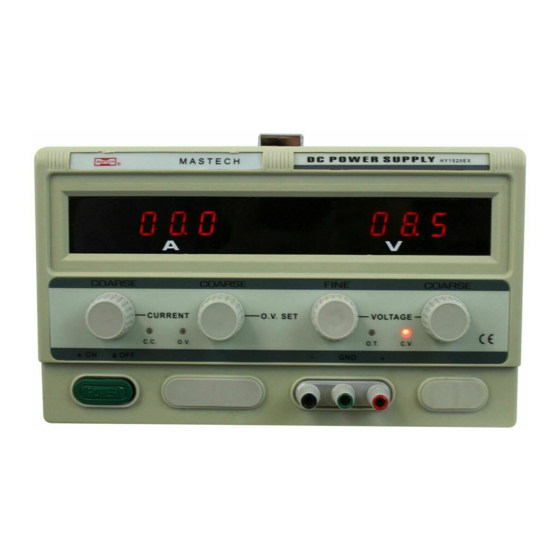
Temperature: -10°C to 40°C Relative humidity: <80% Table 2-1 Model Max. Voltage Max. Current Fuse Rating Weight (lbs) HY1520EX 10A/250V HY1530EX 10A/250V HY3010EX 10A/250V HY3020EX 10A/250V HY3030EX 15A/250V HY5020EX 15A/250V HY6020EX 15A/250V 2-2 Front Panel Descriptions (1) Trademark: Volteq. (2) Digital ammeter: displays the actual output always; this equates to the set value if in CC mode. - Page 4 (6) OV indicator: this indicator turns red when the power supply is over-voltage protected. The power supply will not respond to user control until it's reset (See 4-2). (7) On/Off Power button: When this button is pushed to "In" position, the power supply is turned on; conversely, the power supply is off when this button is in the "Out"...
-
Page 5: Back Panel Descriptions
output terminal ("-") is usually shorted with “GND”. Only select models include the front terminals. Warning: the front terminals are rated for less than 10A only. Use only the rear output terminals if current draw is more than 10A, and tighten the connection to reduce contact resistance. Warning: For electrochemical applications (e.g., plating and anodizing), remove the short connector between “–”... - Page 6 (16) Positive Terminal. (17) Negative Terminal. (18) Ground Terminal: this is connected to the case. (19) Cooling fan: the fan is turned on briefly when the power supply is energized; afterwards it is turned on when internal temperature of the power supply rises above 45℃. (20) AC voltage selector switch: use this switch to select the input AC of either 110V or 220V for select models.
-
Page 7: Technical Parameters
2-3 Technical Parameters 1) Voltage stabilization: ≤0.2% 2) Current stabilization: ≤0.5% 3) Load stabilization: ≤0.3% 4) Ripple and noise: ≤1%( RMS) 5) Display accuracy: ±1%±1 digit 3. Operation Instructions 3-1 Installation 1) Before plugging into AC outlet The input voltage of the power supply is typically shown on the top rear part of the case. AC voltage should be within 10% of the input voltage specified, e.g., if the specified input voltage is 110V, the power supply will work with AC voltage of 110V±10%. - Page 8 selector switch as shown in picture below: Warning: Changing the AC voltage selector setting must be done with the power supply unplugged from AC. Warning: To avoid electrical shock, the grounding conductor of the power cord must be connected to AC ground. Warning: Do not connect any load to the power supply before it's turned on.
-
Page 9: Constant Voltage / Constant Current Characteristics
3-2 Constant Voltage / Constant Current Characteristics The power supply is a regulated constant current / constant voltage (CC CV) power supply, which is characterized by automatic crossover from constant current (CC) to constant voltage (CV), and vise versa. At any moment, the power supply automatically determines whether to operate in CV or CC mode, depending on the voltage and current limit (set by the front knobs), and the load connected (if no load is connected, it simply means that the load resistance is infinite;... -
Page 10: Operating Procedures
becomes the lower limit, and the output current remains constant and the output voltage drops in proportion to the further decrease of the load resistance. Similarly, crossover from constant current (CC) to constant voltage (CV) mode automatically occurs when the resistance of the load is increased. -
Page 11: Constant Current Operation
switch first before turning this button on; conversely, turn this button off before switching off the air switch in the back. For the models without air switch, this button turns the power on and off. 1) Constant Voltage (CV) Operations e) Adjust current knobs (knobs 3 or 4) to slightly above zero so that CV indicator light is on, and set voltage (knobs 12 and 13) to the desired output voltage. -
Page 12: Battery Charging Operation
h) Once finished, turn the current down to < 1A, disconnect the load, and then turn off the power supply. 3) Battery Charging Operation Warning: at no time should the battery be connected to the power supply when the power supply is turned off, or with the output voltage of the power supply set to lower than the battery voltage. - Page 13 k) Disconnect the battery from the power supply, and then turn off the power supply. 4) Inductive Load Warning: it is critical to change the current on the inductive load slowly. Sudden changes of power supply output can cause the inductive load to generate a reverse EMF much larger than the voltage from the power supply, and cause damage to the power supply.
- Page 14 the current limit to the maximum value allowed by the power supply. 1) With no load connected, turn all 4 knobs to minimum position. Turn the power supply on. Caution: For models with air switch, the green On/Off button enables/disables the output. Turn on the air switch first before turning this button on;...
-
Page 15: Troubleshooting And Maintenance
For very sensitive applications, it maybe desirable to set OV level to a specific value, by following the steps below: 1) Determine the maximum voltage allowed by the your application (the OV limit). This should be slightly higher than the operating voltage. If for whatever reason there is a voltage surge above this limit (measured at the output terminals), the OV light will turn red, and the power supply will no longer respond to user input (with the output turned off). -
Page 16: Fuse Replacement
4-1 Fuse Replacement Some models are equipped with air switch, which is a reset-able breaker and does not require a fuse. The rest of the models are equipped with a fuse. If the fuse is blown, the power supply will not turn on. It is a good idea to determine and correct the cause of the blown fuse, then replace only with a fuse of the correct rating and type. - Page 17 already set it up properly. 3) Turn the voltage knobs down (knob 12 & 13). 4) With no load connected, turn the power supply on. The power supply is reset and ready to be used. 4-3 Recovery from Over-temperature Protection If the internal temperature is too high, the power supply is disabled due to over-heating, and the OT indicator turns red.
- Page 18 Warranty: this product is covered by standard one-year manufacturer’s warranty, which includes parts and labor for one year from the date of purchase.
Need help?
Do you have a question about the HY1520EX and is the answer not in the manual?
Questions and answers