Advertisement
Advertisement
Table of Contents

Related Manuals for Mastech HY1503D


Summary of Contents for Mastech HY1503D
- Page 1 LINEAR DC POWER SUPPLY USER MANUAL REGULATED LINEAR DC POWER SUPPLY...
- Page 2 Please read this manual carefully before operating the power supply. 1. Introduction The variable DC power supplies covered in this manual are regulated linear DC power supplies designed for laboratory, school and manufacturing applications. The output voltage and current can both be continuously adjusted from 0 to maximum rated value by means of the coarse and fine potentiometers.
-
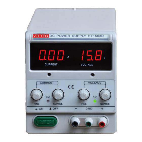
Page 3: Front Panel Descriptions
Storage environment: Temperature:-10 C to 70 Relative humidity: <70% Table 2-1 Model Max. Voltage Max. Current Fuse Rating Dimension (mm) HY1503D 5A/250V 270×128×145 GPS-1850D 5A/250V 270×128×145 HY3003D* 5A/250V 270×128×145 HY3005D* 5A/250V 270×128×145 HY3006D 5A/250V 270×128×145 HY6002D 5A/250V 270×128×145 HY6003D 5A/250V 270×128×145... - Page 4 Figure 1 (3) Current fine: for fine adjustment of the current limit. (4) CC indicator: lights when the current limit is set lower than the voltage limit, and the power supply operates in constant current (CC) mode. (5) Current coarse: for coarse adjustment of the current limit.
-
Page 5: Back Panel
(6) Current Range: When pushed to "In" position, the current limit is changed to half of the set value; when this button is in "Out" position, the current limit is at the full set value. This button is not available on all models. (7) Voltage fine: for the fine adjustment of the voltage limit. -
Page 6: Technical Parameters
2-3 Technical Parameters 1) CV mode: Line regulation: <0.01%+3mV Load regulation: < 0.01%+3mV (Max. current<3A) Load regulation: < 0.01%+5mV (Max. current>3A) Ripple & noise : < 0.5mVrms (5Hz-1MHz) (Max. current <3A) <1.0mVrms (5Hz-1MHz) (Max. current >3A) < 100μS (load-variant 50%, min. load current 0.5A) Recovery time : Temperature coefficient: <... - Page 7 2) CC Mode: Line regulation: <0.2%+3mA Load regulation: < 0.2%+3mA Ripple & noise : < 3mArms 3) Display accuracy: ±1%±1 digit 3. Operation Instructions 3-1 Precaution 1) AC input AC input should be within the range of line voltage of 110V/220V at 50/60Hz. Before plugging the power supply into the wall outlet, make sure that the AC selection switch (located in the back) shows the correct value in the middle, i.e.
-
Page 8: Setting Current Limit
Warning: Do not connect any load to the power supply before it's turned on. Likewise, make sure to disconnect the load before shutting down the power supply. Damages to the power supply can happen if you do not follow this. Such damages are not under warranty. Warning: If you are running an inductive load like magnetic coils, DC motors, stepper motors, etc., make sure to connect your load with the output set to zero and change the voltage/current slowly, and NEVER turn the power supply on or off with a inductive load connected! -
Page 9: Constant Voltage / Constant Current Characteristics
3) Adjust the COARSE VOLTAGE knob (knob 10) away from zero sufficiently for the CC indicator to light. 4) Adjust the coarse and fine CURRENT controls (knob 3 & 5) for the desired current limit. 5) The current limit (overload protection) has now been preset. Do not change the CURRENT control setting after this step. -
Page 10: Operating Procedures
to CC. Similarly, crossover from constant current to constant voltage mode automatically occurs when the resistance of the load is increased. A good example of this is charging a 12V lead acid battery. Initially, the open circuit voltage of the power supply may be set at 13.8V. A discharged battery may demand high charging current beyond the current limit set for the power supply, and it will operate at constant current mode, with the maximum charging current equal to the set current limit. - Page 11 correctly. g) Once the load is connected, turn the current knobs to maximum, to ensure that the power supply stays at CV mode. If you want to limit the current and operate at the CV mode, follow 3-2 first to set the current limit, and do not change the setting on current knob during this setup.
-
Page 12: Maintenance
4. Maintenance Warning: The following instructions are to be performed by qualified personnel only. To avoid electrical shock, do not perform any servicing other than the contained in the operation instructions unless you are qualified to do so. For further questions, please contact factory support at support@volteq.com. 4-1 Fuse Replacement If the fuse is blown, the power supply will not turn on. - Page 13 is done by changing the selection switch in the back. Warning: The default setting is 110V AC; to use the unit for 220V AC, make sure to perform the following procedures before plugging the power supply into AC outlet: 1) Make sure power cord is unplugged. 2) Change the AC selector switch to the desired line voltage position.
Need help?
Do you have a question about the HY1503D and is the answer not in the manual?
Questions and answers