Advertisement
Advertisement
Table of Contents

Related Manuals for Mastech HY1503D


Summary of Contents for Mastech HY1503D
- Page 1 LINEAR DC POWER SUPPLY USER MANUAL REGULATED LINEAR DC POWER SUPPLY...
- Page 2 Please read this manual carefully before operating the power supply. 1. Introduction The variable DC power supplies covered in this manual are regulated linear DC power supplies designed for laboratory, school and manufacturing applications. The output voltage and current can both be continuously adjusted from 0 to maximum rated value by means of the coarse and fine potentiometers.
-
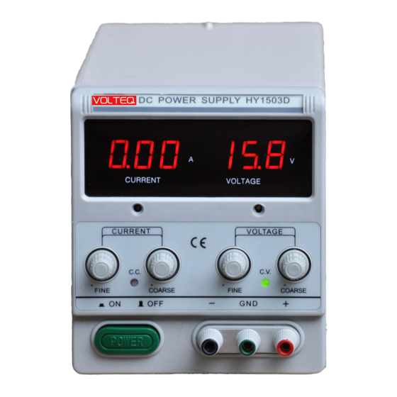
Page 3: Front Panel Descriptions
Storage environment: Temperature:-10 C to 70 Relative humidity: <70% Table 2-1 Model Max. Voltage Max. Current Fuse Rating Dimension (mm) HY1503D 5A/250V 270×128×145 HY1803D 5A/250V 270×128×145 GPS-1850D 5A/250V 270×128×145 HY3003D* 5A/250V 270×128×145 HY3005D* 5A/250V 270×128×145 HY3006D 5A/250V 270×128×145 HY6003D 5A/250V 270×128×145... - Page 4 (2) Digital voltmeter: Displays the actual output voltage; this equates to the set value when in CV mode. (3) Current calibration: Use this screw to calibrate the current meter if necessary. (4) Voltage calibration: Use this screw to calibrate the voltage meter if necessary.
- Page 5 (11) CV indicator: this indicator turns red when the power supply is in constant voltage (CV) mode (See 3-2). (12) Power button: When this button is pushed to "In" position, the power supply is turned on, and the display comes on; conversely, the power supply is off when this button is in the "Out"...
-
Page 6: Technical Parameters
Warning: the voltage indicated on the AC selector switch must match the AC voltage, otherwise the power supply will be damaged (plugging a power supply rated for 110V into 220V AC), or the maximum output would not be reached (plugging a 220V power supply into 110V AC). Damage caused by plugging into wrong AC voltage is not under warranty. -
Page 7: Installation
Load regulation: < 0.2%+3mA Ripple & noise : < 3mArms 3) Display accuracy: ±1%±1 digit 3. Operation Instructions 3-1 Installation 1) Before plugging into AC outlet Warning: The correct input voltage of the power supply is shown on the AC selector switch, e.g. for 120V AC, the switch itself should show 110V on the voltage selector switch as shown in picture below: The AC voltage should be within 10% of that, e.g., if the specified input voltage is 110V, the power supply will work with AC voltage of 110V±10%. -
Page 8: Constant Voltage / Constant Current Characteristics
Warning: Make sure the output is stopped before turning the power supply on or off. Shutting down improperly can cause the power supply to fail when it’s turned on next time. Damages due to improper startup and/or shutdown are not under warranty. Warning: When running an inductive load like magnetic coils, DC motors, stepper motors, etc., make sure to set the output to zero before turning on the output;... - Page 9 law, so only one of the two is an independent variable. The law dictates that the output current I in amps (A) is always equal to the output voltage V in volts (V) divided by the load resistance R in ohms (Ω): For example, if the load resistance (R) is such that the current limit (set by knobs 5 and 6) is higher than the voltage limit (set by knobs 7 and 8) divided by R (i.e., voltage limit is lower than current limit for the load R connected), the power supply operates in the constant voltage (CV) mode.
-
Page 10: Operating Procedures
The crossover is signaled by the indicator light changing from CC to CV. 3-3 Operating Procedures Warning: Make sure the output is stopped when connecting or disconnecting a load. Warning: If load resistance is <1 ohm, make sure the voltage is set to <5V when enabling the output. a) Make sure that the AC voltage matches the input voltage shown on the AC selector switch. -
Page 11: Constant Current Operation
h) Push the output button in to enable output; turn up the current knobs to maximum, or leave the current knobs unchanged if correct current limit has been set following section 3-4. Once finished, stop the output, and then turn off the power supply. For applications with the same settings, skip steps d)-g), and simply connect the load before enabling output. - Page 12 current meter is reading the maximum charging current recommended by the battery manufacturer. If the CV light is on, either the battery is not depleted enough or the current limit is set too high. Watch the charging progress, when the current is below 1A or 1/10 of the maximum charging current, it is probably time to end the charge.
-
Page 13: Troubleshooting And Maintenance
3-4 Setting Current Limit for CV Operation Note: this step is only needed if it is necessary to set a current limit for constant voltage operation or when charging a battery; for most of applications requiring constant voltage, simply turn the current knobs to maximum position, which sets the current limit to the maximum value allowed by the power supply. -
Page 14: Fuse Replacement
questions, please contact factory support at support@volteq.com. 4-1 Fuse Replacement All of the models mentioned are equipped with a fuse. If the fuse is blown, the power supply will not turn on. It is a good idea to determine and fix the cause of the blown fuse, then replace only with a fuse of correct rating and type. Warning: For continued fire protection, replace fuse only with fuse of the specified type and rating.
Need help?
Do you have a question about the HY1503D and is the answer not in the manual?
Questions and answers