Table of Contents
Advertisement
ASSEMBLY INSTRUCTIONS AND USER'S MANUAL
MY FIRST SKYFLYER METAL SWING SET
MODEL# MSC- 4580
FOR RESIDENTIAL USE ONLY
Save this instruction manual for future reference
For Customer Service, please call 1-866-370-2131 or visit
www.sportspowerltd.net
Monday – Friday 9:00 AM – 5:00 PM Eastern Time
SPORTSPOWER LTD.
LEVEL 20, PARKVIEW CENTRE,7 LAU LI STREET, CAUSEWAY BAY, HONG KONG
Advertisement
Table of Contents

Related Manuals for SPORTSPOWER MY FIRST SKYFLYER


Summary of Contents for SPORTSPOWER MY FIRST SKYFLYER
- Page 1 ASSEMBLY INSTRUCTIONS AND USER’S MANUAL MY FIRST SKYFLYER METAL SWING SET MODEL# MSC- 4580 FOR RESIDENTIAL USE ONLY Save this instruction manual for future reference For Customer Service, please call 1-866-370-2131 or visit www.sportspowerltd.net Monday – Friday 9:00 AM – 5:00 PM Eastern Time SPORTSPOWER LTD.
- Page 2 Dear Valued Customer, Congratulations on your Sportspower play set purchase! Please read and completely understand the contents of this owner’s manual. This manual contains specific instructions and warnings that must be followed to prevent injuries. This play set is for residential use only. This play set is NOT intended for public or commercial use. The warranty will be voided if the play set is used in a commercial application.
-
Page 3: Table Of Contents
TABLE OF CONTENTS IMPORTANT WARNINGS AND INSTRUCTIONS ................4 IMPORTANT CONSUMER INFORMATION SHEET ................6 OPERATING INSTRUCTIONS……………………………………………………..….. …………..……..7 ANCHORING ................................ 8 CARE AND MAINTENANCE CHECKLIST ..................10 COMPLETE PRODUCT VIEW ....................... 11 PARTS LIST .............................. 12 HARDWARE PARTS LIST ........................13 ASSEMBLY AND INSTALLATION INSTRUCTIONS ................ -
Page 4: Important Warnings And Instructions
IMPORTANT WARNINGS AND INSTRUCTIONS Trhbrt WARNING READ ALL INSTRUCTIONS BEFORE ASSEMBLING OR USING THIS EQUIPMENT AGE LIMIT This product is designed to be used by maximum two (2) children between the ages of 3 to 8. Maximum user weight is 100 lb (45kg) each with a combined maximum weight of 200 lb (90kg). Do not allow children under three (3) years old nearby during assembly due to choking hazard from small parts. - Page 5 Trhbrt IMPORTANT WARNINGS AND INSTRUCTIONS INSPECTION PRIOR TO EACH USE OR DAILY INSPECTION DO NOT use the equipment if any bolts or nuts are missing or loose. ALWAYS check to ensure the equipment and all parts are well secured and stable before each use. ALWAYS clear the play area of any rocks, sharp objects, or any materials that could be potentially hazardous to users.
-
Page 6: Important Consumer Information Sheet
Trhbrt IMPORTANT CONSUMER INFORMATION SHEET The Consumer Product Safety Commission estimates there are about 200,000 playground related injuries involving children each year. Injuries involving this hazard pattern tend to be among the most serious of all playground injuries and have the potential to be fatal, particularly when the injury is to the head. The surface under and around playground equipment can be a major factor in determining the injury-causing potential of a fall. -
Page 7: Operating Instructions
Trhbrt OPERATING INSTRUCTIONS • Observing the following statements and warnings reduces the likelihood of serious or fatal injury. • Warning the owner to instruct children not to walk close to, in front of, behind, or between moving items. • Warning the owner to instruct children not to twist swing chains or ropes or loop them over the top support bar since this may reduce the strength of the chain or rope. -
Page 8: Anchoring
Trhbrt ANCHORING (NOTE: ANCHORS ARE NOT INCLUDED-MUST BE PURCHASED SEPARATELY) There are different ways of anchoring the equipment, depending on the type of ground on which the equipment is to be installed. Make sure that all anchors are below ground level to prevent tripping. - Page 9 Trhbrt ANCHORING TABLE OF CONTENTS FRAME 12-5/8” CONCRETE 5” 2” BRICK OR GRAVEL Note: The maximum fall height for this product is 6 feet. The minimum ground clearance between the bottom of the suspended plays and the playing or ground surface must be 8 inches.
-
Page 10: Care And Maintenance Checklist
Trhbrt CARE AND MAINTENANCE CHECKLIST AT THE BEGINNING OF EACH PLAY SEASON: Tighten all hardware. Lubricate all metallic moving parts per manufacturer’s instructions. Check all protective coverings on bolts, pipes, edges, and corners. Replace if they are loose, cracked, or missing. Check all moving parts including swing seats, ropes, cables and chains for wear, rust or other deterioration. -
Page 11: Complete Product View
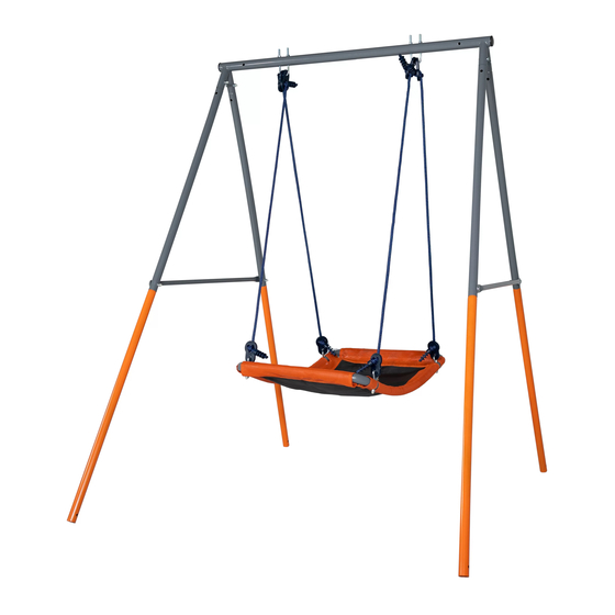
Trhbrt COMPLETE PRODUCT VIEW... -
Page 12: Parts List
Trhbrt PARTS LIST... -
Page 13: Hardware Parts List
Trhbrt HARDWARE PARTS LIST B2 x 4 pcs B1 x 8 pcs B3 x 2 pcs (5/16x48mm) ( 5/16 x 45 mm ) BOLT ( 5/16 x 50 mm ) BOLT ( 5/16 x 114 mm ) BOLT B5 x 18 pcs B4 x 18 pcs B6 x 12 pcs 5/16”... -
Page 14: Assembly And Installation Instructions
Trhbrt ASSEMBLY AND INSTALLATION INSTRUCTIONS STEP 1 Ø Insert Top Legs (# D) into the sockets on the Top Bar (#A). Align the holes and secure using B2, B5(2), B7 and B4 as shown below. Ø Repeat the same process for all four legs shown below. NOTE: For easier assembly, do not tighten the bolts all the way initially to allow room for adjustment. - Page 15 Trhbrt ASSEMBLY AND INSTALLATION INSTRUCTIONS STEP 2 Ø Attach Top Cross Bar (# B) to (# A) using B8, B6, G (2), B6, B7, B4 as shown below. Ø Attach the other end of (# B) to (#D) using B1, B6, G, B5, B7, B4 as shown below. Ø...
- Page 16 Trhbrt ASSEMBLY AND INSTALLATION INSTRUCTIONS STEP 3 Ø Connect Lower Legs (# E) to Top Legs (# D) and attach Cross Rails (# F) to the outer sides the swing frame. Secure using B1, B6, G, B5, B7and B4 as shown below. REMINDER: Once you have completed assembling the swing frame, make sure to go over the previous steps and fully tighten all the nuts and bolts and close the plastic caps.
-
Page 17: Area Of Installation - Two Person Flying Saucer
Trhbrt ASSEMBLY AND INSTALLATION INSTRUCTIONS STEP 4 Ø Slide Flying Saucer Tubes (# R4) and (# R5) into the pockets of Flying Saucer (# R7) as shown below. Connect the four tubes together and align the holes with the round holes facing downward. Diagram 4-1... - Page 18 Trhbrt ASSEMBLY AND INSTALLATION INSTRUCTIONS STEP 5 Ø Connect Rope (# R1) to the flying saucer. Insert (#R2A) and secure using F2 and F1 as shown below. Diagram 5-1...
- Page 19 Trhbrt ASSEMBLY AND INSTALLATION INSTRUCTIONS Ø Loop U-Bolt (#B3) through R1(2) and then place B9 on both sides of U-Bolt. Insert U-Bolt through Top Bar (#A) and secure using B5, B7, and B4 as shown below. Diagram 5-2 Congratulations! You have now completed installing the equipment. Please make sure to go back and check all hardware and ensure all bolts and nuts are securely tightened before using the playground equipment.
-
Page 20: Manufacturer's Limited Warranty
MANUFACTURER’S LIMITED WARRANTY Sportspower Ltd. warrants its overall product for 1 year from the date of purchase. This includes the foam pads, as well as all swing set parts. Products are warranted to be free of defects in material and workmanship under normal use and service conditions.
Need help?
Do you have a question about the MY FIRST SKYFLYER and is the answer not in the manual?
Questions and answers