
Related Manuals for Casio PX-330BK


Summary of Contents for Casio PX-330BK
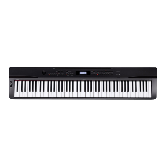
- Page 1 (without price) PX-330BK/PX-330WE AUG. 2009/SEP. 2011 PX-330BK ELECTRONIC KEYBOARD INDEX Ver. 5 : Sep. 2011...
-
Page 2: Table Of Contents
CONTENTS SPECIFICATIONS ........................1 BLOCK AND WIRING DIAGRAM .................... 3 PCB LAYOUT ........................... 4 CIRCUIT DESCRIPTION ......................5 PRINTED CIRCUIT BOARDS ....................7 DISASSEMBLY ........................13 DIAGNOSTIC PROGRAM ...................... 42 EXPLODED VIEW ........................PARTS LIST ..........................SCHEMATIC DIAGRAMS ....................... -
Page 3: Specifications
SPECIFICATIONS Keyboard 88-key piano keyboard, with Touch Response (3 types) Maximum Polyphony 128 notes Tones 250 (with Layer and Split) Effects Reverb (4 types), Chorus (4 types), Brilliance (–3 to 0 to 3), Acoustic Resonance Metronome Beats per measure: 0, 2, 3, 4, 5, 6 Tempo Range: 20 to 255 Duet Adjustable tone range: 0 to 3 octaves for the left keyboard;... - Page 4 Speakers [13 cm × 6 cm (rectangular)] × 2 + φ 5 cm × 2 (Output: 8.0 W + 8.0 W) Power Requirements AC Adaptor: AD-A12150LW Power Consumption 12 V 18 W Dimensions 132.2 (W) × 28.6 (D) × 13.5 (H) cm (52 × 11 × 5 inch) Weight Approximately 11.6 kg (25.6 lbs) * Based on 1 KB = 1024 bytes, 1 MB = 1024 bytes * Specifications and designs are subject to change without notice. – 2 –...
-
Page 5: Block And Wiring Diagram
BLOCK AND WIRING DIAGRAM KEYBORAD PCB KEYBORAD PCB KEYBORAD PCB KEYBORAD PCB (MACP-KYB2) (MACP-KYA1) (MACP-KYC1) (MACP-KYC2) CN803 (14 pin) CN601 (14 pin) CN601 (12 pin) CN602 (12 pin) KEYBORAD PCB CN801 (12 pin) CN803 (12 pin) CN602 (14 pin) (MACP-KYA2) CN802 (20 pin) CN603 (20 pin) KEYBORAD PCB (MACP-KYD1) -
Page 6: Pcb Layout
PCB LAYOUT UPPER M901-CNA1 M901-CNA2 M901-CNA3 M901-LCA1 M810-SDA1 MACP-KYC1 MACP-KYD1 MACP-KYC2 LOWER M901-JKA1 M900-PSA1 M900-MDA1 M900-HPA1 MACP-KYA1 MACP-KYA2 MACP-KYB1 MACP-KYB2 PCBs Components Main PCB M900-MDA1 MPU, Reset IC, SDRAM (256 Mbit), Flash Memory (512 Mbit), FCRAM (32 Mbit), SRAM (2 Mbit), Power Supply Circuit, Key Controller, USB Port, Pitch Bend Sub PCB M900-PSA1... -
Page 7: Circuit Description
CIRCUIT DESCRIPTION KEY MATRIX ... - Page 8 NOMENCLATURE OF KEYS F#3G#3 A#3 C#4D#4 F#4G#4A#4 C#5D#5 F#5G#5A#5 A0 B0 C1 D1 E1 F1 G1 A1 B1 C2 D2 E2 F2 G2 A2 B2 C3 D3 E3 F3 G3 A3 B3 C4 D4 E4 F4 G4 A4 B4 C5 D5 E5 F5 G5 A5 B5 C6 BUTTON MATRIX START/STOP, VARIATION/FILL-IN,...
-
Page 9: Printed Circuit Boards
PRINTED CIRCUIT BOARDS Main PCB M900-MDA1 Sub PCB M900-PSA1 Console PCB M901-LCA1 – 7 –... - Page 10 Console PCB M901-CNA1 Console PCB M901-CNA3 Console PCB M901-CNA2 – 8 –...
- Page 11 Jack PCB M901-JKA1 Jack PCB M900-HPA1 SD Card PCB M810-SDA1 Keyboard PCB MACP-KYA1 – 9 –...
- Page 12 Keyboard PCB MACP-KYA2 Keyboard PCB MACP-KYB1 – 10 –...
- Page 13 Keyboard PCB MACP-KYB2 Keyboard PCB MACP-KYC1 – 11 –...
- Page 14 Keyboard PCB MACP-KYC2 Keyboard PCB MACP-KYD1 – 12 –...
-
Page 15: Disassembly
DISASSEMBLY The photos show a prototype. The appearance of the instrument, such as color, may differ from the actual model. „ Removing the main panel 1. Undo 16 screws and remove eight L-COVERs on the bottom surface of the main unit. L-COVER 2. - Page 16 3. Place the main unit with the keys facing up. Undo three screws on the right side case. 4. Remove the right side case. Right side case 5. Undo three screws on the left side case. 6. Remove the left side case. NOTE: The power switch, the M900-HPA1 PCB and the pitch bend are assembled to the left side case.
- Page 17 8. Remove the main panel. – 15 –...
- Page 18 „ About Wiring When replacing components, you may have to remove cable ties or clips. If you remove cable ties or clips, be sure to tie cables back to the original conditions when reassembling. <Where to tie/bundle cables> Power switch, M900-HPA1, Left speaker, Left tweeter Right speaker, Right tweeter – 16 –...
- Page 19 „ Removing the main PCB (M900-MDA1) 1. Release the lock and remove two FFCs. 2. Remove four connectors. 3. Remove the pedal connector connected to the lower case. 4. Remove the tape fixing the pedal connector cable in place. Connector (Pitch bend) FFC (Keyboard) Pedal connector Tape Connector (M810-SDA1) Connector (M901-LCA1) Connector (M900-PSA1) 5.
- Page 20 <Caution when replacing with a new part> To attach sponge to the cable to the M900-MDA1 PCB, refer to the illustration below for its position. 10 ± 5 mm „ Removing the jack PCB (M901-JKA1) 1. Disconnect the M901-JKA1 PCB from the M900-PSA1 PCB by disengaging the connector between them.
- Page 21 „ Removing the sub PCB (M900-PSA1) 1. Remove three screws next to the MIDI jack on the back of the main unit. 2. Remove the jack-bracket. Jack-bracket 3. Remove six connectors. Connector (Right speaker) Connector (Left speaker) Connector (Left Tweeter) Connector (Power switch) Connector (Right Tweeter) Connector (M900-HPA1)
- Page 22 4. Unsolder the FFC connected to the M901-CNA3 PCB. FFC (M900-PSA1) M901-CNA3 PCB M900-PSA1 PCB 5. Undo six screws and then remove the M900-PSA1 PCB. <Caution when replacing with a new part> To attach sponge to the cable to the M900-PSA1 PCB, refer to the illustration below for its position. 10 ±...
- Page 23 „ Removing the console PCB (M901-CNA1/CNA2, M901-LCA1) 1. Undo 13 screws on the M901-CNA1 PCB. 2. Undo 12 screws on the M901-CNA2 PCB. 3. Undo four screws on the M901-LCA1 PCB. NOTE: The spacer may come loose in this step. Be sure to place the spacer back in place when reassembling.
- Page 24 5. Unsolder two FFCs conected to the M901-LCA1 PCB, and remove the M901-CNA1 PCB and the M901-CNA2 PCB. FFC (M901-CNA2) FFC (M901-CNA1) „ Removing the buttons Once the M901-CNA1 and the M901-CNA2 PCBs are removed, you may disassemble the buttons, the LED cover, the LED spacer, and the nonwoven band.
- Page 25 „ Removing the volume PCB (M901-CNA3) 1. Disengage the volume knob on the front of the main panel. Volume knob 2. Undo three screws and then remove the M901-CNA3 PCB. „ Removing the SD card PCB (M810-SDA1) 1. Undo four screws and then remove the M810-SDA1. NOTE: When reassembling, be sure to run the FFC through the ferrite core.
- Page 26 „ Removing the power switch and the jack PCB (M900-HPA1) 1. Remove four screws on the left side case, and disengage the jack PCB (M900-HPA1) and the power switch. M900-HPA1 PCB Power switch <Caution when replacing with a new part> To attach sponge to the cables to the M900-HPA1 PCB and the power switch, refer to the illustration below for its position.
- Page 27 „ Removing the pitch bend 1. Undo and remove a screw fastening the ferrite core, which wraps around the pitch bend cable. NOTE: When reassembling, be sure to wrap the ferrite core around the pitch bend cable. Ferrite core 2. Undo two screws and then remove the pitch bend. <Caution when replacing with a new part> To attach sponge to the cable to the pitch bend, refer to the illustration below for its position.
- Page 28 „ Removing the tweeter 1. Undo two screws and then remove the tweeter. 2. Similarly remove the other tweeter. <Caution when replacing with a new part> To attach sponge to the cable to the tweeter, refer to the illustration below for its position. LEFT 20 ±...
- Page 29 „ Removing the speaker 1. Undo three screws. 2. Remove two hooks and then the speaker cover. Speaker cover Hooks 3. Undo four screws and then remove the speaker. 4. Similarly remove the other speaker. <Caution when replacing with a new part> To attach sponge to the cable to the speaker, refer to the illustration below for its position.
- Page 30 „ Removing the KY-ASSY 1. Undo all three screws from either side case (S-CASE-IL and S-CASE-IR), and then remove both side cases. 2. Undo 26 screws on the bottom of the main unit. 3. Place the main unit with the keys facing up. 4.
- Page 31 „ Removing the keys <Removing the keys> To remove the keys, you will need two of the tools described below. Before removing a black key, you must first remove both white keys on either side of the black key. White keys may be removed with the same procedures as removing black keys. <Tool> The tool used in the photos in this section was converted from a gardening ID tag. The size and shape of an ID tag accord to the dimensions below.
- Page 32 1. Insert the two tools between the rib of the chassis and a key. 2. When the tools are inserted to a certain depth, the key begins to be lifted and can then be removed. <Cross-section image> Tool Rib of the chassis Tools Chassis – 30 –...
- Page 33 <Installing the keys> Refer to the illustration below for the location of each white key. Be sure to install each key at its designated location. All black keys are the same. A black key may be installed at any correct black-key location. A code is indicated at the foot of each key.
- Page 34 „ About the hammers The design of the hammers installed in the PX-330BK was modified after the mass production. The operation of the newly designed hammer is completely compatible with that of the old one. New and old hammers may be installed in one single unit. The installation and removal procedures are the same. NOTE: When an old type of hammers is to be replaced, the new type of hammers has priority in shipping.
- Page 35 <Kinds of hammers> There are several kinds of hammers. The type of a hammer may be identified by the code engraved on it. Type of Hammer (for a white key) Hammer Code (for a white key) Type of Hammer (for a black key) Hammer Code (for a black key) Type of Hammer: "W" for a white key, "B" for a black key. Hammer Code: The hammers for white keys are coded W1, W2, W3, and W4. The hammers for black keys are coded B1, B2, B3, and W4.
- Page 36 <Installing the hammers> Be sure to install each hammer at its designated location. If a hammer does not move smoothly, check if it is installed at the correct location. Follow the same procedures shown below to install a hammer for both black and white keys. 1.
- Page 37 „ Removing the keyboard PCBs (MACP-KYC1/KYC2, KYD1) 1. Remove eight rubber keys. NOTE: One rubber key is shorter than the others. Rubber keys Short rubber key Rubber keys Short rubber key 2. Remove the nonwoven tape. 3. Remove 23 screws. Nonwoven tape MACP-KYC1 PCB MACP-KYD1 PCB...
- Page 38 4. Locate the FFC connected on the back of the MACP-KYD1 PCB. Unlock the connector to remove the FFC, and then disengage the MACP-KYC1 PCB, the KYC2 PCB, and the MACP-KYD1 PCB. MACP-KYD1 PCB MACP-KYC1 PCB MACP-KYD1 PCB MACP-KYC2 PCB –...
- Page 39 <Installing the keyboard PCBs (MACP-KYC1/KYC2, KYD1)> 1. Connect the FFC to the MACP-KYD1 PCB and lock the connector. Be sure to connect it securely. 2. Install eight rubber keys. Be sure to install the short rubber key at the correct location. Lightly insert the tip of a rubber key into the PCB first, and then, press it in using the end of a paper clip.
- Page 40 „ Removing the keyboard PCBs (MACP-KYA1/KYA2, KYB1/KYB2) 1. Remove the nonwoven tape. Unlock the connector and disengage the FFC connecting the MACP- KYA2 PCB and the MACP-KYB1. Nonwoven tape MACP-KYA1 PCB MACP-KYA2 PCB MACP-KYB1 PCB MACP-KYB2 PCB 2. Remove 26 screws. 3.
- Page 41 <If the PLATE comes off> The PLATE is a transparent plastic plate. If the plate comes off, put it on the place where the FFC is, and insert its end into place where the blue line is shown in the image. NOTE: The design of the PLATE was modified after the mass production.
- Page 42 <Installing the keyboard PCBs (MACP-KYA1/KYA2, KYB1/KYB2)> 1. Place eight rubber keys on the chassis. Be sure to place the short rubber key in the correct location. 2. Connect the FFC to the MACP-KYB1 PCB and lock the connector. NOTE: When connecting the FFC, be careful not to pull it too much in the direction of the red arrow in the illustration, or the PLATE on the back may come loose.
- Page 43 3. Insert the MACP-KYA1/KYA2 PCB and MACP-KYB1/KYB2 PCB at an angle against the chassis, and place them while paying attention not to misalign the rubber keys. 4. While placing the PCBs, the contact with the rubber keys may come out of alignment. Align them against the red dotted line in the illustration below, lift the PCB once in the direction of the red arrow, and then place them again.
-
Page 44: Diagnostic Program
DIAGNOSTIC PROGRAM Initial Setting 1. Connect the AC adaptor. 2. Connect the pedal (SP-3 or SP-32). Even if a pedal unit is unavailable for the test, all the tests except for the pedal check may be performed. * SP-3 is the pedal unit that comes with PX-330. Connect it to the DAMPER PEDAL jack or the SOFT/SOSTENUTO PEDAL jack in the back of the main unit. - Page 45 Test Items After starting the diagnostic program, pushing the test button will enable these items to be tested. Test Items Buttons Note RAM check MODERN ROM check, CLASSIC Flash Memory check Check SUM test, Read/Write test ROM Version check ELEC PIANO LED check VIBES/CLAVI LCD check ORGAN Button check...
- Page 46 ROM version check 1. Press the "ELEC PIANO" button to perform the "ROM version check". ROM VERSION Check that the ROM version is as shown in the right. IROM:01.00 FLSH:01.00 SUBC:01.00 LED check 1. Press the "VIBES/CLAVI" button to perform the "LED check". TestMode MX901 Check that the following LEDs are lit.
- Page 47 4. Press the "STORE" button. TestMode MX901 Check that the following LEDs are lit. LED CHECK "TONE", "REGISTRATION", "FUNCTION", "REVERB", "CHORUS", RIGHT BLOCK "SPLIT", "CARD/INTERNAL" 5. Press the "STORE" button. TestMode MX901 Check that the following LEDs are lit. LED CHECK "REPEAT", "PAUSE", "PLAY/STOP Right", "ACCOMP", "RECORDER", SPEC MAX "RHYTHM", "POPS/JAZZ, "TONE", "FUNCTION", "REVERB",...
- Page 48 3. Press the "STORE" button. Check that vertical stripes with 1-dot intervals are shown. 4. Press the "STORE" button. Check that horizontal stripes with 1-dot intervals are shown. Button check 1. Press the "STRINGS/SYNTH-PAD" button to select the "Button check". TestMode MX901 SWITCH CHECK 2.
- Page 49 Bender check 1. Press the "BASS/GUITAR" button to perform the "Bender check". Sf00 St00 Dp00 The message shown in the right appears. BenderOK Note00 Vel00 2. Turn the bender wheel upward. Sf00 St00 Dp00 The confirmation chord C6 sounds and the message shown in the right BenderFF appears. Note00 Vel00 3. Return the bender wheel to the original position. Sf00 St00 Dp00 The message shown in the right appears.
- Page 50 Pedal check 1. Press the "BASS/GUITAR" button to select the "Pedal check". Sf00 St00 Dp00 * The procedures following this step differ according to the type of the BenderOK pedal unit. Note00 Vel00 <Pedal Check for SP-3> 1. Connect the SP-3 pedal unit to the "SOFT/SOSTENUTO" jack and step Sf7F St00 Dp00 on a pedal.
- Page 51 Headphones check When checking headphones, test both PHONE jacks. 1. Press the "POPS/JAZZ" button to select the "Headphones check". TestMode MX901 HEADPHONE CHECK HP:NG 2. Connect the headphones to the phones jack. TestMode MX901 Check that “OK” appears on the LCD. HEADPHONE CHECK HP:OK 3. Press any key. Check that you can hear the test chord A4 through the headphones.
- Page 52 Operation after replacing the main PCB or the keyboard parts Make sure to perform the following procedure after replacing the main PCB or the keyboard parts. Applicable parts number on the Parts List: No.1 for the main PCB, No. for the KY-ASSY or the KY-ASSY component parts <Procedure>...
-
Page 53: Exploded View
EXPLODED VIEW 35-2 35-2 35-3 35-1 BUTTONs & BUTTON LEDs – 51 –... - Page 54 KY ASSY SIDE & BOTTOM – 52 –...
-
Page 55: Parts List
PARTS LIST PX-330BK/PX-330WE Notes: This parts list does not include the cosmetic parts, which parts are marked with item No. "R-X" in the exploded view. Contact our spare parts department if you need these parts for refurbish. 1. Prices and specifications are subject to change without prior notice. - Page 56 1: PX-330_DI 5: PX-330_WHITE_DI 2: PX-330_EU 6: PX-330_WHITE_EU 3: PX-330_UK 7: PX-330_WHITE_UK 4: PX-330_US 8: PX-330_WHITE_US Q'ty Price Item Code No. Parts Name Specification Remarks Code MAIN PCB (MDA1) 10346441 PCB ASSY/MAIN TK-RJM509703*001 B MDA1 69261580 SPONGE-35-150 M440499-001 10257512 CONNECTOR UBR23-4K5G00 C USB IC11...
- Page 57 1: PX-330_DI 1: PX-330_DI 5: PX-330_WHITE_DI 2: PX-330_EU 2: PX-330_EU 6: PX-330_WHITE_EU 3: PX-330_UK 3: PX-330_UK 7: PX-330_WHITE_UK 4: PX-330_US 4: PX-330_US 8: PX-330_WHITE_US Q'ty Price Item Code No. Parts Name Specification Remarks Code Q201-Q210, 69300298 TRANSISTOR 2SC4081T106R Q213 Q211,Q212 10305853 TRANSISTOR KTD1304-RTK/P L208...
- Page 58 1: PX-330_DI 1: PX-330_DI 5: PX-330_WHITE_DI 2: PX-330_EU 2: PX-330_EU 6: PX-330_WHITE_EU 3: PX-330_UK 3: PX-330_UK 7: PX-330_WHITE_UK 4: PX-330_US 4: PX-330_US 8: PX-330_WHITE_US Q'ty Price Item Code No. Parts Name Specification Remarks Code Q1,Q2, 10178530 TRANSISTOR 2SA1873-GR(TE85L.F Q25,Q26 Q9-Q11 10209027 TRANSISTOR KTC4076-Y-RTK/P 10308381 DIODE...
- Page 59 1: PX-330_DI 1: PX-330_DI 5: PX-330_WHITE_DI 2: PX-330_EU 2: PX-330_EU 6: PX-330_WHITE_EU 3: PX-330_UK 3: PX-330_UK 7: PX-330_WHITE_UK 4: PX-330_US 4: PX-330_US 8: PX-330_WHITE_US Q'ty Price Item Code No. Parts Name Specification Remarks Code 10346450 COVER ASSY/RIGHT TK-RJM509776*001 10404276 COVER ASSY/RIGHT RJM509776*002V01 35-1 10337092 CUSHION...
- Page 60 1: PX-330_DI 5: PX-330_WHITE_DI 2: PX-330_EU 6: PX-330_WHITE_EU 3: PX-330_UK 7: PX-330_WHITE_UK 4: PX-330_US 8: PX-330_WHITE_US Q'ty Price Item Code No. Parts Name Specification Remarks Code 10355627 RUBBER CONTACT/AG1 RJM509219-002V02 10355628 RUBBER CONTACT/GC1 RJM509220-002V02 10336109 CABLE UL2896-20-280-MACP 10334298 FABRIC TAPE-15X270 M411937-001 10341198 PCB ASSY/KYA TK-RJM509622*001...
- Page 61 1: PX-330_DI 5: PX-330_WHITE_DI 2: PX-330_EU 6: PX-330_WHITE_EU 3: PX-330_UK 7: PX-330_WHITE_UK 4: PX-330_US 8: PX-330_WHITE_US Q'ty Price Item Code No. Parts Name Specification Remarks Code CASE UNIT 10337040 SIDE CASE/LEFT RJM509404-002V01 10404263 SIDE CASE/LEFT RJM509404-008V01 10337046 SIDE CASE/LEFT INNER RJM509406-002V01 10401514 SIDE CASE/LEFT INNER...
- Page 62 1: PX-330_DI 5: PX-330_WHITE_DI 2: PX-330_EU 6: PX-330_WHITE_EU 3: PX-330_UK 7: PX-330_WHITE_UK 4: PX-330_US 8: PX-330_WHITE_US Q'ty Price Item Code No. Parts Name Specification Remarks Code ACCESSORIES 10392266 AC ADAPTOR AD-A12150LW-F3 wihtout AC CORD 10361066 AC CORD UC2LT-M006A C US type 10361067 AC CORD EC2LT-M002A C EU type...
-
Page 63: Schematic Diagrams
SCHEMATIC DIAGRAMS Main PCB M900-MDA1 (1/2) (to SDA1/CN751) PITCH BEND PEDAL : Not used (to PSA1/ CN202) (to LCA1/CN3) – 61 –... - Page 64 Main PCB M900-MDA1 (2/2) (to MDA1/CN6) : Not used (to KYD1/CN802) (to KYB1/CN804) – 62 –...
- Page 65 Sub PCB M900-PSA1 (1/2) (to POWER SWITCH) MIDI PEDAL : Not used (to LEFT SPEAKER) (to JKA1/CN501) (to MDA1/ CN3) (to LEFT TWEETER) (to HPA1/CN601) (to RIGHT SPEAKER) (to RIGHT TWEETER) (to CNA3/CN3) – 63 –...
- Page 66 Sub PCB M900-PSA1 (2/2) : Not used – 64 –...
- Page 67 Console PCB M901-LCA1 (1/2) (to MDA1/CN11) : Not used (to CNA1/ CN601) (to CNA2/ CN602) – 65 –...
- Page 68 Console PCB M901-LCA1 (2/2) : Not used – 66 –...
- Page 69 Console PCB M901-CNA1 (to LCA1/CN2) – 67 –...
- Page 70 Console PCB M901-CNA2 (to LCA1/CN1) – 68 –...
- Page 71 Jack PCB M901-CNA3 Jack PCB M901-JKA1 (to PSA1/CN201) Not used Not used Not used (to PSA1/CN215) – 69 –...
- Page 72 Jack PCB M900-HPA1 SD Card PCB M810-SDA1 (to MDA1/CN7) (to PSA1/CN206) – 70 –...
- Page 73 Keyboard PCB MACP-KYA1 (to KYA2/CN602) – 71 –...
- Page 74 Keyboard PCB MACP-KYA2 (to KYA1/CN601) (to KYB1/CN801) – 72 –...
- Page 75 Keyboard PCB MACP-KYB1 (to KYB2/CN803) (to KYA2/CN603) (to MDA1/CN1) – 73 –...
- Page 76 Keyboard PCB MACP-KYB2 (to KYB1/CN802) – 74 –...
- Page 77 Keyboard PCB MACP-KYC1 (to KYD1/CN801) – 75 –...
- Page 78 Keyboard PCB MACP-KYC2 (to KYD1/CN803) – 76 –...
- Page 79 Keyboard PCB MACP-KYD1 (to KYC1/CN601) (to MDA1/CN2) (to KYC2/CN602) – 77 –...
- Page 80 • Correction of the DIAGNOSTIC PROGRAM (P50) • Correction of the PARTS LIST (P56, P57) Ver. 2 : Nov. 2009 • Correction of the DISASSEMBLY (P33) Ver. 3 : Jan. 2010 • Correction of the PARTS LIST (P56) Ver. 4 : Sep. 2011 • Addition of the new model (PX-330WE) • Correction of the DISASSEMBLY (P31 to P34, P39 and P40) • Correction of the DIAGNOSTIC PROGRAM (P42 and P50) • Correction of the EXPLODED VIEW (P51 and P52) • Correction of the PARTS LIST (P53 to P60) Ver. 5 : Sep. 2011 • Correction of the PARTS LIST (P60) CASIO COMPUTER CO.,LTD. Overseas Service Division 6-2, Hon-machi 1-Chome Shibuya-ku, Tokyo 151-8543, Japan...
Need help?
Do you have a question about the PX-330BK and is the answer not in the manual?
Questions and answers
how do I remove individual keys that no not return to their position