Table of Contents
Advertisement
Visit www.carrier.com
Installation and Start-Up Instructions
NOTE: Read the entire instruction manual before starting the
installation.
This symbol
indicates a change since the last issue.
SAFETY CONSIDERATIONS
Improper installation, adjustment, alteration, service, maintenance,
or use can cause explosion, fire, electrical shock, or other
conditions which may cause death, personal injury, or property
damage. Consult a qualified installer, service agency, or your
distributor or branch for information or assistance. The qualified
installer or agency must use factory-authorized kits or accessories
when modifying this product. Refer to the individual instructions
packaged with the kits or accessories when installing.
Follow all safety codes. Wear safety glasses, protective clothing,
and work gloves. Use quenching cloth for brazing operations.
Have fire extinguisher available. Read these instructions thor-
oughly and follow all warnings or cautions included in literature
and attached to the unit. Consult local building codes and National
Electrical Code (NEC) for special requirements.
Recognize safety information. This is the safety-alert symbol
When you see this symbol on the unit and in instructions or
manuals, be alert to the potential for personal injury.
Understand these signal words; DANGER, WARNING, CAU-
TION, and NOTE. These words are used with the safety-alert
symbol. DANGER identifies the most serious hazards which will
result in severe personal injury or death. WARNING signifies
hazards which could result in personal injury or death. CAUTION
is used to identify unsafe practices which would result in minor
personal injury or product and property damage. NOTE is used to
highlight suggestions which will result in enhanced installation,
reliability, or operation.
Before installing, modifying, or servicing system, main elec-
trical disconnect switch must be in the OFF position. There
may be more than 1 disconnect switch. Lock out and tag
switch with a suitable warning label. Electrical shock can
cause personal injury or death.
Puron® (R-410A) systems operate at higher pressures than
standard R-22 systems. Be certain that service equipment is
rated for Puron®. Some R-22 service equipment may not be
acceptable. Check with your distributor.
INSTALLATION RECOMMENDATIONS
NOTE: In some cases noise in the living area has been traced to
gas pulsations from improper installation of equipment.
1. Locate unit away from windows, patios, decks, etc. where unit
operation sound may disturb customer.
2. Ensure that vapor and liquid tube diameters are appropriate to
capacity of unit.
Manufacturer reserves the right to discontinue, or change at any time, specifications or designs without notice and without incurring obligations.
Book 1 4
PC 101
Catalog No. 533-80059
Tab 3a 2a
WeatherMaker™ Two-Speed
Air Conditioning Unit with Puron®
.
3. Run refrigerant tubes as directly as possible by avoiding
unnecessary turns and bends.
4. When passing refrigerant tubes through the wall, seal opening
with RTV or other pliable silicon-based caulk. (See Fig. 2.)
5. Avoid direct tubing contact with water pipes, duct work, floor
joists, wall studs, floors, and walls.
6. Do not suspend refrigerant tubing from joists and studs with a
rigid wire or strap which comes in direct contact with tubing.
(See Fig. 2.)
7. Ensure that tubing insulation is pliable and completely sur-
rounds vapor tube.
8. When necessary, use hanger straps which are 1 in. wide and
conform to shape of tubing insulation. (See Fig. 2.)
9. Isolate hanger straps from insulation by using metal sleeves
bent to conform to shape of insulation.
Outdoor unit contains system refrigerant charge for operation with
indoor unit of the same size when connected by 15 ft of
field-supplied or factory accessory tubing. For proper unit opera-
tion, check refrigerant charge using charging information located
on control box cover.
IMPORTANT: Maximum liquid-line size is 3/8 in. O.D. for all
residential applications.
IMPORTANT: Only install the factory-supplied Puron® (R-
410A) air conditioner liquid line filter drier. Obtain replacement
filter driers from your local distributor.
Step 1—Check Equipment and Job Site
UNPACK UNIT
Move to final location. Remove carton, taking care not to damage
unit.
Printed in U.S.A.
Form 38TDB-4SI
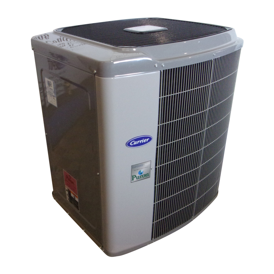
Fig. 1—Model 38TDB
INSTALLATION
Pg 1
8-02
Replaces: 38TDB-3SI
38TDB
A98516
Advertisement
Table of Contents

Related Manuals for Carrier WEATHERMAKERTM TWO-SPEED 38TDB


Summary of Contents for Carrier WEATHERMAKERTM TWO-SPEED 38TDB
- Page 1 Visit www.carrier.com Installation and Start-Up Instructions NOTE: Read the entire instruction manual before starting the installation. This symbol indicates a change since the last issue. SAFETY CONSIDERATIONS Improper installation, adjustment, alteration, service, maintenance, or use can cause explosion, fire, electrical shock, or other conditions which may cause death, personal injury, or property damage.
- Page 2 NOTE: Avoid contact between tubing and structure OUTDOOR WALL INDOOR WALL CAULK INSULATION THROUGH THE WALL HANGER STRAP (AROUND VAPOR TUBE ONLY) 1 MIN. SUSPENSION Fig. 2—Connecting Tubing Installation INSPECT EQUIPMENT File claim with shipping company prior to installation if shipment is damaged or incomplete.
- Page 3 COIL Fig. 4—TXV Installed 8. Install vapor elbow (see Fig. 5B) with equalizer adapter to suction tube of line set and suction connection to indoor coil. Adapter has a 1/4-in. male connector or attaching equalizer tube. 9. Connect equalizer tube of TXV to 1/4-in. equalizer fitting on vapor line adapter.
- Page 4 Do not leave system open to atmosphere any longer than minimum required for installation. POE oil in compressor is extremely susceptible to moisture absorption. Always keep ends of tubing sealed during installation. If ANY refrigerant tubing is buried, provide 6–in. vertical rise at service valve.
- Page 5 5000 4500 4000 3500 3000 2500 2000 1500 1000 MINUTES Fig. 8—Deep Vacuum Graph 5. Repeat this procedure as indicated in Fig. 9. System will then contain minimal amounts of contaminants and water vapor. FINAL TUBING CHECK IMPORTANT: Check to be certain factory tubing on both indoor and outdoor unit has not shifted during shipment.
- Page 6 THERMIDISTAT VARIABLE-SPEED CONTROL CONDENSING TWO-SPEED FURNACE AIR CONDITIONER MODEL RH O/W2 HEAT STAGE 2 COOL STAGE 1 Y1/W2 W/W1 HEAT STAGE 1 W/W1 Y/Y2 Y/Y2 COOL STAGE 2 24 VAC HOT DEHUM JUMPER DHUM DEHUMIDIFY 24 VAC COMM HUMIDIFY HUMIDIFIER (24 VAC) OUTDOOR SENSOR...
- Page 7 PROGRAMMABLE SINGLE-STAGE TWO-SPEED THERMOSTAT FURNACE AIR CONDITIONER MODEL 2S COOL STAGE 1 Y1/W2 HEAT STAGE 1 W/W1 COOL STAGE 2 Y/Y2 O/W2 24 VAC HOT 24 VAC COMM OUTDOOR SENSOR CONNECTION TWO-STAGE NON-PROGRAMMABLE FURNACE WITH THERMOSTAT TWO-SPEED PSC BLOWER MODEL 2S AIR CONDITIONER MOTOR 24 VAC HOT...
- Page 8 PROGRAMMABLE FK4C, FV4A THERMOSTAT TWO-SPEED OR 40FK MODEL 2S AIR CONDITIONER FAN COIL JUMPER 24 VAC HOT COOL STAGE 1 Y1/W2 Y/Y2 COOL STAGE 2 Y/Y2 REMOVE HEAT STAGE 1 W/W1 J2 JUMPER FOR HEAT HEAT STAGE 2 STAGING O/W2 24 VAC COMM OUTDOOR SENSOR...
-
Page 9: Wiring Diagram Notes
WIRING DIAGRAM NOTES: 1. WIRING MUST CONFORM TO NEC OR LOCAL CODES. 2. UNDERLINED LETTER ON THERMOSTAT TERMINAL INDICATES USAGE. FOR EXAMPLE: O/W2 MEANS O IS ENERGIZED IN COOLING MODE. 3. REFER TO INDOOR UNIT INSTALLATION INSTRUCTIONS FOR ANY ADDITIONAL FEATURES AND WIRING INFORMA- TION. - Page 10 A91431 NOTE: Carrier electronic thermostats are equipped with a 15- minute staging timer. This timer prevents the two-speed system from operating at high speed until unit has been operating in low speed for 15 minutes unless there is at least a 5°F difference...
- Page 11 Step 11—Check Charge Service valve gage ports are not equipped with Schrader valves. To prevent personal injury, make sure gage manifold is connected to the valve gage ports before moving valves off fully back seated position. Wear safety glasses and gloves when handling refrigerant.
- Page 12 Table 4—High Capacity Only Subcooling TXV TYPE EXPANSION DEVICE UNIT HIGH CAPACITY ONLY SUBCOOLING AT SERVICE VALVE 14°F 15°F 11°F 12°F 16°F Table 5—Control Function LED Code CODE DEFINITION Constant flash No demand No pause Stand by 1 flash Low-speed operation w/pause 2 flashes High-speed operation...
- Page 13 Table 6—Two-Speed Compressor (Winding Resistance at 70°F ± 20°) WINDING 036–037 Start (S-C) 2.280 1.850 Run (R-C) 0.770 0.745 Compressor Control Contactors Low and high capacity contactor coils are 24 volts. The electronic control board controls the operation of the low speed (C-L) and the high speed (C-H) contactors.
- Page 14 DUAL CAPACITY CONNECTION DIAGRAM 208 / 230 - 1 - 60 POWER SUPPLY EQUIP GND HP/AC FORCED DEFROST DEFROST TIME (MIN) COMM STATUS A B C D TO INDOOR UNIT Fig. 15—Wiring Diagram—024, 036, 048 START YEL/PNK COMP YEL/PNK BLU/PNK BLU/PNK START RELAY...
- Page 15 DUAL CAPACITY CONNECTION DIAGRAM 208 / 230 - 1 - 60 POWER SUPPLY EQUIP GND HP/AC YEL/PNK FORCED YEL/PNK DEFROST BLU/PNK BLU/PNK PWM 2 DEFROST PWM 1 TIME (MIN) COMM STATUS A B C D TO INDOOR UNIT Fig. 16—Wiring Diagram—037 NOTE #10 COMP START...
- Page 16 TIME (MIN) TO INDOOR UNIT Copyright 2002 CARRIER Corp. • 7310 W. Morris St. • Indianapolis, IN 46231 Manufacturer reserves the right to discontinue, or change at any time, specifications or designs without notice and without incurring obligations. Book 1 4 PC 101 Catalog No.
Need help?
Do you have a question about the WEATHERMAKERTM TWO-SPEED 38TDB and is the answer not in the manual?
Questions and answers
how do I clean my 38TDB fan unit outside? Is it necessary and how often?