Advertisement
Quick Links
Visit www.carrier.com
Installation and Start-Up Instructions
NOTE: Read the entire instruction manual before starting the
installation.
This symbol → indicates a change since the last issue.
SAFETY CONSIDERATIONS
Improper installation, adjustment, alteration, service, maintenance,
or use can cause explosion, fire, electrical shock, or other
conditions which may cause death, personal injury, or property
damage. Consult a qualified installer, service agency, or your
distributor or branch for information or assistance. The qualified
installer or agency must use factory-authorized kits or accessories
when modifying this product. Refer to the individual instructions
packaged with the kits or accessories when installing.
Follow all safety codes. Wear safety glasses, protective clothing,
and work gloves. Use quenching cloth for brazing operations.
Have fire extinguisher available. Read these instructions thor-
oughly and follow all warnings or cautions included in literature
and attached to the unit. Consult local building codes and National
Electrical Code (NEC) for special requirements.
Recognize safety information. This is the safety-alert symbol
When you see this symbol on the unit and in instructions or
manuals, be alert to the potential for personal injury.
Understand the signal words DANGER, WARNING, and CAU-
TION. These words are used with the safety-alert symbol. DAN-
GER identifies the most serious hazards which will result in severe
personal injury or death. WARNING signifies hazards which
could result in personal injury or death. CAUTION is used to
identify unsafe practices which would result in minor personal
injury or product and property damage. NOTE is used to highlight
suggestions which will result in enhanced installation, reliability,
or operation.
Before installing, modifying, or servicing system, main elec-
trical disconnect switch must be in the OFF position. There
may be more than 1 disconnect switch. Lock out and tag
switch with a suitable warning label. Electrical shock can
cause personal injury or death.
INSTALLATION RECOMMENDATIONS
1. Locate unit away from windows, patios, decks, and so forth,
where unit-operation sound may disturb customer.
2. Ensure that vapor- and liquid-tube diameters are appropriate to
capacity of unit. (See Table 1.)
3. Run refrigerant tubes as directly as possible by avoiding
unnecessary turns and bends.
4. Leave some slack between structure and unit to absorb
vibration.
5. When passing refrigerant tubes through the wall, seal opening
with RTV or other pliable silicon-based caulk. (See Fig. 3.)
6. Avoid direct tubing contact with water pipes, duct work, floor
joists, wall studs, floors, and walls.
Manufacturer reserves the right to discontinue, or change at any time, specifications or designs without notice and without incurring obligations.
Book 1 4
PC 101
Catalog No. 003-80016
Tab 3a 2a
.
7. Do not suspend refrigerant tubing from joists and studs with a
rigid wire or strap that comes in direct contact with tubing.
(See Fig. 3.)
8. Ensure that tubing insulation is pliable and completely sur-
rounds vapor tube.
9. When necessary, use hanger straps which are 1 in. wide and
conform to shape of tubing insulation. (See Fig. 3.)
10. Isolate hanger straps from insulation by using metal sleeves
bent to conform to shape of insulation.
When outdoor unit is connected to factory-approved indoor unit,
outdoor unit contains system refrigerant charge for operation with
factory-approved indoor unit of the same size when connected by
15 ft (4.57m) of field-supplied tubing. For proper unit operation,
check refrigerant charge using charging information located on
control box cover.
IMPORTANT: Maximum liquid-line size is 3/8-in. (9.53mm)
O.D. for all residential applications including long line.
IMPORTANT: Always install a liquid-line filter drier. Refer to
Product Data Digest for appropriate part number. Obtain filter
driers from your local distributor or branch.
Step 1—Check Equipment and Job Site
UNPACK UNIT
Move to final location. Remove carton, taking care not to damage
unit.
INSPECT EQUIPMENT
File claim with shipping company prior to installation if shipment
is damaged or incomplete. Locate unit-rating plate on unit service
Printed in U.S.A.
Form 38TUA-C4SI
38TUA—50 Hz
Air Conditioning Unit
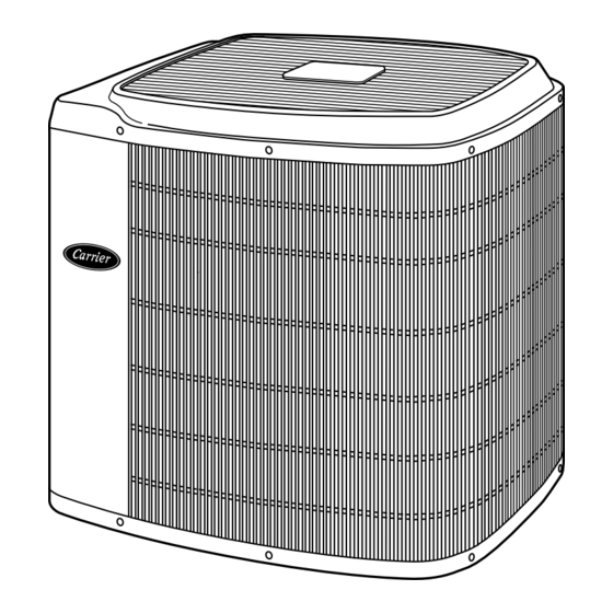
Fig. 1—Model 38TUA
INSTALLATION
Pg 1
12-03
Replaces: 38TUA-C3SI
A98516
Advertisement

Related Manuals for Carrier 38TUA


Summary of Contents for Carrier 38TUA
- Page 1 Electrical Code (NEC) for special requirements. A98516 Recognize safety information. This is the safety-alert symbol Fig. 1—Model 38TUA When you see this symbol on the unit and in instructions or manuals, be alert to the potential for personal injury. 7. Do not suspend refrigerant tubing from joists and studs with a rigid wire or strap that comes in direct contact with tubing.
- Page 2 MINIMUM CIRCUIT AMPS ACCESS MAX OVERCURRENT PROTECTIVE DEVICE PANEL TYPE CANADA MAX FUSE MAX HACR CKT-BKR MAX CKT-BKR IN. DIA LIQUID ® ® LINE CONN CARRIER CORP INDIANAPOLIS IN 313948-401 REV A 46206 A92471 UNIT SIZE 27-1/2 698.5 558.8 8-3/16 207.9 2-13/16 71.4...
-
Page 3: Refrigerant Tubing
→ Table 1—Refrigerant Connections and Recommended Liquid and Vapor Tube Diameters LIQUID VAPOR VAPOR (LONG LINE) UNIT SIZE Connection Diameter Tube Diameter Connection Diameter Tube Diameter Connection Diameter Tube Diameter 9.53 9.53 16.00 16.00 16.00 19.05 9.53 9.53 19.05 19.05 19.05 22.35 9.53... -
Page 4: Connect Control Wiring
Table 2—Accessory Usage REQUIRED FOR REQUIRED FOR REQUIRED FOR LOW-AMBIENT LONG-LINE SEA COAST ACCESSORY APPLICATIONS APPLICATIONS* APPLICATIONS (BELOW 55°F/12.8°C) (OVER 50 FT/15.24M) (WITHIN 2 MILES/3.22KM) Crankcase Heater Evaporator Freeze Thermostat Winter Start Control Yes† Accumulator Compressor Start Assist Capacitor and Relay MotorMaster®... - Page 5 CARRIER CARRIER FA, FB, FC, NON-PROGRAMMABLE NON-PROGRAMMABLE FD, FF SINGLE-STAGE THERMOSTAT THERMOSTAT FAN COIL CONDITIONER MODEL AC FURNACE CONDITIONER MODEL AC 24 VAC HOT 24 VAC HOT 24 VAC COM 24 VAC COM W/W1 HEAT STAGE 1 NOTE 2 NOTE 2...
- Page 6 Y/Y2 A97592 NOTES: 1. CARRIER THERMOSTAT WIRING DIAGRAMS ARE ONLY ACCURATE FOR MODEL NUMBERS BEGINNING WITH TSTAT _ _ _ _ _ _ _. 2. WIRING MUST CONFORM TO NEC OF LOCAL CODES. 3. SOME UNITS ARE EQUIPPED WITH PRESSURE SWITCH(ES), TEMPERATURE SWITCH, OR 5-MINUTE COMPRESSOR CYCLE PROTECTION.
-
Page 7: Sequence Of Operation
To prevent personal injury wear safety glasses, protective clothing, and gloves when handling refrigerant and observe the following: • Back seating service valves are not equipped with Schrader valves. Fully back seat (counter clockwise) valve stem before removing gage port cap. •... -
Page 8: Care And Maintenance
Step 12—Final Checks CARE AND MAINTENANCE IMPORTANT: Before leaving job, be sure to do the following: For continuing high performance and minimize possible equip- 1. Securely fasten all panels and covers. ment failure, periodic maintenance must be performed on this equipment. - Page 9 Table 4—Superheat Charging (English) OUTDOOR EVAPORATOR ENTERING AIR TEMPERATURE (°F WB) TEMP (°F) — — — — — — — — — — — — — — — — — — — — — — — — — — — —...
- Page 10 Table 6—Superheat Charging Table (SI) OUTDOOR EVAPORATOR ENTERING AIR TEMPERATURE (°C WB) TEMP (°C) 11.1 11.9 12.8 14.4 16.1 17.8 19.4 20.6 22.2 23.3 25.0 10.0 10.8 11.7 13.3 15.0 16.7 18.3 20.0 21.1 22.2 23.9 – 10.6 11.7 13.3 15.0 16.7 18.3...
- Page 12 Copyright 2003 CARRIER Corp. • 7310 W. Morris St. • Indianapolis, IN 46231 38tuac4si Manufacturer reserves the right to discontinue, or change at any time, specifications or designs without notice and without incurring obligations. Book 1 4 Tab 3a 2a PC 101 Catalog No.
Need help?
Do you have a question about the 38TUA and is the answer not in the manual?
Questions and answers