
Subscribe to Our Youtube Channel
Related Manuals for TEXIO FGX-2005


Summary of Contents for TEXIO FGX-2005
- Page 1 All manuals and user guides at all-guides.com INSTRUCTION MANUAL Arbitrary Function Generator FGX-2005 FGX-2112 B71-0402-01...
- Page 2 All manuals and user guides at all-guides.com ■ About Brands and Trademarks “TEXIO” is the product brand name of our industrial electronic devices. All company names and product names mentioned in this manual are the trademark or the registered trademark of each company or group in each country and region.
-
Page 3: Table Of Contents
All manuals and user guides at all-guides.com CONTENTS USING THE PRODUCT SAFELY ············································ Ⅰ -Ⅳ 1. GETTING STARTED ................1 1-1. Main Features ................1 1-2. Panel Overview ................2 1-3. Rear Panel ..................5 1-4. Display ................... 6 1-5. Setting up the Function Generator ........... 7 2. - Page 4 All manuals and user guides at all-guides.com 3-9-4. Setting the Carrier Amplitude ..............30 3-9-5. Setting the Modulating Wave Shape............31 3-9-6. Setting the Modulation Frequency (Rate) ..........31 3-9-7. Frequency Deviation .................. 32 3-9-8. Setting the Modulation Source..............33 3-10.
- Page 5 All manuals and user guides at all-guides.com 4-3-4-5. SOURce[1]:SQUare:DCYCle ............... 64 4-3-4-6. SOURce[1]:RAMP:SYMMetry ............. 65 4-3-4-7. OUTPut....................66 4-3-4-8. SOURce[1]:OUTPut:LOAD ..............66 4-3-4-9. SOURce[1]:VOLTage:UNIT ..............66 4-3-5. Amplitude Modulation (AM) Commands ............ 67 4-3-5-1. SOURce[1]:AM:STATe ................ 68 4-3-5-2. SOURce[1]:AM:SOURce ..............68 4-3-5-3.
- Page 6 All manuals and user guides at all-guides.com USING THE PRODUCT SAFELY ■ Preface To use the product safely, read instruction manual to the end. Before using this product, understand how to correctly use it. If you read the manuals but you do not understand how to use it, ask us or your local dealer.
- Page 7 All manuals and user guides at all-guides.com USING THE PRODUCT SAFELY WARNING CAUTION ■ Do not remove the product's covers and panels Never remove the product's covers and panels for any purpose. Otherwise, the user's electric shock or fire may be incurred. ■...
- Page 8 All manuals and user guides at all-guides.com USING THE PRODUCT SAFELY ■ Warning item on Grounding If the product has the GND terminal on the front or rear panel surface, be sure to ground the product to safely use it. ■...
- Page 9 All manuals and user guides at all-guides.com USING THE PRODUCT SAFELY ■ Input / Output terminals Maximum input to terminal is specified to prevent the product from being damaged. Do not supply input, exceeding the specifications that are indicated in the "Rating" column in the instruction manual of the product. Also, do not supply power to the output terminals from the outside.
-
Page 10: Using The Product Safely
The Getting started chapter introduces the function generator’s main features, appearance and introduces a quick instructional summary of some of the basic functions. For comprehensive operation instructions, please see the operation chapter. 1-1. Main Features Model name FGX-2005 FGX-2112 Frequency Range 0.1Hz~5MHz 0.1Hz~12MHz Output waveform... -
Page 11: Panel Overview
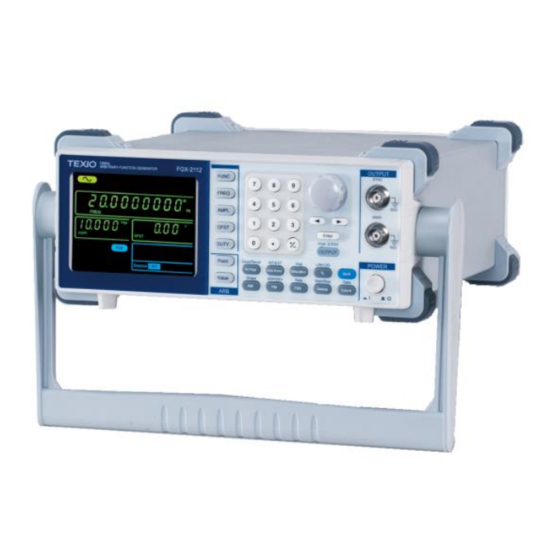
All manuals and user guides at all-guides.com 1-2. Panel Overview FGX-2112 Front Panel Arrow keys SYNC output Number Scroll port Display Wheel OUTPUT OUTPUT Arbitrary Function Generator SYNC FUNC FREQ MAIN AMPL MAIN output port OFST Enter Function High-Z/50Ω DUTY OUTPUT keys POWER... - Page 12 All manuals and user guides at all-guides.com Output control Turns the output on/off. OUTPUT Load Toggles the load impedance between Shift 50Ω and High-Z. Impedance High Z/50Ω OUTPUT Operation keys Selects Hz or Vpp units. Hz/Vpp Save/Recall Saves or recalls waveforms from memory. Shift Hz/Vpp Selects kHz or Vrms units.
- Page 13 All manuals and user guides at all-guides.com Turns the frequency counter on/off*. Count Gate Sets the frequency counter gate time*. Shift Count ARB edit keys Arbitrary waveform editing keys. Point The Point key sets the ARB point numbers. The Value key sets the amplitude value of Value the selected point.
-
Page 14: Rear Panel
50-60Hz 25VA Trigger Power socket Type B USB port Trigger input FGX-2005 Rear Panel WARNING TO AVOID ELECTRIC SHOCK THE POWER CORD PROTECTIVE GROUNDING CONDUCTOR MUST BE CONNECTED TO GROUND. NO OPERATOR SERVICEABLE COMPONENTS INSIDE. DO NOT REMOVE COVERS. REFER SERVICING TO QUALIFIED PERSONNEL. -
Page 15: Display
All manuals and user guides at all-guides.com 1-4. Display Waveform type Counter settings USB icon Frequency display Secondary parameter display Modulation, sweep, counter menu Waveform type Press the function key to cycle through different output waveforms. Counter settings Gate time counter settings*. USB icon Shows the USB interface status. -
Page 16: Setting Up The Function Generator
All manuals and user guides at all-guides.com 1-5. Setting up the Function Generator Background This section describes how adjust the handle and power up the function generator. Adjusting the Pull out the handle OUTPUT OUTPUT Arbitrary Function Generator SYNC FUNC FREQ 50 W stand... - Page 17 All manuals and user guides at all-guides.com The function generator is now ready to be used.
-
Page 18: Quick Reference
All manuals and user guides at all-guides.com 2. QUICK REFERENCE This chapter lists operation shortcuts and default factory settings. Use this chapter as a handy reference for instrument functions. This chapter is to be used as a quick reference; for detailed explanations on parameters, settings and limitations, please see the operation chapter (page 17) or specifications (page 85). -
Page 19: Selecting A Waveform
All manuals and user guides at all-guides.com 4. Press the Enter key to Enter confirm the new parameter value. 5. Alternatively, the number pad can be used to set the value of the selected parameter. 6. To finish editing with the Hz/Vpp number pad, select the unit with one of the unit keys. -
Page 20: Ramp Wave
All manuals and user guides at all-guides.com 5. Press the output key. OUTPUT 2-2-3. Ramp Wave Example: Ramp Wave, 10kHz, 3Vpp, 25% symmetry Output 1. Press the FUNC key FUNC → MAIN repeatedly to select the Ramp wave. 2. Press FREQ > 1 > 0 > FREQ kHz/Vrms 50 W... -
Page 21: Modulation
All manuals and user guides at all-guides.com 2-4. Modulation 2-4-1. AM (FGX-2112 only) Example: AM modulation. 100Hz modulating square wave. 1 Vpp, 1kHz Sine wave carrier. 70% modulation depth. Internal source signal. Output 1. Press the FUNC key FUNC → repeatedly to select the MAIN Sine wave. -
Page 22: Fsk Modulation (Fgx-2112 Only)
All manuals and user guides at all-guides.com 3. Press AMPL > 1 > Vpp. AMPL Hz/Vpp 4. Press FM. INT/EXT 5. Press Shift > INT/EXT > Shift kHz/Vrms select INT source. Shape 6. Press Shift > Shape Shift repeatedly to select →... -
Page 23: Sweep (Fgx-2112 Only)
All manuals and user guides at all-guides.com 7. Press Shift > Hop > 1 > Shift MHz/dBm 0 > Hz. Hz/Vpp 8. Press the OUTPUT key. OUTPUT 9. Press FSK again to deselect the FSK function. 2-5. Sweep (FGX-2112 only) Example: Frequency Sweep. -
Page 24: Counter (Fgx-2112 Only)
All manuals and user guides at all-guides.com 2-6. Counter (FGX-2112 only) Example: Frequency counter function, gate time 1s. Input 1. Press the Count key. Count OUTPUT INPUT Gate 2. Press Shift > Gate Counter Shift Count repeatedly to select the 1S gate time. -
Page 25: Default Settings
All manuals and user guides at all-guides.com 2-8. Default Settings The default settings can be loaded by using the *RST command or pressing the following keys:Duty,1,2,3,4,8,Enter Output Config. Function Sine wave Frequency 1kHz Amplitude 100mVpp Offset 0.00Vdc Output units 50Ω Output terminal 50Ω... -
Page 26: Operation
All manuals and user guides at all-guides.com 3. OPERATION The Operation chapter shows how to output basic waveforms and create ARB waveforms. The FGX-2112 can also perform advanced functions such as modulation, sweep, FSK and counter functions. 3-1. Select a Waveform The FGX-2000 can output four standard waveforms: sine, square, ramp and noise waveforms. -
Page 27: Setting The Amplitude
All manuals and user guides at all-guides.com Range Sine 0.1Hz ~ 12MHz* Square 0.1Hz ~ 12MHz* Ramp 0.1Hz ~ 1MHz *limited to 5MHz for the FGX-2005, 12MHz for the FGX-2112. Example: FREQ = 1kHz 3-3. Setting the Amplitude Panel Operation 1. Press the AMPL key. AMPL 2. -
Page 28: Setting The Dc Offset
All manuals and user guides at all-guides.com Example: AMPL= 1Vpp 3-4. Setting the DC Offset Panel Operation 1. Press the OFST key. OFST 2. The OFST icon will flash in the secondary display area. 3. Use the arrow keys, scroll wheel and Enter →... -
Page 29: Setting The Duty Cycle/Symmetry
All manuals and user guides at all-guides.com 3-5. Setting the Duty Cycle/Symmetry Background The DUTY key sets the duty cycle or symmetry of the standard square or ramp waveforms. Panel Operation 1. Ensure a square or ramp waveform is Page 17 selected. -
Page 30: Setting The Load Impedance
All manuals and user guides at all-guides.com 3-6. Setting the Load Impedance The FGX-2000 load impedance can be set to 50Ω Background or to High-Z. When the load impedance is set to high-Z the effect output is doubled compared to the default 50Ω. -
Page 31: Turning The Output On
All manuals and user guides at all-guides.com 3-7. Turning the Output On High Z/50Ω Panel Operation 1. Press the OUTPUT key to OUTPUT output the selected waveform. The output key will turn green when the output is OUTPUT OUTPUT High Z/50Ω 2. -
Page 32: Am Carrier Waveform
All manuals and user guides at all-guides.com Example: AM activated AM modulation can be deactivated by pressing the AM Note key again. 3-8-2. AM Carrier Waveform Background The FUNC key selects the AM carrier waveform. Sine, square or ramp waveforms can be used as the carrier. The default waveform is set to sine. -
Page 33: Setting The Carrier Amplitude
All manuals and user guides at all-guides.com Range Sine 0.1Hz ~ 12MHz Square 0.1Hz ~ 12MHz Ramp 0.1Hz ~ 1MHz Example: FREQ = 1kHz 3-8-4. Setting the Carrier Amplitude Panel Operation 1. Press AMPL key. AMPL 2. The AMPL icon will flash in the secondary display area. -
Page 34: Setting The Modulating Wave Shape
All manuals and user guides at all-guides.com 3-8-5. Setting the Modulating Wave Shape The FGX-2112 has sine, square and Triangle modulating waveform shapes. Sine waves are the default wave shape. Shape Panel Operation 1. Press the Shift + Shape Shift key repeatedly to select a shape waveform. -
Page 35: Modulation Depth
All manuals and user guides at all-guides.com Range (Internal source) 2mHz ~ 20kHz Default 100Hz Example: Rate= 100Hz 3-8-7. Modulation Depth Modulation depth is the ratio (as a percentage) of the unmodulated carrier amplitude and the minimum amplitude deviation of the modulated waveform. In other words, modulation depth is the maximum amplitude of the modulated waveform compared to the carrier waveform as a percentage. -
Page 36: Setting The Modulation Source
All manuals and user guides at all-guides.com Example: DEP= 100% When the modulation depth is greater than Note 100%, the output cannot exceed ±5VPeak (50Ω load). If an external modulation source is selected, modulation depth is limited to ±5V from the MOD input port on the rear panel. -
Page 37: Frequency Modulation (Fm)(Fgx-2112 )
All manuals and user guides at all-guides.com Example: External MOD AM output input signal MOD input signal 3-9. Frequency Modulation (FM)(FGX-2112 ) An FM waveform is produced from a carrier waveform and a modulating waveform. The instantaneous frequency of the carrier waveform varies with the magnitude of the modulating waveform. -
Page 38: Fm Carrier Waveform
All manuals and user guides at all-guides.com FM modulation can be deactivated by pressing the FM Note key again. 3-9-2. FM Carrier Waveform Background The FUNC key selects the FM carrier waveform. Sine, square or ramp waveforms can be used as the carrier. The default waveform is set to sine. -
Page 39: Setting The Carrier Amplitude
All manuals and user guides at all-guides.com Example: FREQ = 1kHz 3-9-4. Setting the Carrier Amplitude Panel Operation 1. Press AMPL key. AMPL 2. The AMPL icon will flash in the secondary display area. 3. Use the arrow keys, scroll wheel and Enter →... -
Page 40: Setting The Modulating Wave Shape
All manuals and user guides at all-guides.com 3-9-5. Setting the Modulating Wave Shape The FGX-2112 has sine, square and Triangle modulating waveform shapes. Sine waves are the default wave shape. The modulating wave shape is for internal sources only. Shape Panel Operation 1. -
Page 41: Frequency Deviation
All manuals and user guides at all-guides.com Use the keypad and the relevant unit key to enter a Hz/Vpp → new rate. kHz/Vrms Range (Internal source) 2mHz ~ 20kHz Default 100Hz Example: Rate= 100Hz 3-9-7. Frequency Deviation The frequency deviation is the peak frequency deviation from the carrier wave and the modulated wave. -
Page 42: Setting The Modulation Source
All manuals and user guides at all-guides.com The frequency deviation must be equal to or Note less than the carrier frequency. The sum of the carrier frequency and frequency deviation must be less than or equal to the maximum carrier. The maximum frequency deviation allowed will be limited by the set carrier frequency. -
Page 43: Frequency Shift Keying (Fsk) Modulation (Fgx-2112 )
All manuals and user guides at all-guides.com the deviation frequency. For example: if the deviation frequency is set to 1kHz, an input voltage of +5V will increase the frequency to 1kHz, whilst an input voltage of -5V will reduce the frequency below that of the carrier by 1kHz. -
Page 44: Selecting Fsk Modulation
All manuals and user guides at all-guides.com 3-10-1. Selecting FSK Modulation Panel Operation 1. Press the FSK key. 2. The modulation, sweep and counter menu display will appear. The FSK icon indicates that the FSK function is active. Example: FSK activated FSK modulation can be deactivated by pressing the FSK Note key again. -
Page 45: Setting The Carrier Amplitude
All manuals and user guides at all-guides.com 2. The FREQ icon will flash in the frequency display area. 3. Use the arrow keys, scroll wheel and Enter key to edit Enter → the frequency. Use the keypad and the Hz/Vpp relevant unit key to enter a →... -
Page 46: Setting The Hop Frequency
All manuals and user guides at all-guides.com Use the keypad and the Hz/Vpp relevant unit key to enter a → new amplitude. kHz/Vrms MHz/dBm Range No Load 2mVpp~20Vpp 50Ω Load 1mVpp~10Vpp Example: AMPL= 1Vpp 3-10-5. Setting the Hop Frequency The default Hop frequency for all waveform shapes is 100 Hz. A square wave with a duty cycle of 50% is used for the internal modulation waveform. -
Page 47: Fsk Rate
All manuals and user guides at all-guides.com Ramp 0.1Hz ~ 1MHz Default 100Hz Example: Hop = 100Hz 3-10-6. FSK Rate FSK Rate function is used to determine the rate at which the output frequency changes between the carrier and hop frequencies. The FSK Rate function only applies to internal FSK sources. -
Page 48: Setting The Fsk Source
All manuals and user guides at all-guides.com 3-10-7. Setting the FSK Source The FGX-2000 accepts internal and external FSK sources, with internal as the default source. When the FSK source is set to internal, the FSK rate is configured using the FSK Rate function. When an external source is selected the FSK rate is equal to the frequency of the Trigger input signal on the rear panel. -
Page 49: Frequency Sweep (Fgx-2112 )
All manuals and user guides at all-guides.com 3-11. Frequency Sweep (FGX-2112 ) The function generator can perform a sweep for sine, square or ramp waveforms, but not noise, and ARB. In Sweep mode, the function generator will sweep from a start frequency to a stop frequency over a number of designated steps. -
Page 50: Setting Start And Stop Frequency
All manuals and user guides at all-guides.com 3-11-2. Setting Start and Stop Frequency The start and stop frequencies define the upper and lower sweep limits. The function generator will sweep from the start through to the stop frequency and cycle back to the start frequency. The sweep is phase continuous over the full sweep range. -
Page 51: Sweep Mode
All manuals and user guides at all-guides.com Example: Stop = 1kHz 3-11-3. Sweep Mode Sweep mode is used to select between linear or logarithmic sweeping. Linear sweeping is the default setting. LIN/LOG Panel Operation 1. Press the Shift + LIN/LOG Shift key to select linear (LINS) or logarithmic (LOGS) -
Page 52: Setting The Sweep Source (Trigger)
All manuals and user guides at all-guides.com 3. Use the arrow keys, scroll wheel → Enter and Enter key to edit the rate. Use the keypad and the relevant Hz/Vpp → unit key to enter a kHz/Vrms new rate. Range Sweep Rate 1kHz ~ 2mHz (1ms ~ 500s) Default... -
Page 53: Creating An Arbitrary Waveform
All manuals and user guides at all-guides.com Connection For external sources, connect the OUTPUT INPUT Counter (EXT source Sweep trigger signal to the only) Trigger input port on the rear panel. Trigger Example: Source = EXT With an external source, a sweep is output each time a Note trigger pulse (TTL) is received from the Trigger input port on the rear panel. - Page 54 All manuals and user guides at all-guides.com 4. Use the scroll wheel or keypad to choose a point number. Use the Enter key to Enter confirm the point number. Range Point: 0 ~ 4096 5. Press the Value key. Point 6.
-
Page 55: Using The Frequency Counter
All manuals and user guides at all-guides.com 3-13. Using the Frequency Counter 3-13-1. Selecting the Frequency Counter Function Connection Connect the signal source to Counter input OUTPUT INPUT Counter port on the rear panel. Trigger Gate Panel Operation 1. Press the Count key. Count 2. -
Page 56: Using The Sync Output Port
All manuals and user guides at all-guides.com 3-14. Using the SYNC Output Port 3-14-1. Connecting the SYNC Output Port Background The SYNC output port is used as a synchronization signal for function outputs. All the output signals apart from the noise output function have a synchronization signal. - Page 57 All manuals and user guides at all-guides.com Output diagram Ramp wave output SYNC output SYNC Output SYNC output: A single TTL positive pulse at the start of For ARB Wave each ARB period (pulse width = 1/sample rate). Output diagram ARB output SYNC output SYNC Output...
-
Page 58: Save And Recall State/Arb Waveform
All manuals and user guides at all-guides.com SYNC Output SYNC output: TTL square waveform with a 50% duty For FSK cycle. The SYNC output is at a logically high level when the modulated output is positive (The SYNC output is synchronized to the modulated output frequency). - Page 59 All manuals and user guides at all-guides.com 3. Use the scroll wheel or keypad to choose the save/recall number. Use the Enter key to save/recall the state. Enter The instrument state can be saved to any 10 (0~9) of the Note storage locations.
-
Page 60: Remote Interface
Serial number, and Firmware version in the following format. TEXIO, FGX-2112, SN:XXXXXXXX,Vm.mm ^j and ^m can be used as the terminal character when Note using a terminal program. PC Software The proprietary PC software, downloadable from TEXIO website, can be used to download waveforms. -
Page 61: Command Syntax
All manuals and user guides at all-guides.com 4-2. Command Syntax • Compatible IEEE488.2, 1992 (fully compatible) • standard SCPI, 1994 (partially compatible) Command Tree The SCPI standard is an ASCII based standard that defines the command syntax and structure for programmable instruments. - Page 62 All manuals and user guides at all-guides.com Command forms Commands and queries have two different forms, long and short. The command syntax is written with the short form of the command in capitals and the remainder (long form) in lower case. long long SOURce1:DCOffset...
- Page 63 All manuals and user guides at all-guides.com <NR1> integers 0, 1, 2, 3 <NR2> decimal numbers 0.1, 3.14, 8.5 <NR3> floating point 4.5e-1, 8.25e+1 <NRf> any of NR1, 2, 3 1, 1.5, 4.5e-1 <NRf+> NRf type with a 1, 1.5, 4.5e-1 <Numeric>...
- Page 64 All manuals and user guides at all-guides.com Semicolon (;) A semicolon can be used to combine commands from different node levels. For example: SOURce1:PWM:SOURce? SOURce:PULSe:WIDTh? →SOURce1:PWM:SOURce?;SOURce: PULSe:WIDTh? Comma (,) When a command uses multiple parameters, a comma is used to separate the parameters.
-
Page 65: Command List
All manuals and user guides at all-guides.com 4-3. Command List 4-3-1. System Commands ................... 57 4-3-2. Status Register Commands ............... 57 4-3-2-1. *CLS ....................... 57 4-3-3. APPLy Commands ..................57 4-3-3-1. SOURce[1]:APPLy:SINusoid ..............59 4-3-3-2. SOURce[1]:APPLy:SQUare ..............59 4-3-3-3. SOURce[1]:APPLy:RAMP ..............59 4-3-3-4. -
Page 66: System Commands
Query Syntax IDN? Return <string> parameter Query Example *IDN? > TEXIO,FGX-2005,SN:XXXXXXXX,Vm.mm Returns the identification of the function generator. 4-3-1-2. *RST Description Reset the function generator to its factory default state. Note the *RST command will not delete instrument save Note states/ARB waveforms in memory. - Page 67 Not applicable Not applicable User (ARB) 0.1Hz 12MHz *The FGX-2005 is limited to 5MHz. Output When setting the amplitude, MINimum, MAXimum and Amplitude DEFault can be used instead of specifying an amplitude. The range depends on the function being used. The default amplitude for all functions is 100 mVpp (into 50Ω).
-
Page 68: Source[1]:Apply:sinusoid
[,<offset>] ]] Parameter <frequency> 0.1Hz~12MHz* 1mV~10Vpp (50Ω) <amplitude> -5V ~ +5V (50Ω) <offset> *FGX-2005 limited to 5MHz. Example SOURce1:APPL:SIN MAX, 3.0, -2.5 Outputs a 3Vpp sine wave at 12MHz (max frequency) with a -2.5V offset. 4-3-3-2. SOURce[1]:APPLy:SQUare Description Outputs a square wave when the command has executed. -
Page 69: Source[1]:Apply:noise
Parameter <frequency> 0.1Hz~12MHz* 1mV~10V (50Ω) <amplitude> -5V ~ +5V (50Ω) <offset> *FGX-2005 limited to 5MHz. Example SOURce1:APPL:NOIS DEF, 5.0, 2.0 Sets the amplitude to 5 volts with an offset of 2 volts. 4-3-3-5. SOURce[1]:APPLy:USER Description Outputs an arbitrary waveform that is specified from the FUNC:USER command. -
Page 70: Source[1]:Apply
All manuals and user guides at all-guides.com 4-3-3-6. SOURce[1]:APPLy? Query Description Outputs a string with the current settings. The returned string can be passed back, when appended Note to the APPLy Command. This is intended to be used to return the function generator to a known state. I.e., SOURce[1]:APPL:<passed back string>... -
Page 71: Source[1]:Frequency
Noise Not applicable User 0.1Hz~12MHz* *FGX-2005 limited to 5MHz. If the function mode is changed and the current frequency setting is not supported by the new mode, the frequency setting will be altered to the next highest value. The duty cycle of square waveforms depends on the frequency settings: 1% to 99% (frequency <... -
Page 72: Source[1]:Amplitude
All manuals and user guides at all-guides.com If the frequency is changed and the set duty cycle cannot support the new frequency, the highest duty cycle available at that frequency will be used. A “-221” error will be generated from the remote terminal. Syntax SOURce[1]:FREQuency {<frequency>|MINimum|MAXimum}... -
Page 73: Source[1]:Dcoffset
All manuals and user guides at all-guides.com Query Example SOUR1:AMPL? MAX >+5.0000E+00 The maximum amplitude that can be set for the current function is 5 volts. 4-3-4-4. SOURce[1]:DCOffset Query Description Sets or queries the DC offset for the current mode. The offset parameter can be set to MINimum or MAXimum. -
Page 74: Source[1]:Ramp:symmetry
All manuals and user guides at all-guides.com For square waveforms, the APPLy command and AM/FM modulation modes ignore the duty cycle settings. Syntax SOURce[1]:SQUare:DCYCle {< percent> |MINimum|MAXimum} Example SOUR1:SQU:DCYC MAX Sets the duty cycle to the highest possible for the current frequency. -
Page 75: Output
All manuals and user guides at all-guides.com 4-3-4-7. OUTPut Query Description Enables/Disables or queries the front panel output. The default is set to off. Syntax OUTPut {OFF|ON} Example OUTP ON Turns the output on. Query Syntax OUTPut? Return Parameter Query Example OUTP? >1 The output is currently on. -
Page 76: Amplitude Modulation (Am) Commands
All manuals and user guides at all-guides.com unit is specifically used for a command, such as those used with the APPLy commands. Syntax SOURce[1]:VOLTage:UNIT {VPP|VRMS|DBM} Example SOUR1:VOLT:UNIT VPP Sets the amplitude units to Vpp. Query Syntax SOURce[1]:VOLTage:UNIT? Return Parameter VRMS Vrms Query Example SOUR1:VOLT:UNIT? >VPP... -
Page 77: Source[1]:Am:state
All manuals and user guides at all-guides.com 4-3-5-1. SOURce[1]:AM:STATe Query Description Sets or disables AM modulation. By default AM modulation is disabled. AM modulation must be enabled before setting other parameters. As only one mode is allowed at any one time, other Note modulation modes (inc. -
Page 78: Source[1]:Am:internal:function
All manuals and user guides at all-guides.com 4-3-5-3. SOURce[1]:AM:INTernal:FUNCtion Query Description Sets the shape of the modulating waveform from sine, square or ramp. The default shape is sine. Square waveforms have a 50% duty cycle. Ramp Note waveforms have a symmetry of 100%. Syntax SOURce[1]:AM:INTernal:FUNCtion {SINusoid|SQUare| RAMP }... -
Page 79: Frequency Modulation (Fm) Commands
All manuals and user guides at all-guides.com The function generator will not output more than ±5V, Note regardless of the modulation depth. The modulation depth of an external source is controlled using the ±5V MOD input port on the rear panel, and not the SOURce[1]:AM:DEPTh command. -
Page 80: Source[1]:Fm:state
All manuals and user guides at all-guides.com 4-3-6-1. SOURce[1]:FM:STATe Query Description Sets or disables FM modulation. By default FM modulation is disabled. FM modulation must be enabled before setting other parameters. As only one mode is allowed at any one time, other modes Note (AM, FSK, Sweep etc.) will be disabled when FM modulation is enabled. -
Page 81: Source[1]:Fm:internal:frequency
All manuals and user guides at all-guides.com Square waveforms have a 50% duty cycle. Ramp Note waveforms have a symmetry of 100%. Syntax SOURce[1]:FM:INTernal:FUNCtion {SINusoid|SQUare|RAMP } Example SOUR1:FM:INT:FUNC SIN Sets the FM modulating wave shape to sine. Query Syntax SOURce[1]:FM:INTernal:FUNCtion? Return Sine Parameter... -
Page 82: Frequency-Shift Keying (Fsk) Commands
All manuals and user guides at all-guides.com The relationship of peak deviation to modulating frequency Note and carrier frequency is shown below. Peak deviation = modulating frequency – carrier frequency. The carrier frequency must be greater than or equal to the peak deviation frequency. -
Page 83: Source[1]:Fskey:state
All manuals and user guides at all-guides.com 4. Set the hop frequency using the SOURce[1]:FSK:FREQ command. Select FSK 5. Use the SOURce[1]: FSK:INT:RATE command to set HOP Frequency the FSK rate. The FSK rate can only be set for internal sources. Set FSK Rate 4-3-7-1. -
Page 84: Source[1]:Fskey:frequency
Note duty cycle of 50%. Syntax SOURce[1]:FSKey:FREQuency {<frequency>|MINimum|MAXimum} Parameter <frequency> 0.1Hz~ 12MHz* 0.1Hz~ 1MHz (Ramp) * FGX-2005 limited to 5MHz. Example SOUR1:FSK:FREQ +1.0000E+02 Sets the FSK hop frequency to 100Hz. Query Syntax SOURce[1]:FSKey:FREQuency? [MINimum|MAXimum] Return <NR3> Returns the frequency in Hz. -
Page 85: Frequency Sweep Commands
All manuals and user guides at all-guides.com 4-3-8. Frequency Sweep Commands Below shows the order in which commands must be executed to perform a sweep. Enable Sweep 1. Turn on Sweep mode using the Mode SOURce[1]: SWE:STAT ON command. 2. Use the APPLy command to select the waveform shape. -
Page 86: Source[1]:Frequency:start
All manuals and user guides at all-guides.com 4-3-8-2. SOURce[1]:FREQuency:STARt Query Description Sets the start frequency of the sweep. 100Hz is the default start frequency. To sweep up set the stop frequency higher than the start Note frequency. Set the stop frequency lower than the start frequency to sweep down. -
Page 87: Source[1]:Sweep:spacing
All manuals and user guides at all-guides.com 4-3-8-4. SOURce[1]:SWEep:SPACing Query Description Sets linear or logarithmic sweep spacing. The default spacing is linear. Syntax SOURce[1]:SWEep:SPACing {LINear|LOGarithmic} Example SOUR1:SWE:SPAC LIN Sets the spacing to linear. Query Syntax SOURce[1]:SWEep:SPACing? Return Linear spacing Parameter Logarithmic spacing Query Example SOUR1:SWE:SPAC? >LIN... -
Page 88: Frequency Counter Commands
All manuals and user guides at all-guides.com If EXTernal is selected, the trigger period must be greater Note than the sweep time + 125nS. Syntax SOURce[1]: SWEep:SOURce {IMMediate|EXTernal } Example SOUR1: SWE:SOUR EXT Sets the sweep source to external. Query Syntax SOURce[1]: SWEep:SOURce? Return Immediate... -
Page 89: Counter:value
All manuals and user guides at all-guides.com Return Counter function is off. Parameter Counter function is on. Query Example COUN:STAT? >1 Counter is on. 4-3-9-3. COUNter:VALue? Query Description Queries the counter frequency. The counter function is only applicable for the FGX-21XX Note models. -
Page 90: Source[1]:Function User
All manuals and user guides at all-guides.com 4-3-10-1. SOURce[1]:FUNCtion USER Query Description Use the SOURce[1]:FUNCtion USER command to output the arbitrary waveform currently selected in memory. The waveform is output with the current frequency, amplitude and offset settings. The query returns the current output. Syntax SOURce[1]:FUNCtion USER Example... -
Page 91: Save And Recall Commands
All manuals and user guides at all-guides.com represent waveform data (16 bit integer). Therefore the number of bytes is always twice the number of data points. In the example above, the data block represents 8 data points. Syntax DATA:DAC VOLATILE, 0,{<binary block>|<value>, <value>, . - Page 92 All manuals and user guides at all-guides.com Parameter Recall state 10~19 Recall ARB data Example *RCL 0 Recall the instrument state from memory location 0 (assuming location 0 has been previously saved).
-
Page 93: Appendix
All manuals and user guides at all-guides.com 5. APPENDIX 5-1. Error Messages The FGX-2000 has a number of specific error codes. If a setting error occurs whilst using the function generator, an error message will be momentarily displayed on the screen. Error code Description Frequency forced duty cycle change. -
Page 94: Fgx-2000 Series Specifications
The specifications apply when the function generator is powered on for at least 30 minutes under +20°C~+30°C. to apply the 50Ω load. pecifications Unless otherwise specified, the s models FGX-2005 FGX-2112 Waveforms Sine, Square, Ramp, Noise, ARB Arbitrary Functions Sample Rate... - Page 95 All manuals and user guides at all-guides.com Sine wave Characteristics –55 dBc Harmonic distortion ~ 200kHz, Ampl > 0.1Vpp –50 dBc 200kHz ~ 1MHz, Ampl > 0.1Vpp –35 dBc 1MHz ~ 5MHz, Ampl > 0.1Vpp –30 dBc 5MHz ~ 12MHz, Ampl >...
- Page 96 All manuals and user guides at all-guides.com — Accuracy Time Base accuracy±1count — ±20ppm (23˚C ±5˚C) Time Base after 30 minutes warm up — Resolution The maximum resolution is: 100nHz for 1Hz, 0.1Hz for 100MHz. — 1kΩ/1pf Input Impedance — Sensitivity 35mVrms ~ 30Vms (5Hz to 150MHz)
-
Page 97: External Dimensions Figure
All manuals and user guides at all-guides.com 5-3. External Dimensions Figure... - Page 98 All manuals and user guides at all-guides.com 7F Towa Fudosan Shin Yokohama Bldg., 2-18-13, Shin Yokohama, Kohoku-ku, Yokohama, Kanagawa, 222-0033, Japan. http://www.texio.co.jp/...
Need help?
Do you have a question about the FGX-2005 and is the answer not in the manual?
Questions and answers