
Related Manuals for TEXIO ASR Series


Summary of Contents for TEXIO ASR Series
- Page 1 INSTRUCTION MANUAL AC/DC POWER SOURCE ASR SERIES ASR501-351 ASR102-351 ASR501-351G ASR102-351G B71-0497-01...
- Page 2 ■ About Brands and Trademarks “TEXIO” is the product brand name of our industrial electronic devices. All company names and product names mentioned in this manual are the trademark or the registered trademark of each company or group in each country and region.
-
Page 3: Table Of Contents
CONTENTS GETTING STARTED ..........1 1-1. ASR Series Overview ........1 1-1-1. Series lineup ..............1 1-1-2. Operating Area ..............2 1-1-3. Main Features ..............4 1-1-4. Accessories ..............5 1-2. Appearance ..........6 1-2-1. Front Panel ..............6 1-2-2. Rear Panel ..............11 1-2-3. - Page 4 2-2. Menu Tree ..........45 2-2-1. Main Page ..............46 2-2-2. Function Keys ..............47 2-2-3. Menu ................49 Basic Operation ..........50 3-1. Basic setting ..........50 3-1-1. Select the Output Mode ........... 50 3-1-2. Select the Voltage Range ..........51 3-1-3.
- Page 5 4-2-3. EXT Sync - AC+DC-Sync and AC-Sync mode ....98 4-3. Arbitrary Waveform ........99 4-3-1. Compiling Arbitrary Waveform Input ......99 4-3-2. Manage Arbitrary Waveform Settings ......106 MISCELLANEOUS ..........109 5-1. T Ipeak, hold..........109 5-2. IPK CLR ........... 110 5-3.
- Page 6 7-1-1. Configure Ethernet Connection ........156 7-1-2. USB Remote Interface ..........158 7-1-3. USB Remote Control Function Check ......159 7-1-4. RS-232C Remote Interface (G type) ......160 7-1-5. RS-232C Remote Control Function Check....162 7-1-6. Using Realterm to Establish a Remote Connection ..163 7-1-7.
- Page 7 USING THE PRODUCT SAFELY ■ Preface To use the product safely, read instruction manual to the end. Before using this product, understand how to correctly use it. If you read the manuals but you do not understand how to use it, ask us or your local dealer. After you read the manuals, save it so that you can read it anytime as required.
- Page 8 USING THE PRODUCT SAFELY WARNING CAUTION ■ Do not remove the product's covers and panels Never remove the product's covers and panels for any purpose. Otherwise, the user's electric shock or fire may be incurred. ■ Warning on using the product Warning items given below are to avoid danger to user's body and life and avoid the damage or deterioration of the product.
- Page 9 USING THE PRODUCT SAFELY ■ Warning item on Grounding If the product has the GND terminal on the front or rear panel surface, be sure to ground the product to safely use it. ■ Warnings on Installation environment ● Operating temperature and humidity Use the product within the operating temperature indicated in the “rating”...
- Page 10 USING THE PRODUCT SAFELY ■ Input / Output terminals Maximum input to terminal is specified to prevent the product from being damaged. Do not supply input, exceeding the specifications that are indicated in the "Rating" column in the instruction manual of the product. Also, do not supply power to the output terminals from the outside.
-
Page 11: Getting Started
1. GETTING STARTED This chapter describes the ASR series power supply in a nutshell, including its main features and front / rear panel introduction. 1-1. ASR Series Overview 1-1-1. Series lineup The ASR series consists of 4 models, the ASR501-351, ASR102- 351, ASR501-351G and ASR102-351G, differing only in capacity and interface. -
Page 12: Operating Area
1-1-2. Operating Area ASR501-351(G)AC Mode Output Operating Area ASR501-351(G)DC Mode Output Operating Area... - Page 13 ASR102-351(G)AC Mode Output Operating Area ASR102-351(G)DC Mode Output Operating Area...
-
Page 14: Main Features
1-1-3. Main Features • Performance Maximum AC output voltage is 350 Vrms • Maximum DC output voltage is 500 Vdc • Maximum output frequency is 999.9 Hz in AC mode • Supported AC+DC waveform application • DC full capacity output ability •... -
Page 15: Accessories
1-1-4. Accessories Before using the ASR power source unit, check the package contents to make sure all the standard accessories are included. Standard Part number Description Accessories CD ROM User manual, programming manual Region dependent Power cord 63SC-XF101601 x 1 Mains terminal cover set 63SC-XF101701 x 1 Remote sensing cover set... -
Page 16: Appearance
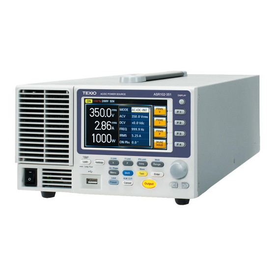
1-2. Appearance 1-2-1. Front Panel Ⓚ ③ ⑦ ⑧ ⑨ Ⓐ ④ ⑤ Ⓘ Ⓙ Ⓕ Ⓖ Ⓗ ① ⑥ Ⓛ ② Ⓑ Ⓒ Ⓓ Ⓔ Item Index Description Power switch button USB interface connector (A Type) LCD screen Display mode select key Function keys (blue zone) Lock/Unlock button V/V-Limit button... - Page 17 Range key/Output mode key Menu key/On phase key Shift key Test key/Output waveform key Enter key Preset key/Local mode key Cancel key/ALM CLR key Output key Scroll wheel Arrow keys Air inlet Hardcopy key...
- Page 18 Item Description Power Turn on the mains power Switch USB A Port The USB port is used for data transfers and upgrading software. Also, it is available for screenshot hardcopy in association with the Hardcopy key. Usable USB flash drive is format type FAT32, up to 32GB.
- Page 19 Used for setting the output voltage V-Limit Used for setting the output voltage limit value Used for setting the output frequency (DC mode N/A) F-Limit Used for setting the output frequency limit value (DC mode N/A) Irms Used for setting the maximum output current IPK-Limit Used to set the peak output current...
- Page 20 Used to navigate menu items or for Wheel increment/decrement values one step at a time. Arrow Keys The arrow keys are used to select the digit power of a value that is being edited Air Inlet Air inlet for cooling the inside of the ASR series...
-
Page 21: Rear Panel
1-2-2. Rear Panel ASR501-351G/102-351G ⑦ ③ ⑦ ③ ⑦ ③ ⑧ ⑧ ⑧ ② ② ② ⑤ ⑤ ⑤ ⑨ ⑨ ⑨ ④ ④ ④ ⑥ ⑥ ⑥ Ⓐ Ⓐ Ⓐ ① ① ① ASR-501-351/102-351 Item Index Description Line input Output terminal Remote sensing input terminal... - Page 22 Exhaust fan External I/O connector External signal input/ External synchronized signal input USB interface connector (B Type) Ethernet (LAN) connector Optional 1 interfaces (RS-232C & GP-IB connectors) Item Description Line Input AC inlet Output Output voltage terminal (M3 screw Terminal type, 10 ~ 18 AWG) Remote Compensation of load wire voltage...
- Page 23 External Used to control ASR externally by Control I/O using the logic signal and monitor Connector Sequence function status External Synchronizing the output frequency Signal with this external input signal for Input SYNC or outputting the amplified external signal with this external Connector input signal for EXT and ADD.
- Page 24 GP-IB The optional GP-IB connector for Connector controlling the ASR remotely (G type)
-
Page 25: Status Bar Icons
1-2-3. Status Bar Icons Status bar Status bar Indicates if the output is ON or OFF. Indicates the output power as a percentage of full scale. Indicates if the output range is 100V, 200V or AUTO. Indicates if the output waveform is Sine, Square, Triangle or ARB 1 - 16. -
Page 26: Theory Of Operation
1-3. Theory of Operation The theory of operation chapter describes the basic principles of operation, protection modes and important considerations that must be taken into account before use. 1-3-1. Glossary Rate Output The maximum value of the output power Maximum capacity will be provided consecutively when the Power Capacity following situations exist:... - Page 27 Maximum Peak The maximum value of the output current (peak Current (AC-INT value) will be provided consecutively to a mode only) capacitor input-type rectifying load when the following situations exist: Output voltage is 100 to 175 V within the 100 V range or 200 to 350 V within the 200 V range.
-
Page 28: Alarms
100%. 1-3-2. Alarms The ASR series have a number of protection features. When one of the protection alarms is tripped, the ALM icon on the display will be lit and the type of alarm that has been tripped will be shown on the display. - Page 29 F-Limit Frequency limit protection prevents a high frequency from damaging the DUT. This alarm can be set by the user. Over current protection prevents high current from damaging the DUT. This alarm can be set by the user. Over temperature protection for power stage board.
-
Page 30: Considerations
1-3-3. Considerations The following situations should be taken into consideration when using the power supply. When the power supply switch is first turned on, Inrush Current an inrush current is generated. Ensure there is enough power available for the power supply when first turned on, especially if a number of units are turned on at the same time. - Page 31 Inductive Load Ensure the connected diode meets the following specifications between the load, CAUTION either capacitor or inductor, and the ASR series power supplies. ✓ Maximum reverse voltage: 600 V or higher ✓ Maximum forward current: 15 A or more for 100V range, and 7.5 A or more for 200V...
-
Page 32: Grounding
1-3-4. Grounding The output terminals of the ASR series are isolated with respect to the protective grounding terminal. The insulation capacity of the load, the load cables and other connected devices must be taken into consideration when connected to the protective ground or when floating. -
Page 33: Operation
2. OPERATION 2-1. Set Up 2-1-1. Power Up Steps 1. Connect the power cord to the rear panel socket. 2. Press the POWER key. The splash screen will appear momentarily before the continuous mode screen appears with the settings loaded. The power supply takes around 15 seconds to fully turn on and shutdown. -
Page 34: How To Use The Instrument
2-1-2. How to Use the Instrument The ASR AC power supplies generally use the Background scroll wheel, Arrow keys and Enter keys to edit numerical values or to select menu options. Menu navigation is performed using the menu keys and function keys on the front panel. The following section will explain some of these concepts in detail. - Page 35 Using the Arrow Use the Arrow keys to select a digit power and Keys and Scroll then use the scroll wheel to edit the value by Wheel to Edit that power. Parameter Values 1. Use the Arrow keys to move the cursor to the digit of the desired value.
- Page 36 Using the The function keys are quick settings keys, the function of which depends on the current menu Function Keys or operation. 1. Press the Function key that corresponds to the setting directly to its left side. 2. The setting or parameter is immediately executed.
-
Page 37: Output Terminals
2-1-3. Output Terminals The output terminals can be output from the rear Background panel. The outputs are limited to 5 A / 2.5 A (ASR501-351(G)), 10 A / 5 A (ASR102-351 (G)). Dangerous voltages. Ensure that the power to WARNING the instrument is disabled before handling the power supply output terminals. - Page 38 4. Cover the protective lid onto the output terminals as the figure below shown. 5. Fasten the screw of protective lid with the unit. 6. Turn the power on. The AC power supply is now ready to power the DUT.
- Page 39 Grounded Neutral Output: ASR allows for a grounded return on the neutral CAUTION output. It is suit for the medical industry that required between ground with neutral is 0 V essentially. And possible to mitigate ground loops that is ideal for reduce ground noise and isolate sensitive equipment from the effects of ground loops.
-
Page 40: Installing Get-003 Box Series
2-1-4. Installing GET-003 Box Series There are optional box series which are Background applicable to the ASR for additional power output socket in the front panel. Optional GET-003 Universal Socket Modules Dangerous voltages. Ensure that the power to WARNING the instrument is disabled before handling the GET-003 installation. - Page 41 3. Align the 2 hooks of GET-003 with the 2 rectangular grooves on the flank of ASR unit and slide GET-003 horizontally. 4. Gently slide the GET-003 into place until click to have it level with ASR evenly. 5. Fasten the 2 screws in the rear side of GET-003 with bare hands easily.
- Page 42 6. Connect the output AC power wires from the GET-003 to the AC output terminals. Red → Line (L) • Black → Neutral (N) • Green → GND ( ) • 7. Cover the protective lid back to the output terminals followed by fastening the screw of protective lid with the unit.
- Page 43 Front Panel 9. Insert the plug from the DUT into the socket. Output Connection For the front panel output, the maximum output CAUTION voltage is 250 VAC and current is 10 A. Dangerous voltages. Ensure output is off WARNING before unplugging the plug from the front panel socket.
-
Page 44: Using The Rack Mount Kit
Background Mount kits, respectively. Unit Model Rack Mount kit part number ASR series GRA-439-E GRA-439-J The GRA-439-E is designed to fit into an EIA rack of 3U-height, while the GRA-439-J is designed to fit into a JIS rack of 3U-height. - Page 45 GRA-439-J Series GRA-439-J Rack Mount Diagram GRA-439-J Rack Mount Diagram Ensure adequate ventilation is provided when using the rack mount. Ensure that a gap is CAUTION given for air intakes. Failure to do so may cause the instrument to overheat.
-
Page 46: Reset To Factory Default Settings
2-1-6. Reset to Factory Default Settings The default settings can be restored from the Background Menu key settings. See page 179 for the default factory settings. Steps 1. Press the Menu key. The Menu settings will appear on the display. 2. -
Page 47: View Firmware Version And Serial Number
2-1-7. View Firmware Version and Serial Number The Menu>System Information setting displays Background the serial number and firmware version. Steps 1. Press the Menu key. The Menu setting will appear on the display. 2. The system information should now be listed in the item 1, System Information, on the display 3. -
Page 48: Lcd Configuration
2-1-8. LCD Configuration The LCD Configuration setting sets the Background brightness, contrast and saturation level of the LCD display. Steps 1. Press the Menu key. The Menu settings will appear on the display. 2. Use the scroll wheel to go to item 7, LCD Configuration and press Enter. -
Page 49: Usb Driver Installation
If the USB Type B interface is to be used for Background remote control, the USB driver needs to be installed. The USB driver, texio_cdc_205.inf, can be downloaded from the TEXIO website. CAUTION For information on the USB interface, see page 158. Steps 1. - Page 50 4. From the hardware wizard choose Browse my computer driver software. 5. Set the file path to the location of the USB driver, click Next and finish the driver installation. 6. ASR will now be located in the Ports node of the hardware tree in the Windows Device Manager if the driver installation was successful.
-
Page 51: Air Filter Installation
2-1-10. Air filter Installation The ASR has the air filter (Part number, ASR- Background 001) that must first be inserted under the control panel before operation. Steps 1. Loose the screw embedded beneath the air inlet as indicated within the figure below. 2. - Page 52 4. The air filter is positioned in the rear side of frame of air inlet. Simply rinse it or replace the filter with a new one based on the actual status. 5. Repeat the previous steps conversely to reinstall the air inlet with new filter back to unit. 6.
-
Page 53: Wire Gauge Considerations
2-1-11. Wire Gauge Considerations Before connecting the output terminals to a load, Background the wire gauge of the cables should be considered. It is essential that the current capacity of the load cables is adequate. The rating of the cables must equal or exceed the maximum current rated output of the instrument. - Page 54 environments. Where shielding is used, connect the shield to the chassis via the rear panel ground screw. Even if noise is not a concern, the load and remote sense wires should be twisted-pairs to reduce coupling, which might impact the stability of the power supply.
-
Page 55: Menu Tree
2-2. Menu Tree Convention Use the menu trees as a handy reference for the power supply functions and properties. The ASR series menu system is arranged in a hierarchical tree. Each hierarchical level, which is coated in varied colors, can be navigated through the orders within the diagrams below. -
Page 56: Main Page
2-2-1. Main Page Level 1 Level 2 Level 3 Level 4 Level 5 Main Page MODE AC+DC-INT FREQ IRMS ON phs OFF phs WAVE Test FIXED FIXED FREE FREE ARB 1~16 AC-INT FREQ IRMS ON phs OFF phs WAVE Test FIXED FIXED FREE... -
Page 57: Function Keys
2-2-2. Function Keys AC+DC-INT, AC+DC-EXT, AC-EXT, AC+DC-ADD, AC-ADD Function Keys Vavg Vamx Vmin Iavg Iamx Imin IpkH IpkH HOLD AC-INT Function Keys Vavg Vamx Vmin THDv Iavg Iamx Imin IpkH THDi IpkH HOLD... - Page 58 DC-INT Function Keys Vavg Vamx Vmin Iavg Iamx Imin IpkH IpkH HOLD AC+DC-Sync, AC-Sync Function Keys Vavg Vamx Vmin Iavg Iamx Imin IpkH IpkH Freq HOLD...
-
Page 59: Menu
2-2-3. Menu Level 1 Level 2 Level 3 Level 4 Menu System Information MISC Configuration T Ipeak, hold IPK CLR Power ON Buzzer Remote Sense EXEC Output Relay THD Format Slew Rate Mode External Control V Unit(TRI, ARB) Time Enable Slope Disable DHCP... -
Page 60: Basic Operation
3. Basic Operation This section describes the basic operations required to operate the power supply. Before operating the power supply, please see the Getting Started chapter, page 1. 3-1. Basic setting 3-1-1. Select the Output Mode The ASR has up to 9 modes to output, which Background empower user to have multiple applications for different scenarios. -
Page 61: Select The Voltage Range
2. Choose an output mode with scroll wheel. Mode Description AC+DC-INT AC & DC Internal Output AC-INT AC Internal Output DC-INT DC Internal Output AC+DC-EXT AC & DC External Output AC-EXT AC External Output AC+DC-ADD AC & DC Additional Output AC-ADD AC Additional Output AC+DC-Sync AC &... -
Page 62: Select The Output Waveform
Example Range setting The output voltage values set by user can be divided into 2 manual settings, both of which CAUTION have close relation with voltage range that contains high range (200V, AUTO) and low range (100V). For instance, when setting 5 Vrms under 200V range and 3 Vrms under 100V range, the Vrms setting will change from 5 Vrms to 3 Vrms directly after switching the... -
Page 63: Setting The Output Voltage Limit
Choose a waveform with scroll wheel. Mode Description Sine wave Square wave Triangle wave ARB 1 ~ 16 Arbitrary wave 1 ~ 16 Press Enter to confirm the waveform setting. Wave setting Waveform selection is Not available under DC- CAUTION INT, AC+DC-EXT and AC-EXT output modes. - Page 64 limit range. Steps Press Shift + V to access the Volt Limit menu. When it is under AC+DC-INT, DC-INT, AC+DC-ADD or AC+DC-Sync mode. Use the scroll wheel to toggle between VPK+ (upper) and VPK- (lower) settings followed by pressing Enter to get into the parameter. Proceed to the step 3 for setup.
- Page 65 Range 10% ~ 100% full range voltage Vrms Soft-keys MAX, MIN Vrms Settin CAUTION The Vrms Limit value defined by user will be generally applied to AC-INT, AC-ADD and AC- Sync modes under the same voltage range, which divides into 2 levels, high range including AUTO and 200V and low range covering 100V.
- Page 66 VPK+ Settin VPK- Settin Both the VPK+ and VPK- Limit values defined by user will be generally applied to AC+DC-INT, CAUTION DC-INT, AC+DC-ADD and AC+DC-Sync modes under the same voltage range, which divides into 2 levels, high range including AUTO and 200V and low range covering 100V.
-
Page 67: Setting The Output Ac/Dc Voltage & Gain
Voltage limit setting is Not available for both AC+DC-EXT and AC-EXT output modes. CAUTION There 4 sets of voltage limits in total. Before change volt limit setting, if ACV rms or ACV+DCV peak setting value is bigger than desire volt limit value, so that the volt limit value can't be change. - Page 68 Further use the scroll wheel to navigate to the DCV parameter and press Enter to make DCV parameter selectable. When it is under DC-INT mode. Directly press the V key or use the scroll wheel to navigate to the DCV parameter and press Enter to make DCV parameter selectable.
- Page 69 Range 0 times ~ full range GAIN Soft-keys DEF1, DEF2, MAX, MIN AC+DC-Sync, AC-Sync Range 0 volts ~ full range Soft-keys DEF1, DEF2, MAX, MIN Press Enter to confirm voltage or gain setting. Defined Settings The DEF1 and DEF2 settings are user-defined settings.
- Page 70 ACV setting Defined setting Example of ACV Setting in the AC+DC-INT DCV setting Defined setting Example of DCV Setting in the DC-INT GAIN setting Defined setting Example of GAIN Setting in the AC+DC-EXT 1. Vrms can only be set up to 144.3 Vrms / 288.6 Vrms for triangular waveform.
-
Page 71: Setting The Frequency Limit
3-1-6. Setting the Frequency Limit Setting the frequency limit allows the frequency Background output to be set to any level within the limit range. Steps 1. Press Shift + F to access the Freq Limit menu. 2. Use the scroll wheel to toggle between Freq Hi (upper) and Freq Lo (lower) settings followed by pressing Enter to get into the parameter. - Page 72 Freq Range 1.00 ~ 999.9 Hz Soft-keys MAX, MIN Limit Freq Hi Setting Freq Lo Setting AC-INT, AC-ADD Freq Range 40.00 ~ 999.9 Hz Soft-keys MAX, MIN Limit Freq Range 40.00 ~ 999.9 Hz Soft-keys MAX, MIN Limit Freq Hi Setting...
- Page 73 Freq Lo Setting 4. Press Enter to confirm the limit setting. Freq Limit setting Min/Max Example of Freq settings Hi Limit Setting in AC+DC-INT • Frequency limit setting is Not available under DC-INT, AC+DC-EXT, AC-EXT, CAUTION AC+DC-Sync and AC-Sync output modes. •...
-
Page 74: Setting The Output Frequency & Signal
3-1-7. Setting the Output Frequency & Signal The FREQ and SIG settings set the frequency of Background the output. Before setting the frequency, set the frequency limit. Steps 1. Press the F key to access the FREQ or SIG parameter depending on varied modes. - Page 75 4. Repeat the previous steps 1 ~ 2 to set frequency with the scroll wheel. 5. Press and hold the DEF1 or DEF2 soft-key until “Saved to DEF1/2” is displayed. This will save the frequency setting to the DEF1 or DEF2 soft-key individually.
-
Page 76: Setting The Peak Current Limit
3-1-8. Setting the Peak Current Limit Setting the peak current limit sets a limit on the Background current that can be sourced by the power supply. Once the output current over the setting, the output will set to off. When the peak current limit is tripped, an alarm will sound. - Page 77 3. Set the peak current (IPK+ & IPK-) with the scroll wheel or with the F3 (MAX) and F4 (MIN) soft-keys to set the current limit to the maximum and minimum values, respectively. AC+DC-INT, AC–INT, DC-INT, AC+DC-EXT, AC–EXT, AC+DC-ADD, AC–ADD, AC+DC- Sync, AC-Sync Range 40 ~ 105% of rate peak...
- Page 78 4. Press Enter to confirm the peak current setting. IPK Limit is set ON by default. CAUTION...
-
Page 79: Setting The Output Current Level
3-1-9. Setting the Output Current Level The IRMS and I settings set the current of the Background output. Setting the RMS or AVG current sets a limit on the current that can be sourced by the power supply. Once the output current is over the setting, the output will set to off. - Page 80 I setting Soft-keys setting Example of I Setting in the DC-INT Almost identical with the concept of previous IPK Limit function, the IRMS/I Limit function keeps the IRMS/I value within the certain limit when the IRMS & I Limit predefined value is reached. If, on the other On/Off hand, this function is turned off, the output will be disabled instantly when IRMS/I Limit off level is...
-
Page 81: Setting The Output On Phase
3-1-10. Setting the Output On Phase The On Phase setting sets the starting phase of Background the voltage output. Steps 1. Press Shift + Menu to make the ON Phs parameter selectable. Also, it is available to use the scroll wheel followed by the Enter key to make the ON Phs parameter selectable as well. - Page 82 On Phase setting Soft-keys setting Example of On Phase Setting FIXED & FREE Pressing the F1 key to toggle between modes of FIXED, which indicates the user-defined on- Modes phase degree, or FREE, which represents the degree of on-phase is freely determined by the unit itself.
-
Page 83: Setting The Output Off Phase
3-1-11. Setting the Output Off Phase The Off Phase setting sets the ending phase of Background the voltage output. Steps 1. Use the scroll wheel followed by the Enter key to make the OFF Phs parameter selectable. 2. Set the OFF Phs setting with the scroll wheel or with the F3 (MAX) and F4 (MIN) soft-keys to set the Off Phase to the maximum and minimum values, respectively. - Page 84 OFF Phase setting Soft-keys setting Example of OFF Phase Setting FIXED & FREE Pressing the F1 key to toggle between modes of Modes FIXED, which indicates the user-defined off- phase degree, or FREE, which represents the degree of off-phase is freely determined by the unit itself.
-
Page 85: Switch The Display Modes
3-1-12. Switch the Display Modes The ASR power supply has three display modes. The standard display mode shows the power supply setup in the middle and the 3 configurable measurements on the right that correspond to the far- left live-time measurements section. The simple display mode shows all measurement items available on the ASR with 3 measurement formats switchable at any time. - Page 86 Measurement Items Simple Mode Simple/Harm Measuremt formts Hold measurement Configuring the 1. Press the F2 (RMS/AVG/PEAK) Simple Mode soft-key to toggle among each Measurements mode of format. 2. The display will show parameters of measurement for each format. Refer to the page 81 for details.
- Page 87 3. When the measurements are beyond one page, which consists of up to 10 items, press the F3 (Page Up) and F4 (Page Down) soft-keys to flip through pages. Hold Press the soft-key F4 to toggle Measurement hold on or off. This function will “hold”...
-
Page 88: Using The Measurement Function
3-1-13. Using the Measurement Function The 3 configurable measurements, which indicate the live-time measurement in varied units, on the far-right side within the standard display mode can be switched by user anytime in the process of power output, thus providing an instantaneous analysis. Steps 1. - Page 89 Example of ITEM1 ITEM1 in options AC+DC- Sync ITEM 2 Root Mean Square Current Iavg Average Current Imax Positive Peak Current Imin Negative Peak Current IpkH Peak Current Hold Power Factor (n/a in DC-INT mode) Crest Factor (n/a in DC-INT mode) THDi Total Harmonic Distortion Current (available in AC-INT mode only)
- Page 90 Power Factor (n/a in DC-INT mode) Crest Factor (n/a in DC-INT mode) Freq Frequency (available in AC+DC-Sync and AC- Sync modes only) Example of ITEM3 in AC+DC- ITEM3 Sync options Each output mode has varied measurement CAUTION functions display. Refer to the above tables for detailed options.
-
Page 91: Switch The Measurement Format
3-1-14. Switch the Measurement Format The 3 measuring formats, RMS, AVG as well as PEAK, on the far- right side within the simple display mode can be switched by user anytime in the process of power output, thus offering an instant readout of diversified calculations. - Page 92 All output modes except DC-INT V & I Values Display Vavg & Iavg Values Display Vmax/ Vmin PEAK & Display Imax/ Imin Values The selected measurement format will be merely shown in the Simple display mode, for CAUTION which refer to page 76 for further details. Press the F3 (IPK CLR) soft-key.
-
Page 93: Panel Lock
3-1-15. Panel Lock The panel lock feature prevents settings from being changed accidentally. When activated, all keys and knobs except the Lock/Unlock key and the Output key (if active) will be disabled. If the instrument is remotely controlled via the USB/LAN/RS- 232C/GP-IB interface, the panel lock is automatically enabled. -
Page 94: Alarm Clear
3-1-16. Alarm Clear The ALM CLR (Alarm Clear) function will clear Background alarms like Over Current, Over Peak Current, Over Temperature, AC fail, Fan fail, Remote Sense Error, among others. Refer to page 183 for more details. 1. Press Shift + Cancel to clear any Steps alarms. -
Page 95: Turning The Output On/Off
3-1-17. Turning the Output On/Off When the output is turned on, the DUT can be connected to either the rear panel output or the front panel output(When GET-003 is installed). Both of these outputs are electrically linked. Only one DUT should be connected to any one WARNING of the outputs at a time. -
Page 96: Advanced Settings
3-2. Advanced Settings 3-2-1. Using the Remote Sense Function The ASR can be operated using local or remote voltage sense. By default, the power supply is configured for local sense. Ensure the output is off before handling the WARNING remote sense connectors. Use sense cables with a voltage rating exceeding the isolation voltage of the power supply. - Page 97 Remote Sense Remote Sense Remote sense is used to compensate for the Operation voltage drop seen across load cables due to resistance inherent in the load cables. The remote sense function can compensate a maximum of 5% of the output voltage and all of output frequency.
- Page 98 Do Not connect any wires to the N.C terminals of the remote sense terminal block. CAUTION 4. After well connecting, cover the protective lid onto the remote sensing input terminal block followed by fastening the screw as figure shown below. 5.
-
Page 99: Preset Settings
3-2-2. Preset Settings Save Preset Settings to Local Memory Up to 10 preset settings can be saved to internal memory. Steps 1. Press Preset followed by clicking with holding on the F1 ~ F4 soft-keys individually to save the present settings to the corresponding memory number. - Page 100 Load Preset Settings to Local Memory Any of the 10 preset settings can be recalled from internal memory. Steps 1. Press Preset followed by clicking on the F1 ~ F4 soft-keys individually to load the corresponding memory number. Presets M0 ~ M3 2.
- Page 101 Format PresetX.Set, where X is the memory number M0 ~ M9. The files are saved to USB:/texio. When files are recalled from USB, files must be recalled from the same memory number. For example, the file Preset0.set can only be recalled to memory number M0.
- Page 102 Delete Deletes the selected preset memory from local memory. Save Saves the selected preset memory to local memory. Recall Recalls the selected preset memory from local memory. 5. Go to the Memory No. setting and select the preset memory number to perform the operation on.
- Page 103 MEM→USB Saves all the files including Preset, Sequence, Simulate and ARB from the local memory to a USB flash drive. MEMUSB Loads all the files including Preset, Sequence, Simulate and ARB from a USB flash drive to the local memory. Delete Deletes all the files including Preset, Sequence, Simulate...
-
Page 104: External Control
4. EXTERNAL CONTROL The rear panel has 3 signal output connectors. These connectors are used for external control from the menu of this product by using the external signal that includes amplified external voltage, amplified external signal as well as synchronization frequency. - Page 105 Pin No. I/O Function Remark Output Power source on/off 0: OFF, 1: On status Output The output on/off status 0: OFF, 1: On Output Limiter operation status 0: OFF, 1: On Output Software busy status 0: Normal, 1: Busy Output Sequence sync output 0 Output Sequence sync output 1...
-
Page 106: Using External Signal Input Function
The limiter operation is recognized as On when CAUTION the following conditions exist. ▪ Output peak current limiter (positive) is operated. ▪ Output peak current limiter (negative) is operated. ▪ Output average current limiter is operated. ▪ Output power limiter is operated. Using External Signal Input 4-2. -
Page 107: Ext Gain - Ac+Dc-Ext And Ac-Ext Mode
4-2-1. EXT GAIN - AC+DC-EXT and AC-EXT mode Select AC+DC-EXT or AC-EXT mode to use Overview ASR as an amplifier specifically for signal input from the external signal input port on the rear panel. The impedance of input is 1MΩ, whilst the frequency range of input is from DC to 999.9 Hz. -
Page 108: Ext Add - Ac+Dc-Add And Ac-Add Mode
4-2-2. EXT ADD - AC+DC-ADD and AC-ADD mode Select AC+DC-ADD or AC-ADD mode to add the Overview & external signal source signal that includes Concept magnification to the internal signal then power output on the rear panel. The impedance of input is 1MΩ, whilst the frequency range of input is from DC to 999.9 Hz. -
Page 109: Arbitrary Waveform
4-3. Arbitrary Waveform 4-3-1. Compiling Arbitrary Waveform Input In order to generate arbitrary waveforms, it is Background requested to use a specifically control software on external PC which transfers data, via USB interface, to the arbitrary waveform memory with ASR. •... - Page 110 2. Choose one of the ARB waveforms (ARB 1 to ARB 16) with scroll wheel. Default Waveform Setting ARB 1 Ramp (rising) ARB 2 Ramp (falling) ARB 3 Sine wave, half-cycle(positive pole)
- Page 111 ARB 4 Sine wave, half-cycle(negative pole) ARB 5 Sine wave, half-wave rectification(positive polarity) ARB 6 Sine wave, half-wave rectification(negative polarity)
- Page 112 ARB 7 Sine wave, full-wave rectification(positive polarity) ARB 8 Sine wave, full-wave rectification(negative polarity) ARB 9 Second order step response(damping coefficient 0.1)
- Page 113 ARB 10 Second order step response(damping coefficient 0.2) ARB 11 Second order step response(damping coefficient 0.7) ARB 12 Second order impulse response(damping coefficient 0.1)
- Page 114 ARB 13 Second order impulse response(damping coefficient 0.2) ARB 14 Second order impulse response(damping coefficient 0.7) ARB 15 Exponential (rising)
- Page 115 ARB 16 Exponential (falling) 3. Press Enter to confirm the waveform setting. Example ARB 16 selected When the input peak value of ARB waveform is CAUTION not in the full scale 32768, the ratio of maximum value of voltage output by ARB waveform will decrease accordingly.
-
Page 116: Manage Arbitrary Waveform Settings
For example, the file ARB1. SEQ can only be recalled to memory number ARB1. The files can only be recalled from the USB:/texio directory. Usable USB flash drive is format type FAT32, up to 32GB. - Page 117 MEMUSB Loads the ARB memory from a USB flash drive to the selected local memory. Delete Deletes the selected ARB memory from local memory. 5. Go to the Memory No. setting and select the sequence memory number to perform the operation on.
- Page 118 MEMUSB Loads all the files including Preset, Sequence, Simulate and ARB from a USB flash drive to the local memory. Delete Deletes all the files including Preset, Sequence, Simulate and ARB from local memory. Example All Data option selected Save all data from Local memory to USB From the previous step 4, execute the “Delete”...
-
Page 119: Miscellaneous
5. MISCELLANEOUS The Miscellaneous menu contains miscellaneous parameter settings. 5-1. T Ipeak, hold The T Ipeak, hold function sets the hold time for the peak current measurement. After the output is turned on, the ASR will delay starting the peak current measurement by this hold time. Concept in Hold the peak current Output on... -
Page 120: Ipk Clr
3. Go to the T Ipeak, hold(msec) setting using the scroll wheel and press Enter. Set the time and press Enter again to confirm. T Ipeak 1 ~ 60,000 ms Exit 4. Press Exit[F4] to exit from the MISC Configuration settings. Example Hold time of current peak value setting... -
Page 121: Power On
Exit 4. Press Exit[F4] to exit from the MISC Configuration settings. Example Current peak hold value clear Although the hold peak current will be zeroing at once right after the execution of IPK CLR CAUTION action, the zeroing value, however, will be soon updated when new measurement greater than 0 occurs during output process. -
Page 122: Buzzer
Set power-on output ON with the setting that was loaded before the unit was last turned off. Disable this function active. Execute the sequence that was loaded before the unit was last turned off. Execute the simulation that was loaded before the unit was last turned off. -
Page 123: Remote Sense
Buzzer ON, OFF Exit 4. Press Exit[F4] to exit from the MISC Configuration settings. Example Buzzer setting When any alarm occurs, buzzer always beeps CAUTION regardless of the setting in on or off. 5-5. Remote Sense The remote sense function detects the output voltage at the sensing input terminal. - Page 124 3. Go to the Remote Sense setting using the scroll wheel and press Enter. Turn the setting on or off and press Enter again to confirm. Remote Sense ON, OFF Exit 4. Press Exit[F4] to exit from the MISC Configuration settings. Example Remote Sense setting...
- Page 125 Remote sense function for AC-INT, DC-INT, AC- SYNC mode and 100V, 200V range and SIN CAUTION wave shape and slew rate mode on Time Only. Display When the remote sense function is on, the displayed voltage value is the voltage measured at the sense terminal and the symbol “SENS”...
-
Page 126: Slew Rate Mode
5-6. Slew Rate Mode The slew rate, which is described as the fluctuating change of voltage per unit of time, can be customized by user in the 2 modes containing Time and Slope elaborated below for ASR models. Steps 1. Press the Menu key. The Menu setting will appear on the display. -
Page 127: Output Relay
Voltage drop occurs in output voltage due to the Note set waveform or frequency under the Slope mode. It is suggested to adopt the Time mode when precise sine wave voltage output is required. Example Slew Rate setting 5-7. Output Relay The internally built-in output relay function has close relation with the power output function by default. -
Page 128: Thd Format
Exit 4. Press Exit[F4] to exit from the MISC Configuration settings. Example Output Relay setting 5-8. THD Format Choose one of the THD (Total Harmonic Distortion) equations. The equations of 2 varied modes (IEC by default) of Harmonic Format below are for, specifically, by the time the upper limit of measured harmonic order is 40. - Page 129 IEC & The ratio of rms value of the second Equation to the 40th harmonic component is computed to that of the fundamental. CSA & The ratio of rms value of the second Equation to the 40th harmonic component is computed to that of the rms value of the first to 40th component.
-
Page 130: External Control I/O
THD Format setting 5-9. External Control I/O User can enable or disable the External Control I/O input. When External Control I/O input is set as disabled, the ASR series status will remain output. Steps 1. Press the Menu key. The Menu setting will appear on the display. -
Page 131: Unit
Example External Control setting 5-10. V Unit User can freely select voltage set value unit as either RMS or PEAK only when output waveform is selected TRI or ARB. Steps 1. Press the Menu key. The Menu setting will appear on the display. 2. - Page 132 Example V unit setting...
-
Page 133: Test Mode Function
6. TEST MODE FUNCTION There are two test modes, Sequence Mode and Simulate Mode respectively, available for user to execute. Refer to the following chapters for details in necessity. 6-1. Sequence Mode 6-1-1. Sequence Mode Overview The Sequence function works with DC-INT, AC- Background INT and AC+DC-INT modes with full AC waveforms containing sine, square, triangle as... - Page 134 The Sequence function is comprised of a Sequence minimum of 2 steps that are executed in user Parameter defined sequences. Overview Each step can have different step time, voltage level, start & stop phase, frequency and wave. Note: Step 0 is assigned as a “Standby” step. At the end of the test the unit will shift to the standby step.
- Page 135 Sets the DC voltage level. There are 3 secondary voltage settings that determine how the voltage is output. CT: Sets the voltage level of the step immediately to DCV values. KP: Sets the voltage level to “keep” the voltage of the previous step.
- Page 136 Wave Sets the outputting waveform of the step. Up to 4 waves including sine, square, triangle and arbitrary (1-16) wave shapes are available. Note: it is available for AC+DC- INT and AC-INT modes only. Jump To The Jump To setting determines which step to jump to at the end of the step.
- Page 137 Term Determines the step termination (Termination) settings at end of the step. The CONTI setting tells the sequence to go to the next step. The HOLD setting will pause the output at the end of the step and will only continue to the next step when CONTI [F3] is pressed.
- Page 138 Process Flow in Sequence Step Output No Sweep Sweepable Step 0 Push Step 1 Jump To Jump to StepX Jump To Cnt > 0 Cnt = 0 Jump Cnt Push Branch 1 Go to StepX BRN1 Push Go to StepX Branch 2 BRN2 Wait for...
-
Page 139: Sequence Settings
6-1-2. Sequence Settings Entering the 1. Press Test key. Test Sequence Menu Alternatively, it is available to navigate, with scroll wheel, to the TEST SEQ… option followed by pressing the Enter key to enter the SEQUENCE menu. It is available for AC+DC-INT, AC-INT and DC-INT modes only. - Page 140 6. In order to adjust both ACV and DCV voltage range between HI and LO, it is required to set up outside of the SEQUENCE menu. Refer to the page 51 for details. The selected range will be shown on the top bar. Range Range LO - 100V, HI - 200V...
- Page 141 0.0 ~ 500.0V (Range 200V) 0.0 ~ 250.0V (Range 100V) Secondary CT (Constant), KP (Keep), SP settings (Sweep) Note: Step 0 can only be set to either CT or SP. Step 0 can only be set to either CT or SP. CAUTION ACV setting range varies when Wave is TRI or ARB1~16.
- Page 142 12. Go to the Jump Cnt setting and set the number of times the current step will loop. Jump Cnt 1 ~ 9999, 0 Note: A setting of 0 will set the number of jump step to be infinite. 13. Go to the Branch 1/2 setting and set a step to branch to.
- Page 143 OFF Phase Free, Fixed OFF Phase 0.0 ~ 359.9º Resolution 0.1º Example of Hold Const Using Sequence +150V Function +100V Sweep Sweep +50V Keep Step0 Step0 Step1 Step2 Step3 Output On STOP The example above shows how to generate a test procedure in DC-INT mode by each step.
-
Page 144: Save A Sequence To Local Memory
6-1-3. Save a Sequence to Local Memory Saving a Sequence settings can be saved to one of 10 Sequence memory slots (SEQ0 ~ SEQ9). Steps 1. Press Save[F3] key firstly. 2. A list of memory slots prompts where it is available to use scroll wheel followed by pressing Enter to execute save action. -
Page 145: Manage Sequence Settings
For example, the file SEQ0. SEQ can only be recalled to memory number SEQ0. The files can only be recalled from the USB:/texio directory. Usable USB flash drive is format type FAT32, up to 32GB. - Page 146 MEMUSB Loads the sequence memory from a USB flash drive to the selected local memory. Delete Deletes the selected sequence memory from local memory. 5. Go to the Memory No. setting and select the sequence memory number to perform the operation on.
- Page 147 All Data 8. Go back to the Type setting using Operation the scroll wheel and press Enter. Select All Data and press Enter to confirm. 9. Go to the Action setting and choose the file operation and then press Enter. MEM→USB Saves all the files including Preset, Sequence, Simulate...
- Page 148 Default Sequence Setting SEQ6 Momentary drop in supply voltage SEQ7 Reset test for Level1 systems with 12V SEQ8 Starting Profile...
- Page 149 SEQ9 Test2 Tr: 10ms, Td: 40ms Only FW version V1.07 above can support the Note above default waveform.
-
Page 150: Running A Sequence
6-1-6. Running a Sequence Background When running a sequence, the display changes to the sequence run view. Settings Run Screen Step X of Y Overview Branch 1 Branch 2 HOLD/CONTI test STOP/RUN test Readback measurements Steps 1. Press Output. Output 2. - Page 151 Hold Test 5. To pause the test mid-way, press HOLD[F3] key. Continue Test 6. To continued a paused test, press CONTI[F3] key.
-
Page 152: Simulate Mode
6-2. Simulate Mode 6-2-1. Simulate Mode Overview The Simulate function, which works in AC+DC- Background INT mode only, is used to test power supply fluctuation. This function is able to simulate common abnormalities in mains power such as fluctuations in voltage, phase and frequency. These simulations can be run as one-off anomalies or cyclic anomalies. - Page 153 Trans1 This step configures the transition from normal to abnormal conditions. This step will linearly interpolate the normal settings to the abnormal settings. This step can be skipped for abrupt state changes. Abnormal This step contains the abnormal conditions for the simulation. Trans2 This step configures the transition from abnormal to normal conditions.
- Page 154 Time Sets the duration time of the step. When the ON Phs=ON, the total duration of the step is equal to the Time setting + ON Phs=ON duration. Sets the voltage of the step. Not applicable for the Trans 1/2 steps and the Normal2 step.
- Page 155 The following diagram illustrates the relationship between each of the parameters in a step. ON Phs OFF Phs additional time additional time Time ON Phs Vset OFF Phs Fset Output off Trigger out position After entering the SIM Mode, it will forcibly set Note Remote Sense OFF and Time Slew Rate.
-
Page 156: Simulate Settings
6-2-2. Simulate Settings Entering the 1. Press Test key. Test Simulate Menu Alternatively, it is available to navigate, with scroll wheel, to the TEST SIM… option followed by pressing the Enter key to enter the SIMULATE menu. It is available for AC+DC-INT mode only. 2. - Page 157 Time 0.0001 ~ 999.9999s (Normal1, Normal2 and Abnormal) 0.0000 ~ 999.9999s (Trans1 and Trans2) Note: For Trans1 and Trans2, it supports a value of 0, which will skip the step. 6. In order to adjust ACV voltage range between HI and LO, it is required to set up outside of the SIMULATE menu.
- Page 158 8. Go to the ON Phs setting and set the starting phase of the step. Not applicable for Trans1 and Trans2. ON Phase Free, Fixed ON Phase 0.0 ~ 359.9º Resolution 0.1º 9. Go to the Fset setting set the frequency of step.
- Page 159 13. Lastly, go to the Repeat parameter select the number of times the simulation will repeat the Normal1-Trans1-Abnormal-Trans2-Normal2 sequence of steps. A value of 0 will set the number of repetitions to infinite. Repeat 1 ~ 9999, 0(infinite)
-
Page 160: Save A Simulation To Local Memory
6-2-3. Save a Simulation to Local Memory Saving a Simulation settings can be saved to one of 10 Simulation memory slots (SIM0 ~ SIM9). Steps 1. Press Save[F3] key firstly. 2. A list of memory slots prompts where it is available to use scroll wheel followed by pressing Enter to execute save action. -
Page 161: Manage Simulation Settings
For example, the file sim0.sim can only be recalled to memory number SIM0. The files can only be recalled from the USB:/texio directory. Usable USB flash drive is format type FAT32, up to 32GB. - Page 162 MEMUSB Loads the simulation memory from a USB flash drive to the selected local memory. Delete Deletes the selected simulation memory from local memory. 5. Go to the Memory No. setting and select the simulation memory number to perform the operation on.
- Page 163 MEMUSB Loads all the files including Preset, Sequence, Simulate and ARB from a USB flash drive to the local memory. Delete Deletes all the files including Preset, Sequence, Simulate and ARB from local memory. Example All Data option selected Save all data from Local memory to USB...
-
Page 164: Running A Simulation
6-2-6. Running a Simulation Background When running a simulation, the display changes to the simulate run view. Settings Run Screen Step X of Y Overview HOLD/CONTI test STOP/RUN test Readback measurements Steps 1. Press Output key. Output 2. Press Run[F4] key. The test will start to run. The settings of current step will be shown at the top of the screen and the measurement readout will be shown on the bottom of the screen. - Page 165 3. The test will continue to run until the last repeat step has run, or Stop[F4] key is pressed or the output is turned off*. When the test has finished/stopped, the screen will return to the original settings screen. * If the OFF-phase has been set, the output will continue until the OFF-phase setting is satisfied.
-
Page 166: Communication Interface
This chapter describes basic configuration of IEEE488.2 based remote control. For a command list, refer to the programming manual, downloadable from Our website, https://www.texio.co.jp If the instrument is remotely controlled via the USB/LAN/RS-232C/GP-IB interface, the panel CAUTION lock is automatically enabled. - Page 167 3. Use the scroll wheel to go to item 3, LAN and press Enter. 4. If the LAN cable is installed correctly a connection is active, the Connection Status will show Online. 5. To automatically have the network assign an IP address, set DHCP to ON.
-
Page 168: Usb Remote Interface
7-1-2. USB Remote Interface Type A, host PC side Configuration connector Rear panel Type B, slave ASR side connector 1.1/2.0 (full speed) Speed CDC (communications device USB Class class) 1. Connect the Type A-Type B USB Steps cable from the PC to the rear panel USB B port. -
Page 169: Usb Remote Control Function Check
USB remote control (page 158). *IDN? This should return the Manufacturer, Model number, Serial number, and Software version in the following format. TEXIO, ASRXXX-XXX, XXXXXXXXX, XX.XX.XXXXXXXX Manufacturer: TEXIO Model number : ASRXXX-XXX Serial number : XXXXXXXXX Software version : XX.XX.XXXXXXXX... -
Page 170: Rs-232C Remote Interface (G Type)
7-1-4. RS-232C Remote Interface (G type) RS-232C BD-9, male Connector Configuration Baud rate, data bits, parity, stop Parameters bits. 1 2 3 4 5 Pin Assignment 2: RxD (Receive data) 3: TxD (Transmit data) 5: GND 4, 6 ~ 9: No connection 6 789 Use a Null Modem connection (RS-232C cable) Pin Connection... - Page 171 Baud rate 1200, 2400, 4800, 9600(default), 19200, 38400, 57600, 115200, Data bits 7 bits, 8 bits(default) Parity None(default), Odd, Even Stop bits 1 bit(default), 2 bits RS232C Configuration Exit 5. Press Exit[F4] to exit from the RS- 232C settings. The optional 1 interface does Not include RS- Note 232C data cable.
-
Page 172: Rs-232C Remote Control Function Check
RS-232C remote control (page 160). *IDN? This should return the Manufacturer, Model number, Serial number, and Software version in the following format. TEXIO, ASRXXX-XXX, GXXXXXXXX, XX.XX.20XXXXXX Manufacturer: TEXIO Model number : ASRXXX Serial number : GXXXXXXXX Software version : XX.XX.20XXXXXX... -
Page 173: Using Realterm To Establish A Remote Connection
7-1-6. Using Realterm to Establish a Remote Connection Realterm is a terminal program that can be used Background to communicate with a device attached to the serial port of a PC or via an emulated serial port via USB. The following instructions apply to version 2.0.0.70. - Page 174 connected device and selecting the Properties option. 5. Start Realterm on the PC as an administrator. Click: Start menu>All Programs>RealTerm>realterm Tip: to run as an administrator, you can right click the Realterm icon in the Windows Start menu and select the Run as Administrator option.
- Page 175 Note For USB, the baud rate should be fixed to 115,200. 7. Click on the Send tab. In the EOL configuration, check on the +LF check boxes. Enter the query: *idn? Click on Send ASCII. TEXIO,ASR501-351,,V1.00.19.0221-0...
-
Page 176: Gp-Ib Remote Interface (G Type)
8. The terminal display will return the following: TEXIO, ASRXXX-XXX, XXXXXXXXX, XX.XX.XXXXXXXX (manufacturer, model, serial number, software version) 9. If Realterm fails to connect to the ASR, please check all the cables and settings and try again. 7-1-7. GP-IB Remote Interface (G type) GP-IB 1. -
Page 177: Gp-Ib Function Check
Note Only one GP-IB address can be used at a time. Exit 5. Press Exit[F4] to exit from the GPIB settings. • Maximum 15 devices altogether, 20m cable length, 2m between each device GPIB • Constraints Unique address assigned to each device •... - Page 178 Start>All Programs>NI MAX 2. From the Configuration panel access; My System>Devices and Interfaces>GPIB0 3. Press the Scan for Instruments button. 4. In the Connected Instruments panel the ASR should be detected as Instrument 0 with the address the same as that configured on the ASR.
- Page 179 Send String text box. 8. Click on the Query button to send the *IDN? query to the instrument. 9. The instrument identification string will be returned to the buffer area: TEXIO, ASRXXX-XXX, XXXXXXXXX, XX.XX.XXXXXXXX (manufacturer, model, serial number, software version) TEXIO,ASR501-351,,V1.00.19.0313-0...
-
Page 180: Web Server Remote Control Function Check
7-1-9. Web Server Remote Control Function Check Enter the IP address of the power supply (for Functionality example: http:// XXX.XXX.XXX.XXX) in a web Check browser after the instrument has been configured for LAN (page 156). The web interface allows you to: •... -
Page 181: Socket Server Function Check
7-1-10. Socket Server Function Check To test the socket server functionality, National Background Instruments Measurement and Automation Explorer can be used. This program is available on the NI website, www.ni.com., via a search for the VISA Run-time Engine page, or “downloads” at the following URL, http://www.ni.com/visa/ Operating System: Windows XP, 7, 8, 10 Requirements... - Page 182 4. Select Manual Entry of Raw Socket from the popup window. 5. Enter the IP address and the port number of the ASR. The port number is fixed at 2268. 6. Double click the Validate button and press Next.
- Page 183 7. Next configure the Alias (name) of the ASR connection. In this example the Alias is: ASR 8. Click finish. 9. The IP address of the power supply will now appear under Network Devices in the configuration panel. Select this icon now. 10.
- Page 184 12. Click the Input/Output icon. Under the Basic I/O tab, make sure *IDN?\n is entered in the Select or Enter Command drop box. 13. Click Query. The ASR will return the machine identification string into the buffer area: TEXIO, ASRXXX-XXX, XXXXXXXXX, XX.XX.XXXXXXXX...
- Page 185 1:Write Operation(*IDN?\n) Return Count: 6 bytes 2: Read Operation Return Count: 43 bytes TEXIO,ASR501-351,XXXXXXXXX,20XXXXXX Note For further details, please see the programming manual.
-
Page 186: Faq
8. FAQ The accuracy does not match the specification. Make sure the device is powered On for at least 30 minutes, within +18°C~+28°C. This is necessary to stabilize the unit to match the specification. For AC output, the voltage will be lower than the voltage setting. The slew rate mode setting affects the output of AC voltage. -
Page 187: Appendix
1. Insert a USB Flash Drive into the USB port on front panel of the ASR. • The USB drive should include the texio.sbt file in a directory name “texio”(USB\texio:). 2. Press the Menu key. The Menu setting will appear on the display. - Page 188 4. Key in the password when prompted and then press Enter. The password is “5004”. • 5. Go to Item 1, Update Firmware and press Enter. Update Firmware Exit [F4] Press Exit[F4] to exit from the Update Exit Firmware settings. 6.
-
Page 189: Factory Default Settings
9-2. Factory Default Settings The following default settings are the factory configuration settings for the ASR series. For details on how to return to the factory default settings, see page 36. AC+DC-INT Mode ASR501-351(G) ASR102-351(G) Range 100V Wave Shape 0.0 Vrms +0.0 Vdc... - Page 190 AC+DC-EXT Mode ASR501-351(G) ASR102-351(G) Range 100V GAIN 100.0 IRMS 5.25 A 10.50 A IPK Limit +/- 21.00 A +/- 42.00 A AC-EXT Mode ASR501-351(G) ASR102-351(G) Range 100V GAIN 100.0 IRMS 5.25 A 10.50 A IPK Limit +/- 21.00 A +/- 42.00 A AC+DC-ADD Mode ASR501-351(G) ASR102-351(G)
- Page 191 AC+DC-SYNC Mode ASR501-351(G) ASR102-351(G) Range 100V Wave Shape 0.0 Vrms +0.0 Vdc LINE IRMS 5.25 A 10.50 A V Limit +/- 250.0 Vpp F Limit 999.9 Hz IPK Limit +/- 21.00 A +/- 42.00 A ON Phs OFF Phs AC-SYNC Mode ASR501-351(G) ASR102-351(G) Range...
- Page 192 LCD Configuration LCD Contrast LCD Brightness LCD Saturation Sequence Mode Step Time 0.1000 s 0.0, CT 0.0, CT Fset 50.0, CT Wave Jump To Jump Cnt Branch 1 Branch 2 Term CONTI Sync Code ON Phs Free OFF Phs Free Simulation Mode Step Initial...
-
Page 193: Error Messages & Messages
9-3. Error Messages & Messages The following error messages or messages may appear on the ASR screen display during varied operations. Error Messages Description Protection type Over Ipeak+ Positive output current peak Output Off Current value is excessive. Press "Shift + Cancel"... - Page 194 Sensing Voltage Remote sense connection wire Output Off Error is abnormal or over maximum compensation voltage. Press "Shift + Cancel" to clear this alarm. Startup Anomaly Abnormal startup procedure. System Lock Contact service center. External Sync The external synchronization Output Off Frequency Error signal input frequency is out of the allowance range.
- Page 195 Keys Unlocked All of keys are unlocked Display Message Only Screen Saved to Screenshot be saved to USB Display USB:/GWDIMC###. memory successful Message Only Hardcopy Fail! Hardcopy Fail !, Over 1000 Display (Too Many Files in files in USB Message Only USB) USB Memory Could not detect USB memory Display...
- Page 196 Saved to DEF2 Saved Setting to DEF1 Display Message Only Meter Frozen Operation at Meter Frozen Display mode, all measure value will Message Only stop update. Only AC Mode And Harmonic Page Limit Message Display 50/60Hz Active Message Only [Filename] Saved Save file to USB success Display Success...
- Page 197 Valid Only Time Remote Sense Setting Limit Display Slew Rate Mode Message Message Only USB File Write Can Not Save File to USB Display Error! Message Only Invalid in This This mode not support SEQ or Display Output Mode Message Only Valid Only AC+DC-INT, AC- INT and DC-INT Mode for Valid Only AC+DC-INT Mode...
- Page 198 Sequence Sequence preparation, please Display preparation... wait some time Message Only Sequence is ready. Sequence is ready. Display Message Only Simulation Simulation preparation, please Display preparation... wait some time Message Only Simulation is ready. Simulation is ready. Display Message Only Save All Data Ready to save all data Display...
-
Page 199: Specifications
9-4. Specifications The specifications apply when the ASR is powered on for at least 30 minutes. 9-4-1. Electrical specifications Model ASR501-351(G) ASR102-351(G) Input ratings (AC rms) Nominal input voltage 100 Vac to 240 Vac Input voltage range 90 Vac to 264 Vac Phase Single phase, Two-wire Nominal input Frequency... - Page 200 Setting 0.01 Hz (1.00 to 99.99 Hz), 0.1 Hz (100.0 to resolution 999.9 Hz) Accuracy For 45 Hz to 65 Hz: 0.01% of set For 40 Hz to 999.9 Hz: 0.02% of set Stability*5 ± 0.005% Output on/off phase 0.0° to 359.9° variable (setting resolution 0.1°) DC offset*6 Within ±...
- Page 201 Ripple noise*3 0.7 Vrms / 1.4 Vrms (TYP) *1 Power source input voltage is 100 V, 120 V, or 230 V, no load, rated output. *2 For an output voltage of 75 V to 175 V / 150 V to 350 V, a load power factor of 1, stepwise change from an output current of 0 A to maximum current (or its reverse), using the output terminal on the rear panel.
- Page 202 value Accuracy*4 For 45 Hz to 65 Hz For 45 Hz to 65 Hz and DC: and DC: ±(|2 % of reading| + ±(|2 % of reading| + 0.2 A / 0.1 A) 0.2 A / 0.1 A) Power Active (W) Resolution 0.1 / 1 W Accuracy*5 ±(2 % of reading + ±(2 % of reading + 1 0.5 W)
-
Page 203: General Specifications
*4 An output current in the range of 5 % to 100 % of the maximum peak current in AC mode, an output current in the range of 5 % to 100 % of the maximum instantaneous current in DC mode, and 23 °C ± 5 °C. The accuracy of the peak value is for a waveform of DC or sine wave. -
Page 204: Others
Environment Operating Indoor use, Overvoltage Category II environment Operating 0 °C to 40 °C temperature range Storage -10 °C to 70 °C temperature range Operating humidity 20 %rh to 80 % RH (no condensation) range Storage humidity 90 % RH or less (no condensation) range Altitude Up to 2000 m... -
Page 205: External Signal Input (Ac+Dc-Add, Ac-Add Mode)
Accuracy ±5 % (DC, or 45Hz ~ 65 Hz, gain is at initial value, with rate voltage output, no load) EXT: Output voltage (V) = External signal input (V) x Gain (V/V) 9-4-5. External Signal Input (AC+DC-ADD, AC-ADD Mode) Specification Factory Default Gain setting range... -
Page 206: External Synchronous Signal Or Line (Ac+Dc-Sync, Ac- Sync)
9-4-6. External Synchronous Signal or Line (AC+DC- SYNC, AC-SYNC) Specification Factory Default Synchronization signal External synchronization signal source (EXT) or Power input (LINE) LINE Synchronization 40.0 Hz to 999.9 Hz frequency range Input terminal BNC connector Input impedance 1 MΩ Threshold of input TTL level voltage... -
Page 207: Asr Dimensions
9-5. ASR Dimensions Scale = mm... - Page 208 ASR series with GET-003 Box Scale = mm GET-003 Box...
- Page 209 7F Towa Fudosan Shin Yokohama Bldg. 2-18-13, Shin Yokohama, Kohoku-ku,Yokohama, Kanagawa, 222-0033 Japan https://www.texio.co.jp/...
Need help?
Do you have a question about the ASR Series and is the answer not in the manual?
Questions and answers