
Subscribe to Our Youtube Channel
Related Manuals for TEXIO ASR Series


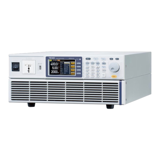
Summary of Contents for TEXIO ASR Series
- Page 1 PROGRAMMING MANUAL AC/DC POWER SOURCE ASR SERIES ASR202-401G ASR302-401G ASR402-401G B71-0507-01...
- Page 2 ■ About a trademark, a registered trademark A company name and the brand name mentioned in this instruction manual are the trademark or the registered trademark of each company or group in each country and region. ■ About this instruction manual When copying the part or all of contents of this instruction manual, seek the copyright holder.
-
Page 3: Table Of Contents
CONTENTS REMOTE CONTROL ......1 1-1. Interface Configuration ......1 1-1-1. Configure Ethernet Connection ............1 1-1-2. Web Server Remote Control Function Check ........3 1-1-3. Socket Server Function Check ............. 4 1-2. USB Interface ........8 1-2-1. USB Remote Interface ................. 8 1-2-2. - Page 4 3-3-7. :MEASure[:SCALar]:CURRent:AVERage ..........33 3-3-8. :MEASure[:SCALar]:CURRent:HARMonic[:RMS] ......... 33 3-3-9. :MEASure[:SCALar]:CURRent:HARMonic:RATio ......... 34 3-3-10. :MEASure[:SCALar]:FREQuency ............34 3-3-11. :MEASure[:SCALar]:POWer[:AC]:APParent ........34 3-3-12. :MEASure[:SCALar]:POWer[:AC]:PFACtor ........34 3-3-13. :MEASure[:SCALar]:POWer[:AC]:REACtive ........35 3-3-14. :MEASure[:SCALar]:POWer[:AC][:REAL] ........... 35 3-3-15. :MEASure[:SCALar]:VOLTage[:RMS] ..........35 3-3-16. :MEASure[:SCALar]:VOLTage:AVERage ........... 35 3-3-17.
- Page 5 3-7-7. :SYSTem:ARBitrary:EDIT:STORe ............50 3-7-8. :SYSTem:ARBitrary:EDIT:TRIangle ............. 51 3-7-9. :SYSTem:BEEPer:STATe ..............51 3-7-10. :SYSTem:COMMunicate:GPIB[:SELF]:ADDRess ....... 52 3-7-11. :SYSTem:COMMunicate:LAN:DHCP ..........52 3-7-12. :SYSTem:COMMunicate:LAN:DNS ............ 53 3-7-13. :SYSTem:COMMunicate:LAN:GATEway ..........53 3-7-14. :SYSTem:COMMunicate:LAN:IPADdress ........... 53 3-7-15. :SYSTem:COMMunicate:LAN:MAC ............ 54 3-7-16. :SYSTem:COMMunicate:LAN:SMASk ..........54 3-7-17.
- Page 6 3-9-1. [:SOURce]:SEQuence:CPARameter ............ 74 3-9-2. [:SOURce]:SEQuence:CSTep .............. 75 3-9-3. [:SOURce]:SEQuence:SPARameter ............ 75 3-9-4. [:SOURce]:SEQuence:STEP ............... 76 3-9-5. [:SOURce]:SEQuence:CONDition ............76 3-9-6. :TRIGger:SEQuence:SELected:EXECute ..........77 3-10. Simulate Commands(Only Simulation Mode Active) ............77 3-10-1. [:SOURce]:SIMulation:CONDition ............77 3-10-2. [:SOURce]:SIMulation:ABNormal:CODE ..........78 3-10-3.
- Page 7 4-5. Warning Status Register Group ... 100 4-6. System Lock Status Register Group ..103 4-7. Standard Event Status Register Group 105 4-8. Status Byte Register & Service Request Enable Register ..........107 Error List ........109 5-1. Command Errors ........ 109 5-2.
-
Page 9: Remote Control
1. REMOTE CONTROL This chapter describes basic configuration of IEEE488.2 based remote control. 1-1. Interface Configuration 1-1-1. Configure Ethernet Connection The Ethernet interface can be configured for a number of different applications. Ethernet can be configured for basic remote control or monitoring using a web server or it can be configured as a socket server. - Page 10 5. To automatically have the network assign an IP address, set DHCP to ON. Otherwise set DHCP to OFF to manually set the Ethernet settings. DHCP ON, OFF 6. If DHCP was set to OFF, configure the remaining LAN parameters. IP Address Subnet Mask Gateway...
-
Page 11: Web Server Remote Control Function Check
1-1-2. Web Server Remote Control Function Check Functionality Enter the IP address of the power supply (for example: http:// XXX.XXX.XXX.XXX) in a web Check browser after the instrument has been configured for LAN (page 1). The web interface allows you to: ... -
Page 12: Socket Server Function Check
1-1-3. Socket Server Function Check To test the socket server functionality, National Background Instruments Measurement and Automation Explorer can be used. This program is available on the NI website, www.ni.com., via a search for the VISA Run-time Engine page, or “downloads”... - Page 13 4. Select Manual Entry of Raw Socket from the popup window. 5. Enter the IP address and the port number of the ASR. The port number is fixed at 2268. 6. Double click the Validate button and press Next.
- Page 14 7. Next configure the Alias (name) of the ASR connection. In this example the Alias is: ASR 8. Click finish. 9. The IP address of the power supply will now appear under Network Devices in the configuration panel. Select this icon now. 10.
- Page 15 12. Click the Input/Output icon. Under the Basic I/O tab, make sure *IDN?\n is entered in the Select or Enter Command drop box. 13. Click Query. The ASR will return the machine identification string into the buffer area: TEXIO TECHNOLOGY, ASRXXX-XXXG, XXXXXXXXX, XX.XX...
-
Page 16: Usb Interface
TEXIO TECHNOLOGY,ASR402-401G,XXXXXXXXX,XX.XX 1-2. USB Interface 1-2-1. USB Remote Interface Type A, host PC side Configuration connector Rear panel Type B, slave ASR side connector 1.1/2.0 (full speed) Speed CDC (communications device USB Class class) 1. Connect the Type A-Type B USB... - Page 17 USB Device Configuration 5. Press Exit[F4] to exit from the rear Exit panel USB settings.
-
Page 18: Usb Remote Control Function Check
USB remote control (page 8). *IDN? This should return the Manufacturer, Model number, Serial number, and Software version in the following format. TEXIO TECHNOLOGY, ASRXXX-XXX, XXXXXXXXX, XX.XX Manufacturer: TEXIO TECHNOLOGY Model number : ASRXXX-XXX Serial number : XXXXXXXXX Software version : XX.XX... -
Page 19: Rs-232C Interface
1-3. RS-232C Interface 1-3-1. RS-232C Remote Interface RS-232C BD-9, male Connector Configuration Baud rate, data bits, parity, stop Parameters bits. 1 2 3 4 5 Pin Assignment 2: RxD (Receive data) 3: TxD (Transmit data) 5: GND 4, 6 ~ 9: No connection 6 789 Use a Null Modem connection (RS-232C cable) Pin Connection... - Page 20 Data bits 7 bits, 8 bits(default) Parity None(default), Odd, Even Stop bits 1 bit(default), 2 bits RS232C Configuration 5. Press Exit[F4] to exit from the Exit RS232C settings. The standard accessory does Not include RS232 Note data cable. Please purchase the additional GTL- 232 which will meet your need for RS232 connection.
-
Page 21: Rs-232C Remote Control Function Check
RS-232C remote control (page 11). *IDN? This should return the Manufacturer, Model number, Serial number, and Software version in the following format. TEXIO TECHNOLOGY, ASRXXX-XXX, XXXXXXXXX, XX.XX Manufacturer: TEXIO TECHNOLOGY Model number : ASRXXX-XXX Serial number : XXXXXXXXX Software version : XX.XX... -
Page 22: Using Realterm To Establish A Remote Connection
1-3-3. Using Realterm to Establish a Remote Connection Realterm is a terminal program that can be Background used to communicate with a device attached to the serial port of a PC or via an emulated serial port via USB. The following instructions apply to version 2.0.0.70. - Page 23 connected device and selecting the Properties option. 5. Start Realterm on the PC as an administrator. Click: Start menu>All Programs>RealTerm>realterm Tip: to run as an administrator, you can right click the Realterm icon in the Windows Start menu and select the Run as Administrator option.
- Page 24 For USB, the baud rate should be fixed to Note 115,200. 7. Click on the Send tab. In the EOL configuration, check on the +LF check boxes. Enter the query: *idn? Click on Send ASCII. TEXIO TECHNOLOGY,ASR402-401,TT1234567,V1.00...
-
Page 25: Gp-Ib Interface
8. The terminal display will return the following: TEXIO TECHNOLOGY, ASRXXX-XXX, XXXXXXXXX, XX.XX (manufacturer, model, serial number, software version) 9. If Realterm fails to connect to the ASR, please check all the cables and settings and try again. 1-4. GP-IB Interface 1-4-1. -
Page 26: Gpib Function Check
5. Press Exit[F4] to exit from the Exit GPIB settings. Maximum 15 devices altogether, 20m cable length, 2m between each device GPIB Constraints Unique address assigned to each device At least 2/3 of the devices turned On ... - Page 27 Start>All Programs>NI MAX 2. From the Configuration panel access; My System>Devices and Interfaces>GPIB0 3. Press the Scan for Instruments button. 4. In the Connected Instruments panel the ASR should be detected as Instrument 0 with the address the same as that configured on the ASR.
- Page 28 Send String text box. 8. Click on the Query button to send the *IDN? query to the instrument. 9. The instrument identification string will be returned to the buffer area: TEXIO TECHNOLOGY, ASRXXX-XXX, XXXXXXXXX, XX.XX (manufacturer, model, serial number, software version) TEXIO TECHNOLOGY,ASR402-401,,V1.00 TEXIO TECHNOLOGY,ASR402-401,TT1234567,V1.00...
-
Page 29: Command Syntax
2. Command Syntax Partial compatibility IEEE488.2 Compatible Partial compatibility Standard SCPI, 1999 Command SCPI commands follow a tree-like structure, organized into nodes. Each level of the Structure command tree is a node. Each keyword in a SCPI command represents each node in the command tree. - Page 30 Example meas:curr? Compound Two or more commands on the same command line. Compound commands are separated with either a semi- colon (;) or a semi-colon and a colon (;:). A semi-colon is used to join two related commands, with the caveat that the last command must begin at the last node of the first command.
- Page 31 Command Commands and queries have two different forms, long and short. The command syntax is Forms written with the short form of the command in capitals and the remainder (long form) in lower case. The commands can be written in capitals or lower-case, just so long as the short or long forms are complete.
- Page 32 Parameters Type Description Example <Boolean> Boolean logic 0, 1 <NR1> integers 0, 1, 2, 3 <NR2> decimal 0.1, 3.14, 8.5 numbers <NR3> floating point 4.5e-1, 8.25e+1 <NRf> any of NR1, 2, 3 1, 1.5, 4.5e-1 <block data> Definitive length arbitrary block data.
-
Page 33: Command List
3. Command List 3-1. Common Commands 3-1-1. *CLS Description The *CLS command clears all the event registers, including the status byte, event status and error queue. Syntax *CLS 3-1-2. *ESE Query Description Sets or queries the Standard Event Status Enable register. -
Page 34: Opc
*IDN? Return <string> Returns the instrument identification as a parameter string in the following format: TEXIO TECHNOLOGY,ASRXXX- XXX,XXXXXXXXX,XX.XX Manufacturer: TEXIO TECHNOLOGY Model number : ASRXXX-XXX Serial number : XXXXXXXXX Firmware version : XX.XX Query 3-1-5. *OPC Description The *OPC? Query returns 1 when all the outstanding commands have completed. -
Page 35: Sav
3-1-8. *SAV Description Saves the settings into memory slot M0 ~ M9. These memory slots are mapped to the preset settings. Syntax *SAV {<NR1>|MINimum|MAXimum} Return <NR1> 0 ~ 9 (as memory M0 ~ M9) parameter Saves to the M0 memory slot. Saves to the M9 memory slot. -
Page 36: Wai
Query Syntax *STB? Return <NR1> Returns the bit sum of the Status Byte parameter register with the MSS bit (bit 6). 3-1-11. *WAI Description Prevents any other commands or queries from being executed until all outstanding commands have completed. Syntax *WAI 3-2. -
Page 37: Data|Trace:sequence:store
Example :DATA:SEQ:REC 1 Loads the data from Seq1. 3-2-3. :DATA|TRACe:SEQuence:STORe Description Saves the sequence data. This command is the equivalent to saving a sequence memory in Sequence mode. Syntax :DATA|TRACe:SEQuence:STORe {<NR1>|MINimum|MAXimum} Parameter <NR1> 0~9 (Seq0 ~ Seq9). Example :DATA:SEQ:STOR 1 Saves the data from Seq1. -
Page 38: Data|Trace:simulation:store
Parameter <NR1> 0~9 (SIM0 ~ SIM9). Example :DATA:SIM:REC 1 Loads the data from SIM1. 3-2-6. :DATA|TRACe:SIMulation:STORe Description Saves the simulation data. This command is the equivalent saving a simulation memory in Simulation mode (SIM0 ~ SIM9). Syntax :DATA|TRACe:SIMulation:STORe {<NR1>|MINimum|MAXimum} Parameter <NR1>... - Page 39 <NR1> 1 – 16 (ARB 1 – 16) Parameter Binary Data includes the #48192<DAB>...<DAB> Indicates the block data is sent. Indicates the number of subsequent numbers. 8192 Indicates the number of subsequent byte data. <DAB>. Indicates 16-bit with 4096 words ..<DAB waveform data.
-
Page 40: Measure Commands
3-3. Measure Commands 3-3-1. :MEASure[:SCALar]:CURRent:CFACt Query Description Returns the output current crest factor (CF). Query syntax :MEASure[:SCALar]:CURRent:CFACtor? Return <NR2> Returns the crest factor. parameter Query 3-3-2. :MEASure[:SCALar]:CURRent:HIGH Description Returns the output current maximum peak value (Imax). Note: Current maximum peak value is defined as the highest peak value in the complete period. -
Page 41: Measure[:Scalar]:Current:peak:hold
3-3-5. :MEASure[:SCALar]:CURRent:PEAK: HOLD Query Description Returns the current peak hold value in amps (IPK Hold). Query syntax :MEASure[:SCALar]:CURRent:PEAK:HOLD? Return <NR2> Returns the peak hold value in amps. Query 3-3-6. :MEASure[:SCALar]:CURRent[:RMS] Description Returns the output current (Irms). Query syntax :MEASure[:SCALar]:CURRent[:RMS]? Return <NR2>... -
Page 42: Measure[:Scalar]:Current:harmonic:ratio
3-3-9. :MEASure[:SCALar]:CURRent:HARMonic :RATio Query Description Returns 41 values covering Total and order 1 to 40 current (Ratio) in harmonic. (Only AC-INT and 50 /60 Hz Active) Query syntax :MEASure[:SCALar]:CURRent:HARMonic:RATio? Return <NR2>,<NR2 Returns the entire 41 values >,<NR2>, containing Total and order 1 to 40 <NR2>…, current (Ratio) in harmonic. -
Page 43: Measure[:Scalar]:Power[:Ac]:Reactive
3-3-13. :MEASure[:SCALar]:POWer[:AC]:RE ACtive Query Description Returns the reactive power (Q). Query syntax :MEASure[:SCALar]:POWer[:AC]:REACtive? Return <NR2> Returns the reactive power in VAR. 3-3-14. :MEASure[:SCALar]:POWer[:AC][:R EAL] Query Description Returns the active power in Watts (P). Query syntax :MEASure[:SCALar]:POWer[:AC][:REAL]? Return <NR2> Returns the power in Watts. 3-3-15. -
Page 44: Measure[:Scalar]:Voltage:low
Note: Voltage maximum peak value is defined as the highest peak value in the complete period. Query syntax :MEASure[:SCALar]:VOLTage:HIGH? Return <NR2> Returns the Vmax value in volts. parameter 3-3-18. :MEASure[:SCALar]:VOLTage:LOW Query Description Returns the output current minimum value (Vmin). Note: Voltage minimum value is defined as the lowest value in the complete period. -
Page 45: Measure:configure:sensing
3-3-21. :MEASure:CONFigure:SENSing Query Description Sets or queries the remote sense configuration. (Only AC-INT, DC-INT, AC-SYNC Mode and 100V, 200V Range and SIN Wave Shape and Time Slew Rate Mode Active) Syntax :MEASure:CONFigure:SENSing {<bool>|OFF|ON} Query Syntax :MEASure:CONFigure:SENSing? Parameter OFF | 0 Turns the remote sense off. ON | 1 Turns the remote sense on. -
Page 46: Memory:sav
3-4-2. :MEMory:SAV Description Saves the settings into memory slot M0 ~ M9. These memory slots are mapped to the preset settings. Equivalent to the *SAV command. Syntax :MEMory:SAV {<NR1>|MINimum|MAXimum} Parameter <NR1> MINimum MAXimum 9 Example :MEMory:SAV 1 Save the settings to M1. 3-5. -
Page 47: Output:protection:clear
Parameter <NR1> 0 ~ 3 OFF| 0 Disabled ON | 1 Enabled SEQ | 2 Sequence function SIM | 3 Simulate function Return <NR1> Returns the selected output state at parameter power-on from 0 to 3. Example :OUTPut:PON 2 Sets sequence function on at power-on. 3-5-3. -
Page 48: Status:operation:enable
Return <NR1> Returns the bit sum of the Operation Condition register. (0~32767) 3-6-2. :STATus:OPERation:ENABle Query Description Sets or queries the bit sum of the Operation Status Enable register. Syntax :STATus:OPERation:ENABle <NR1> Query Syntax :STATus:OPERation:ENABle? Parameter <NR1> 0~32767 Return <NR1> 0~32767 parameter 3-6-3. -
Page 49: Status:questionable[:Event]
Description Sets or queries the bit sum of the positive transition filter of the Operation Status register. Syntax :STATus:OPERation:PTRansition <NR1> :STATus:OPERation:PTRansition? Parameter <NR1> 0~32767 Return <NR1> 0~32767 parameter Query 3-6-6. :STATus:QUEStionable[:EVENt] Description Queries the bit sum of the Questionable Status Event register. -
Page 50: Status:questionable:ntransition
3-6-9. :STATus:QUEStionable:NTRansition Query Description Sets or queries the bit sum of the negative transition filter of the Questionable Status register. Syntax :STATus:QUEStionable:NTRansition <NR1> Query Syntax :STATus:QUEStionable:NTRansition? Parameter <NR1> 0~32767 Return <NR1> 0~32767 parameter 3-6-10. :STATus:QUEStionable:PTRansition Query Description Sets or queries the bit sum of the positive transition filter of the Questionable Status register. -
Page 51: Status:warning:condition
Operation Status Negative Transition 0x0000 WARNing Status Enable 0x0000 WARNing Status Positive Transition 0x7FFF WARNing Status Negative Transition 0x0000 System Lock Status Enable 0x0000 System Lock Status Positive Transition 0x7FFF System Lock Status Negative Transition 0x0000 Summary: The Questionable Status Enable registers, the Operation Status Enable registers, Warning Status registers and System Lock Status registers are both reset to 0. -
Page 52: Status:warning[:Event]
Return <NR1> 0~32767 parameter 3-6-14. :STATus:WARNing[:EVENt] Query Description Queries the Warning Status Event register and clears the contents of the register. Syntax :STATus:WARNing[:EVENt]? Return <NR1> Returns the bit sum of the Warning Status Event register. 3-6-15. :STATus:WARNing:NTRansition Query Description Sets or queries the bit sum of the negative transition filter of the Warning Status register. -
Page 53: Status:lock:enable
Description Queries the System Lock Status register. This query will not clear the register. Syntax :STATus:LOCK:CONDition? Return <NR1> Returns the bit sum of the System Lock Status register. (0~32767) 3-6-18. :STATus:LOCK:ENABle Query Description Sets or queries the bit sum of the System Lock Status Enable register. -
Page 54: Status:lock:ptransition
3-6-21. :STATus:LOCK:PTRansition Query Sets or queries the bit sum of the positive Description transition filter of the System Lock Status register. Syntax :STATus:LOCK:PTRansition <NR1> :STATus:LOCK:PTRansition? Parameter <NR1> 0~32767 Return <NR1> 0~32767 parameter 3-7. System Function Commands 3-7-1. :SYSTem:ARBitrary:EDIT:BUILtin Query Description Sets or queries the built in function of arbitrary edit Syntax :SYSTem:ARBitrary:EDIT:BUILtin TRIangle | STAir... -
Page 55: System:arbitrary:edit:surge
3-7-2. :SYSTem:ARBitrary:EDIT:SURGe Query Description Sets or queries the type and ACV and site parameter for built in Surge wave function Syntax :SYSTem:ARBitrary:EDIT:SURGe <NR1> | SQU | SIN, <NR1> | MINimum | MAXimum, <NR1> | Query Syntax MINimum | MAXimum :SYSTem:ARBitrary:EDIT:SURGe? Parameter<Type SQU | 0 Square waveform type... -
Page 56: System:arbitrary:edit:cfactor2
Syntax :SYSTem:ARBitrary:EDIT:STAir <NR1> | MINimum | MAXimu Query Syntax :SYSTem:ARBitrary:EDIT:STAir? [ MINimum | MAXimum ]? Parameter <NR1> stair : 1 ~ 100 MINimum Minimum stair : 1 MAXimum Maximum stair : 100 Return <NR1> Returns the stair parameter for built parameter in stair wave function Example... -
Page 57: System:arbitrary:edit:clip
Description Sets or queries the crest factor parameter for built in CF-1 wave function Syntax :SYSTem:ARBitrary:EDIT:CFACtor1 <NR2> | MINimum | MAXimum Query Syntax :SYSTem:ARBitrary:EDIT:CFACtor1? [ MINimum | MAXimum ]? Parameter <NR2> crest factor : 1.1 ~ 10.0 MINimum Minimum crest factor : 1.1 MAXimum Maximum crest factor : 10.0 Return... -
Page 58: System:arbitrary:edit:store
3-7-7. :SYSTem:ARBitrary:EDIT:STORe Query Description Saves the waveform data of built in into ARB1 ~ ARB16 Syntax :SYSTem:ARBitrary:EDIT:STORe <NR1> | ARB1 | ARB2 | ARB3 | ARB4 | ARB5 | ARB6 | ARB7 | ARB8 | ARB9 | ARB10 | ARB11 | ARB12 | ARB13 | ARB14 | ARB15 | ARB16 Parameter ARB1 | 0 Saves the waveform data of built in into... -
Page 59: System:arbitrary:edit:triangle
ARB14 | Saves the waveform data of built in into ARB14 ARB15 | Saves the waveform data of built in into ARB15 ARB16 | Saves the waveform data of built in into ARB16 Example :SYST:ARB:EDIT:STOR ARB1 Saves the waveform data of built in into ARB1 3-7-8. -
Page 60: System:communicate:gpib[:Self]:Address
Return <bool> Returns the buzzer status. parameter 3-7-10. :SYSTem:COMMunicate:GPIB[:SEL Query F]:ADDRess Description Sets or queries the GPIB address. Note: The setting will only be valid after the power has been cycled. Syntax :SYSTem:COMMunicate:GPIB[:SELF]:ADDRess <NR1> Query Syntax :SYSTem:COMMunicate:GPIB[:SELF]:ADDRess? Parameter/Retur <NR1> 0~30 Example SYST:COMM:GPIB:ADDR 15 Sets the GPIB address to 15. -
Page 61: System:communicate:lan:dns
3-7-12. :SYSTem:COMMunicate:LAN:DNS Query Description Sets or queries the DNS address. Note: The setting will only be valid after the power has been cycled. Syntax :SYSTem:COMMunicate:LAN:DNS <string> Query Syntax :SYSTem:COMMunicate:LAN:DNS? <string> DNS in string format ( “mask”) Parameter/Retur Applicable ASCII characters: 20H to 7EH SYST:COMM:LAN:DNS “172.16.1.252”... -
Page 62: System:communicate:lan:mac
Parameter/Retur <string> LAN IP address in string format ( “address”) Applicable ASCII characters: 20H to 7EH SYST:COMM:LAN:IPAD “172.16.5.111” Example Sets the IP address to 172.16.5.111. 3-7-15. :SYSTem:COMMunicate:LAN:MAC Query Description Returns the unit MAC address as a string. The MAC address cannot be changed. Query Syntax :SYSTem:COMMunicate:LAN:MAC? Return... -
Page 63: System:communicate:serial[:Receive]:Transmit:baud
Parameter/Retur LOCal All keys are valid. This instrument is n parameter controlled by the front panel controls. REMote All keys are invalid, except for the [local] key and the ability to turn the output off. RWLock All keys are invalid. The instrument can only be controlled remotely. -
Page 64: System:communicate:serial[:Receive]:Transmit:parity
Syntax :SYSTem:COMMunicate:SERial[:RECeive]:TRANs :BITS <NR1> Query Syntax :SYSTem:COMMunicate:SERial[:RECeive]:TRANs :BITS? Parameter 7 bits 8 bits Return 7 bits parameter 8 bits Example SYST:COMM:SER:TRAN:BITS? >+1 Indicates that 8 data bits are used for the UART connection. 3-7-20. :SYSTem:COMMunicate:SERial[:RE Query Ceive]:TRANsmit:PARity Description Sets or queries the parity of the UART connection. Note: The setting will only be valid after the power has been cycled. -
Page 65: System:communicate:serial[:Receive]:Transmit:sbits
3-7-21. :SYSTem:COMMunicate:SERial[:RE Query Ceive]:TRANsmit:SBITs Description Sets or queries the number of stop bits used for the UART connection. Note: The setting will only be valid after the power has been cycled. Syntax :SYSTem:COMMunicate:SERial[:RECeive]:TRANs :SBITs <NR1> Query Syntax :SYSTem:COMMunicate:SERial[:RECeive]:TRANs :SBITs? Parameter 1 stop bit 2 stop bits Return... -
Page 66: System:communicate:usb:rear:state
Query Syntax :SYSTem:COMMunicate:USB:FRONt:STATe? Return <NR1>Absent parameter <NR1>Mass Storage 3-7-24. :SYSTem:COMMunicate:USB:REAR Query :STATe Description Queries the rear panel USB-B port state. Query Syntax :SYSTem:COMMunicate:USB:REAR:STATe? Return <NR1>Absent parameter <NR1>Connected to the PC 3-7-25. :SYSTem:CONFigure[:MODE] Query Description Sets or queries the test mode for the power supply. Syntax :SYSTem:CONFigure[:MODE] {<NR1>|CONTinuous|SEQuence|SIMulation}... -
Page 67: System:configure:extio[:State]
3-7-26. :SYSTem:CONFigure:EXTio[:STATe Query Description Sets or queries the external control state on/off. Syntax :SYSTem:CONFigure:EXTio[:STATe] {<bool>|OFF|ON} Query Syntax :SYSTem:CONFigure:EXTio[:STATe]? Parameter OFF | 0 Turns the external control off. ON | 1 Turns the external control on. Return <bool> Returns the external control status. parameter 3-7-27. -
Page 68: System:ipkhold:time
ON | 1 Turns the freeze hold on. Return <bool> Returns the freeze hold status. parameter 3-7-30. :SYSTem:IPKHold:TIME Query Description Sets or queries the Ipeak hold time for peak current measurement when output on. Syntax :SYSTem:IPKhold:TIME {<NR1>} Query Syntax :SYSTem:IPKhold:TIME? Parameter <NR1>... -
Page 69: System:slew:mode
3-7-33. :SYSTem:SLEW:MODE Query Description Sets or queries slew mode setting. Syntax :SYSTem:SLEW:MODE {<bool>|TIME|SLOPe} Query Syntax :SYSTem:SLEW:MODE? Parameter TIME | 0 Sets the Time mode. SLOPe | 1 Sets the Slope mode. Return <bool> Returns the slew mode setting. parameter Example :SYST:SLEW:MODE TIME Sets the Time mode for slew mode. -
Page 70: Source]:Current:limit:peak:low
Syntax [:SOURce]:CURRent:LIMit:PEAK:LOW {<NR2>|MINimum|MAXimum} Query Syntax [:SOURce]:CURRent:LIMit:PEAK:LOW? [MINimum|MAXimum] Parameter <NR2> Ipk-Low Limit in Arms. MINimum Minimum settable peak current low TEXIO,ASR501-351,,V1.00.19.0000-0 limit MAXimum Maximum settable peak current low limit Return <NR2> Returns the Ipk-Low Limit value parameter Example :CURR:LIM:PEAK:LOW? 14.80 Returns the peak current low limit as 14.8Arms. -
Page 71: Source]:Current:limit:peak:mode
Description Sets or queries the Irms parameter for the continuous operation mode. Syntax [:SOURce]:CURRent:LIMit:RMS[:AMPLitude] {<NR2>|MINimum|MAXimum} Query Syntax [:SOURce]:CURRent:LIMit:RMS[:AMPLitude]? [MINimum|MAXimum] Parameter <NR2> Irms in A. MINimum Minimum settable current MAXimum Maximum settable current Return <NR2> Returns the Irms. parameter Example :CURR:LIM:RMS? 5.25 Returns the Irms setting. -
Page 72: Source]:Frequency:limit:high
Return IRMS limit off parameter IRMS limit on Example :CURR:LIM:RMS:MODE ON Sets IRMS limit enabled. 3-8-6. [:SOURce]:FREQuency:LIMit:HIGH Query Description Sets or queries the frequency upper limit range. (Only AC+DC-INT or AC-INT or AC+DC-ADD or AC-ADD Active) Syntax [:SOURce]:FREQuency:LIMit:HIGH {<NR2>|MINimum|MAXimum} Query Syntax [:SOURce]:FREQuency:LIMit:HIGH? [INimum|MAXimum] Parameter... -
Page 73: Source]:Frequency[:Immediate]
Parameter <NR2> Frequency in Hz. MINimum Minimum settable frequency MAXimum Maximum settable frequency Return <NR2> Returns the frequency limit parameter Example FREQ:LIM:LOW? >60.50 Returns the frequency lower limit. 3-8-8. [:SOURce]:FREQuency[:IMMediate] Query Description Sets or queries the frequency for the immediate trigger. -
Page 74: Source]:Function:thd:format
From 0 – 18, which represent different Parameter / <NR1> Return waveforms, respectively. parameter ARB1 Arbitrary wave 1 ARB2 Arbitrary wave 2 ARB3 Arbitrary wave 3 ARB4 Arbitrary wave 4 ARB5 Arbitrary wave 5 ARB6 Arbitrary wave 6 ARB7 Arbitrary wave 7 ARB8 Arbitrary wave 8 ARB9... -
Page 75: Source]:Mode
Example :SOUR:FUNC:THD:FORM? Returns the THD format as IEC. 3-8-11. [:SOURce]:MODE Query Description Sets or queries the output mode of power supply. Syntax [:SOURce]:MODE {<NR1>|ACDC-INT|AC-INT|DC-INT|ACDC- EXT|AC-EXT|ACDC-ADD|AC-ADD|ACDC- SYNC|AC-SYNC} Query Syntax [:SOURce]:MODE? From 0 – 8, which represent Parameter / <NR1> Return different output modes, parameter respectively. -
Page 76: Source]:Phase:stop:state
Return FREE Start phase Free parameter FIXED Start phase Fixed Example :PHAS:STAR:STAT? FREE Returns the state of start phase as Free. 3-8-13. [:SOURce]:PHASe:STOP:STATe Query Description Sets or queries state of stop phase. (Not available for DC-INT, AC+DC-EXT and AC-EXT) Syntax [:SOURce]:PHASe:STOP:STATe {<bool>|FREE|FIXED} Query Syntax... -
Page 77: Source]:Phase:stop[:Immediate]
3-8-15. [:SOURce]:PHASe:STOP[:IMMediat Query Description Sets or queries the off phase of the waveform. (Not available for DC-INT, AC+DC-EXT and AC-EXT) Note: Sets the off phase of the waveform after the output has been turned off. Syntax [:SOURce]:PHASe:STOP[:IMMediate] {<NR2>|MINimum|MAXimum} Query Syntax [:SOURce]:PHASe:STOP[:IMMediate]? [MINimum|MAXimum] Parameter/Retur... -
Page 78: Source]:Voltage:range
3-8-17. [:SOURce]:VOLTage:RANGe Query Description Sets or queries the voltage range. Syntax [:SOURce]:VOLTage:RANGe {<NR1>|100|200|AUTO} Query Syntax [:SOURce]:VOLTage:RANGe? From 0 – 2, which represent Parameter / <NR1> Return different voltage ranges, parameter respectively. 100V 200V AUTO AUTO (Only AC+DC-INT or AC-INT or DC-INT or AC+DC-sync or AC- sync Active) Example :SOUR:VOLT:RANG? -
Page 79: Source]:Voltage:limit:high
3-8-19. [:SOURce]:VOLTage:LIMit:HIGH Query Description Sets or queries the voltage high limit. (Only AC+DC-INT or DC-INT or AC+DC-ADD or AC+DC- Sync Active) Syntax [:SOURce]:VOLTage:LIMit:HIGH {<NR2>|MINimum|MAXimum} Query Syntax [:SOURce]:VOLTage:LIMit:HIGH? [MINimum|MAXimum] Parameter <NR2> Voltage high limit MINimum Minimum voltage high limit MAXimum Maximum voltage high limit Return <NR2>... -
Page 80: Source]:Voltage:limit:peak
[:SOURce]:VOLTage:LIMit:PEAK 3-8-21. Query Description Sets or Queries the Value of Vpp in Specific Mode(AC-INT or AC-ADD or AC-Sync) and Wave Shape(TRI or ARB) and V Unit(p-p) Syntax [:SOURce]:VOLTage:LIMit:PEAK <NR2> | MINimum | MAXimum Query Syntax [:SOURce]:VOLTage:LIMit:PEAK? [ MINimum | MAXimum ] Parameter/Retur <NR2>... -
Page 81: Source]:Voltage[:Level][:Immediate]:Offset
3-8-23. [:SOURce]:VOLTage[:LEVel][:IMMed Query iate]:OFFSet Description Sets or queries the voltage offset value. (Only AC+DC-INT or DC-INT or AC+DC-ADD or AC+DC- Sync Active) Syntax [:SOURce]:VOLTage[:LEVel][:IMMediate]:OFFSet {<NR2>(V)|MINimum|MAXimum} Query Syntax [:SOURce]:VOLTage[:LEVel][:IMMediate]:OFFSet? [MINimum|MAXimum] Parameter/Retur <NR2> Voltage offset value n parameter MINimum Minimum voltage offset value MAXimum Maximum voltage offset value Example... -
Page 82: Sequence Commands
3-9. Sequence Commands 3-9-1. [:SOURce]:SEQuence:CPARameter Description Sets the common parameters for the Sequence mode. Please see the user manual for a full description of each parameter. Syntax [:SOURce]:SEQuence:CPARameter {<NR2>,<NR2>,<bool>|OFF|ON,<NR2>,<bool>|O FF|ON,<NR1>|CONTinue|END|HOLD,<NR1>,<bo ol>|OFF|ON,<NR1>,<bool>|OFF|ON,<NR1>,<bool >|OFF|ON,<NR1>,<bool>|OFF|ON,<bool>|OFF|O Query Syntax [:SOURce]:SEQuence:CPARameter? Parameter <NR2> Step Time <NR2> On phase <bool>|OFF|ON|F On phase off (free)(1) / on... -
Page 83: Source]:Sequence:cstep
Return <NR2>,<NR2>,<bool>,<NR2>,<bool>,<NR1>,<NR parameter 1>, <bool>,<NR1>,<NR1>,<bool>,<NR1>,<bool>, <bool> Returns the common parameters in the following order: Step time, on phase, on phase on/off, off phase, off phase on/off, term settings, jump step number, jump on/off, jump count, code on/off, branch1, branch1 on/off, branch2, branch2 on/off, trig out on/off. -
Page 84: Source]:Sequence:step
<NR2> Frequency <NR1>|CONSt| Frequency mode: Constant(1) | KEEP|SWEep Keep(2) | Sweep(3) Waveform ARB1|ARB2|ARB3|ARB4|ARB5 |ARB6|ARB7|ARB8|ARB9|ARB 10|ARB11|ARB12|ARB13|ARB1 4|ARB15|ARB16|SIN|SQU|TRI <NR1> Phase angle. Fixed to 0. Return <NR2>,<NR1>|CONSt|KEEP|SWEep,<NR2>,<NR parameter 1>|CONSt|KEEP|SWEep,<NR2>,<NR1>|CONSt|K EEP|SWEep,ARB1|ARB2|ARB3|ARB4|ARB5|ARB 6|ARB7|ARB8|ARB9|ARB10|ARB11|ARB12|ARB1 3|ARB14|ARB15|ARB16|SIN|SQU|TRI,<NR1> Returns the step parameters in the following order: ACV, ACV mode, DCV, DCV mode, frequency, frequency mode, wave, phase. -
Page 85: Trigger:sequence:selected:execute
parameter status 1 (Run mode) 2 (Hold mode) Example :SEQ:COND? 3-9-6. :TRIGger:SEQuence:SELected:EXEC Query Description Sets to execute actions for sequence mode Syntax :TRIGger:SEQuence:SELected:EXECute {STOP|STARt|HOLD|BRAN1|BRAN2} Parameter STOP Stops sequence execution STARt Starts sequence execution HOLD Holds sequence execution BRAN1 Jumps to Branch 1 execution BRAN2 Jumps to Branch 2 execution Example... -
Page 86: Source]:Simulation:abnormal:code
3-10-2. [:SOURce]:SIMulation:ABNormal:CO Query Description Sets the external trigger output for the abnormal step parameter. This option is only applicable when in the Simulation mode. Syntax [:SOURce]:SIMulation:ABNormal:CODE {<NR1>|MINimum|MAXimum} Query Syntax [:SOURce]:SIMulation:ABNormal:CODE? [MINimum|MAXimum] Parameter/Retur <NR1> External trigger output, 0=LL, 1=LH, n parameter 2=HL, 3=HH. -
Page 87: Source]:Simulation:abnormal:phase:start[:Immediate]
Syntax [:SOURce]:SIMulation:ABNormal:PHASe:STARt :ENABle {<bool>|OFF|ON|FREE|FIXED} Query Syntax [:SOURce]:SIMulation:ABNormal:PHASe:STARt :ENABle? Parameter/Retur OFF | 0 | Disabled n parameter FREE ON | 1 | Enabled FIXED Example :SIM:ABN:PHAS:STAR:ENAB 1 Enable the ON Phs. 3-10-5. [:SOURce]:SIMulation:ABNormal:PH Query ASe:STARt[:IMMediate] Description Sets or queries the ON Phs parameter of the abnormal step for the Simulation mode. -
Page 88: Source]:Simulation:abnormal:phase:stop[:Immediate]
Parameter/Retur OFF | 0 | Disabled n parameter FREE ON | 1 | Enabled FIXED Example :SIM:ABN:PHAS:STOP:ENAB 1 Enable the OFF Phs. 3-10-7. [:SOURce]:SIMulation:ABNormal:PH Query ASe:STOP[:IMMediate] Description Sets or queries the OFF Phs parameter of the abnormal step for the Simulation mode. Note: Sets the off phase of the waveform after the output has been turned off. -
Page 89: Source]:Simulation:abnormal:voltage
Example :SIM:ABN:TIME 1 Sets the abnormal step time to 1 second. 3-10-9. [:SOURce]:SIMulation:ABNormal:VO Query LTage Description Sets or queries the Vset parameter of the abnormal step for the Simulation mode. Syntax [:SOURce]:SIMulation:ABNormal:VOLTage {<NR2>|MINimum|MAXimum} Query Syntax [:SOURce]:SIMulation:ABNormal:VOLTage? [MINimum|MAXimum] <NR2> Voltage of the abnormal step. Parameter/Retur MINimum Minimum settable voltage... -
Page 90: Source]:Simulation:initial:frequency
Description Sets the external trigger output for the initial step parameter. This option is only applicable when in the Simulation mode. Syntax [:SOURce]:SIMulation:INITial:CODE {<NR1>|MINimum|MAXimum} Query Syntax [:SOURce]:SIMulation:INITial:CODE? [MINimum|MAXimum] Parameter/Retur <NR1> 0=LL, 1=LH, 2=HL, 3=HH n parameter MINimum 0 (LL) MAXimum 3 (HH) Example SIM:INIT:CODE 1 3-10-12. -
Page 91: Source]:Simulation:initial:phase:start[:Immediate]
Parameter/Retur OFF | 0 | Disabled n parameter FREE ON | 1 | Enabled FIXED Example :SIM:INIT:PHAS:STAR:ENAB 1 Enable the ON Phs. 3-10-14. [:SOURce]:SIMulation:INITial:PHA Query Se:STARt[:IMMediate] Description Sets or queries the ON Phs parameter of the initial step for the Simulation mode. Syntax [:SOURce]:SIMulation:INITial:PHASe:STARt [:IMMediate] {<NR2>|MINimum|MAXimum}... -
Page 92: Source]:Simulation:initial:phase:stop[:Immediate]
3-10-16. [:SOURce]:SIMulation:INITial:PHA Query Se:STOP[:IMMediate] Description Sets or queries the OFF Phs parameter of the initial step for the Simulation mode. Note: Sets the off phase of the waveform after the output has been turned off. Syntax [:SOURce]:SIMulation:INITial:PHASe:STOP [:IMMediate] {<NR2>|MINimum|MAXimum} Query Syntax [:SOURce]:SIMulation:INITial:PHASe:STOP [:IMMediate]? [MINimum|MAXimum] <NR2>... -
Page 93: Source]:Simulation:normal<1|2>:Code
3-10-18. [:SOURce]:SIMulation:NORMal<1|2 Query >:CODE Description Sets the external trigger output for the normal 1 or normal 2 step parameter. This option is only applicable when in the Simulation mode. Syntax [:SOURce]:SIMulation:NORMal<1|2>:CODE {<NR1>|MINimum|MAXimum} Query Syntax [:SOURce]:SIMulation:NORMal<1|2>:CODE? [MINimum|MAXimum] Parameter/Retur <NR1> 0=LL, 1=LH, 2=HL, 3=HH n parameter MINimum 0 (LL) -
Page 94: Source]:Simulation:normal<1|2>:Phase:start[:Immediate]
Description Enables/Disables (Fixed/Free) the ON Phs parameter of the normal1 or normal2 step for the Simulation mode. Syntax [:SOURce]:SIMulation:NORMal<1|2>:PHASe:STA Rt:ENABle { <bool>|OFF|ON|FREE|FIXED} Query Syntax [:SOURce]:SIMulation:NORMal<1|2>:PHASe:STA Rt:ENABle? <1|2> Normal 1 or Normal 2 Parameter/Retur OFF | 0 | Disabled n parameter FREE ON | 1 | Enabled... -
Page 95: Source]:Simulation:normal<1|2>:Phase:stop[:Immediate]
Description Enables/Disables (Fixed/Free) the OFF Phs parameter of the normal1 or normal2 step for the Simulation mode. Syntax [:SOURce]:SIMulation:NORMal<1|2>:PHASe:STO P:ENABle {<bool>|OFF|ON|FREE|FIXED} Query Syntax [:SOURce]:SIMulation:NORMal<1|2>:PHASe:STO P:ENABle? Parameter/Retur <1|2> Normal 1 or Normal 2 n parameter OFF | 0 | Disabled FREE ON | 1 | Enabled FIXED... -
Page 96: Source]:Simulation:normal<1|2>:Time
3-10-24. [:SOURce]:SIMulation:NORMal<1|2 Query >:TIME Description Sets or queries the Time parameter of the normal1 or normal2 step for the Simulation mode. Syntax [:SOURce]:SIMulation:NORMal<1|2>:TIME {<NR2>|MINimum|MAXimum} Query Syntax [:SOURce]:SIMulation:NORMal<1|2>:TIME? [MINimum|MAXimum] <1|2> Normal 1 or Normal 2 Parameter/Retur <NR2> Time of the step in seconds n parameter MINimum MAXimum... -
Page 97: Source]:Simulation:repeat:count
3-10-26. [:SOURce]:SIMulation:REPeat:CO Query Description Sets or queries the repeat count for the Simulation mode. Syntax [:SOURce]:SIMulation:REPeat:COUNt {<NR1>|MINimum|MAXimum} Query Syntax [:SOURce]:SIMulation:REPeat:COUNt? [MINimum|MAXimum] <NR1> 0 ~ 9999 (0 = infinite loop) Parameter/Retur MINimum n parameter MAXimum 9999 Example :SIM:REP:COUN 1 Sets the repeat count to 1. 3-10-27. -
Page 98: Source]:Simulation:transition<1|2>:Code
Query Syntax [:SOURce]:SIMulation:TRANsition<1|2>:TIME? [MINimum|MAXimum] <NR2> Time of the step in seconds Parameter/Retur MINimum n parameter MAXimum 999.9999s Example :SIM:TRAN1:TIME 1 Sets the step time to 1 second. 3-10-29. [:SOURce]:SIMulation:TRANsition< Query 1|2>:CODE Description Sets the external trigger output for the transition step parameter. -
Page 99: Input Subsystem Command
3-11. Input Subsystem Command 3-11-1. :INPut:GAIN Query Description Sets or queries the input gain value. (Only AC+DC- EXT or AC-EXT or AC+DC-ADD or AC-ADD Active) Syntax :INPut:GAIN {<NR2>(V)|MINimum|MAXimum} Query Syntax :INPut:GAIN? [MINimum|MAXimum] Parameter/Retur <NR2> Input gain value n parameter MINimum Minimum input gain value MAXimum Maximum input gain value... -
Page 100: Display Command
3-12. Display Command 3-12-1. :DISPlay[:WINDow]:DESign:MODE Description Sets two display mode. Syntax :DISPlay[:WINDow]:DESign:MODE{NORMal|SIMP Parameter MORMal Configure setup and Measurement. SIMPle All measurement times. Example :DISP:DES:MODE NORM Sets standard normal display. 3-12-2. :DISPlay[:WINDow]:MEASure:SOUR ce<1|2|3> Description Sets standard normal display to measurement items 1 – 3. Syntax :DISPlay[:WINDow]:MEASure:SOURce<1|3>... -
Page 101: Status Register Overview
The status registers are used to determine the status of the power supply. The status registers maintain the status of the protection conditions, operation conditions and instrument errors. The ASR Series have a number of register groups: Questionable Status Register Group ... -
Page 102: The Status Registers
4-2. The Status Registers System Lock Status Register Condition PTR/NTR Event Enable Questionable Status Register Condition PTR/NTR Event Enable Operation Status Register Output Buffer Condition PTR/NTR Event Enable Error Queue Service Status Request Byte Enable Register Register Warning Status Register Condition PTR/NTR Event... -
Page 103: Questionable Status Register Group
4-3. Questionable Status Register Group Overview The Questionable Status Register Group indicates if any protection modes or limits have been tripped. Questionable Status Register Condition PTR/NTP Event Enable & & & & & & & & & & & & &... - Page 104 Output Short Call attention to output terminal short status Over Ipeak+ Current or Over Ipeak- Current Positive/Negative output current peak value is excessive. Fan Failure Fan failure. Contact service center. Calibration Data Error The calibration data is abnormal or out of allowance range.
- Page 105 PTR/NTR Filters The PTR/NTR (Positive/Negative transition) register determines the type of transition conditions that will set the corresponding bit in the Event Registers. Use the Positive transition filter to view events that change from false to positive, and use the negative transition filter to view events that change from positive to negative.
-
Page 106: Operation Status Register Group
4-4. Operation Status Register Group Overview The Operation Status Register Group indicates the operating status of the power supply. Operation Status Register Condition PTR/NTP Event Enable & & & & & & & & & & & & & & &... - Page 107 PTR/NTR Filters The PTR/NTR (Positive/Negative transition) register determines the type of transition conditions that will set the corresponding bit in the Event Registers. Use the Positive transition filter to view events that change from false to positive, and use the negative transition filter to view events that change from positive to negative.
-
Page 108: Warning Status Register Group
4-5. Warning Status Register Group Overview The Warning Status Register Group is a secondary protection status register for the supply output. Warning Status Register Condition PTR/NTP Event Enable & & & & & & & & & & & & &... - Page 109 DCAC Power Unit Error Internal DCAC power unit function error. DCDC Power Unit Error Internal DCDC power unit function error. External Sync Frequency Error The external synchronization signal input frequency is out of the allowance range. (40Hz ~ 999.9Hz) Sensing Voltage Error Remote sense connection wire is abnormal or over maximum compensation voltage.
- Page 110 Condition The System Lock Status Condition Register indicates the system lock status of the power Register supply. If a bit is set in the Condition register, it indicates that the event is true. Reading the condition register does not change the state of the condition register.
-
Page 111: System Lock Status Register Group
4-6. System Lock Status Register Group Overview The System Lock Status Register Group indicates if system lock protection modes have been tripped. System Lock Status Register Condition PTR/NTP Event Enable & & & & & & & & & & &... - Page 112 PFC Power Unit Error Internal PFC power unit function error. Condition The System Lock Status Condition Register Register indicates the system lock status of the power supply. If a bit is set in the Condition register, it indicates that the event is true. Reading the condition register does not change the state of the condition register.
-
Page 113: Standard Event Status Register Group
4-7. Standard Event Status Register Group Overview The Standard Event Status Register Group indicates if any errors have occurred. The bits of the Event register are set by the error event queue. Standard Event Status Register Event Enable & & &... - Page 114 QUE (Query Error) The Query Error bit is set in response to an error reading the Output Queue. This can be caused by trying to read the Output Queue when there is no data present. DDE (Device Dependent Error) Device specific error. EXE (Execution Error) The EXE bit indicates an execution error due to one of...
-
Page 115: Status Byte Register & Service Request Enable Register
4-8. Status Byte Register & Service Request Enable Register Overview The Status Byte register consolidates the status events of all the status registers. The Status Byte register can be read with the *STB? query and can be cleared with the *CLS command. Output Buffer From System... - Page 116 OPER (Operation Status Register) Status Byte Any bits set in the Status byte register acts as a Register summary register for all the three other status registers and indicates if there is a service request, an error in the Error Queue or data in the Output Queue.
-
Page 117: Error List
5. Error List 5-1. Command Errors Overview An <error/event number> in the range [ -199 , - 100 ] indicates that an IEEE 488.2 syntax error has been detected by the instrument’s parser. The occurrence of any error in this class shall cause the command error bit (bit 5) in the event status register (IEEE 488.2, section 11.5.1) to be set. - Page 118 Error Code Description -100 Command This is the generic syntax error for devices that Error cannot detect more specific errors. This code indicates only that a Command Error as defined in IEEE 488.2,11.5.1.1.4 has occurred. -102 Syntax An unrecognized command or data type was encountered;...
- Page 119 -113 Undefined The header is syntactically correct, but it is header undefined for this specific device; for example, *XYZ is not defined for any device. -114 Header The value of a numeric suffix attached to a suffix out of program mnemonic, see Syntax and Style range section 6.2.5.2, makes the header invalid.
- Page 120 -158 String data A string data element was encountered but was not allowed not allowed by the device at this point in parsing. -160 Block data This error, as well as errors -161 through -169, error are generated when parsing a block data element.
-
Page 121: Execution Errors
5-2. Execution Errors An <error/event number> in the range [ -299 , - Overview 200 ] indicates that an error has been detected by the instrument’s execution control block. The occurrence of any error in this class shall cause the execution error bit (bit 4) in the event status register (IEEE 488.2, section 11.5.1) to be set. - Page 122 -203 Command Indicates that a legal password-protected protected program command or query could not be executed because the command was disabled. -211 Trigger Indicates that a GET, *TRG, or triggering signal ignored was received and recognized by the device but was ignored because of device timing considerations;...
-
Page 123: Device Specific Errors
5-3. Device Specific Errors Overview An <error/event number> in the range [ -399 , - 300 ] or [ 1 , 32767 ] indicates that the instrument has detected an error which is not a command error, a query error, or an execution error;... -
Page 124: Query Errors
5-4. Query Errors Overview An <error/event number> in the range [ -499 , - 400 ] indicates that the output queue control of the instrument has detected a problem with the message exchange protocol described in IEEE 488.2, chapter 6. The occurrence of any error in this class shall cause the query error bit (bit 2) in the event status register (IEEE 488.2, section 11.5.1) to be set. -
Page 125: Appendix
6. APPENDIX 6-1. Factory Default Settings The following default settings are the factory configuration settings for the ASR series. For details on how to return to the factory default settings, please see the user manual. AC+DC-INT Mode ASR202-401G ASR302-401G ASR402-401G... - Page 126 AC+DC-EXT Mode ASR202-401G ASR302-401G ASR402-401G Range 100V GAIN 100.0 IRMS 21.00 A 31.50 A 42.00 A IPK Limit +/- 126.0 A +/- 189.0 A +/- 252.0 A AC-EXT Mode ASR202-401G ASR302-401G ASR402-401G Range 100V GAIN 100.0 IRMS 21.00 A 31.50 A 42.00 A IPK Limit +/- 126.0 A...
- Page 127 AC+DC-SYNC Mode ASR202-401G ASR302-401G ASR402-401G Range 100V Wave Shape 0.0 Vrms +0.0 Vdc LINE IRMS 21.00 A 31.50 A 42.00 A V Limit +/- 285.0 Vpp F Limit 999.9 Hz IPK Limit +/- 126.0 A +/- 189.0 A +/- 252.0 A ON Phs OFF Phs AC-SYNC Mode...
- Page 128 RS232C G Type Baudrate 9600 Databits 8bits Parity None Stopbits 1bit GPIB G Type Address Sequence Mode Step Time 0.1000 s 0.0, CT 0.0, CT Fset 50.0, CT Wave Jump To Jump Cnt Branch 1 Branch 2 Term CONTI Sync Code ON Phs Free OFF Phs...
- Page 129 ARB 1~16 ARB1 ARB2 ARB3 ARB4 ARB5 ARB6 ARB7 ARB8 ARB9 ARB10 ARB11 ARB12 ARB13 ARB14 ARB15 ARB16...
- Page 130 7F Towa Fudosan Shin Yokohama Bldg. 2-18-13, Shin Yokohama, Kohoku-ku, Yokohama, Kanagawa, 222-0033 Japan https://www.texio.co.jp...
Need help?
Do you have a question about the ASR Series and is the answer not in the manual?
Questions and answers