Table of Contents

Related Manuals for Varex Imaging 4343W


Summary of Contents for Varex Imaging 4343W
- Page 1 4343W/4336W-G5/2530W-G5 X- ray Detectors Before using the X-ray detectors, be sure to read this manual thoroughly along with any other manuals for the software and other system components. Keep this manual where it is easily accessible. ®...
- Page 2 Before You Begin 4343W/4336W-G5/2530W-G5 X-ray Detectors Before You Begin • To avoid personal injury or product damage, read the manual and all accompanying papers carefully before operating the X-ray detectors. • The X-ray detectors are intended for use by qualified professional personnel who are trained and knowledgeable in the use of X-ray detectors, X-ray systems, and electrical equipment.
- Page 3 4343W/4336W-G5/2530W-G5 X-ray Detectors For Your Safety To avoid personal injury or product damage, read this manual and all accompanying information carefully before handling, installing, or using the X-ray detector. Follow all instructions, warnings, and cautions in this manual and all warnings and cautions printed on the warning label.
- Page 4 Before You Begin 4343W/4336W-G5/2530W-G5 X-ray Detectors Installation and Environment of Use The X-ray detectors are intended to be installed, maintained, and used WARNING by qualified professional personnel who are trained and qualified in the installation, maintenance, and use of X-ray equipment. All parts of the X-ray detectors are suitable for use within the patient environment.
- Page 5 4343W/4336W-G5/2530W-G5 X-ray Detectors It is important that the X-ray detector is not directly connected to the Caution installed network. Connection of the X-ray detector with the installed computer network may disturb the IT environment. Do not operate the X-ray detector in a location with the following...
- Page 6 X-ray detector, when a wireless connection is not available • for service Note Varex Imaging tests every X-ray detector, using the tether cable, for com- munication and link speed defects. Varex’s supplier of the tether cable individually tests each cable before shipping. www.vareximaging.com...
- Page 7 4343W/4336W-G5/2530W-G5 X-ray Detectors Handling Never disassemble, modify, or alter the X-ray detector, its components, WARNING battery pack, battery charger, or accessories. Ignoring this warning may cause electrical shock and/or unknown hazards, which may result in severe personal injury, death, or substantial product damage.
- Page 8 Before You Begin 4343W/4336W-G5/2530W-G5 X-ray Detectors Battery, Inductive Charger, and X-ray Detector Power Supply Do not use the battery pack if the casing is broken or if it emits an WARNING unusual odor, smoke, or excessive heat, or if it leaks any substance.
- Page 9 4343W/4336W-G5/2530W-G5 X-ray Detectors Do not connect the battery pack to an electrical outlet directly, or to WARNING any other electrical source not described in the manual. Do not drop or hit the battery against hard objects since this may cause...
- Page 10 Before You Begin 4343W/4336W-G5/2530W-G5 X-ray Detectors The electromagnetic emission of the X-ray detector may influence Caution implantable medical devices like pacemakers. Check the information for these devices. Use a Wi-Fi friendly environment and avoid Bluetooth devices, Caution mobile phones, and other Wi-Fi devices close to the X-ray detector or router.
- Page 11 4343W/4336W-G5/2530W-G5 X-ray Detectors If a Problem Occurs If any abnormal condition, such as smoke, fumes, or strange sounds, is WARNING evident, remove the battery from the X-ray detector, and immediately ask your establishment’s safety representative to contact your dealer, distributor, or device manufacturer.
- Page 12 Before You Begin 4343W/4336W-G5/2530W-G5 X-ray Detectors This page intentionally left blank. www.vareximaging.com...
-
Page 13: Table Of Contents
Getting Started ......................16 11.1 Shipment Contents ......................16 11.2 Data Interface and Cables ....................16 11.2.1 Connecting the Service Cable for 4343W ............ 17 11.2.2 Connecting the Tether Cable for 4336W-G5 and 2530W-G5....19 11.3 Software Installation ...................... 21 11.3.1 SDK Files ...................... - Page 14 Troubleshooting ............64 15.1 After-sales Service for Varex Imaging Products......68 15.2 Disposing of the X-ray Detector and Battery .
- Page 15 4343W/4336W-G5/2530W-G5 X-ray Detectors Table of Contents 16.0 Safety - Electromagnetic Interference ............... 69 16.1 Electromagnetic Emissions .................... 69 16.2 Electromagnetic Immunity .................... 70 16.3 Radio Frequency (RF) Compliance Information ............76 16.3.1 United States FCC/IC Compliance ............. 76 17.0 Regulatory ........................79 17.1...
- Page 16 Table of Contents 4343W/4336W-G5/2530W-G5 X-ray Detectors This page intentionally left blank. www.vareximaging.com...
- Page 17 Fluctuations & Flicker ..................... 70 Table 19 4343W ESD, Transient/Burst, Surge, Voltage Variation, Magnetic Fields ..... 70 Table 20 4343W Test Specs for Enclosure Port Immunity to RF Wireless Communications Equipment ........................72 Table 21 4336W-G5 and 2530W-G5 ESD, Transient/Burst, Surge, Voltage Variation, Mag- netic Fields........................
- Page 18 List of Tables 4343W/4336W-G5/2530W-G5 X-ray Detectors This page intentionally left blank. xviii www.vareximaging.com...
- Page 19 List of Figures Figure 1 Typical Detector Configuration ..................8 Figure 2 4343W X-ray Detector Surfaces and Features ............. 13 Figure 3 4336W-G5 X-ray Detector Surfaces and Features ............14 Figure 4 2530W-G5 X-ray Detector Surfaces and Features ............15 Figure 5 X-ray Detector as Access Point ..................
- Page 20 Figure 60 4343W Detector and Wireless Label Locations ......77 Figure 61 4336W-G5 Detector and Wireless Label Locations.
- Page 21 4343W/4336W-G5/2530W-G5 X-ray Detectors List of Figures Figure 63 4343W X-ray Detector Dimensions in mm ..............84 Figure 64 4343W X-ray Detector Dimensions in mm ..............84 Figure 65 4336W-G5 X-ray Detector Dimensions in mm............85 Figure 66 4336W-G5 X-ray Detector Dimensions in mm............85 Figure 67 2530W-G5 Detector Dimension in mm ................
- Page 22 List of Figures 4343W/4336W-G5/2530W-G5 X-ray Detectors This page intentionally left blank. xxii www.vareximaging.com...
-
Page 23: Scope
There are no contraindications. Intended Use Varex Imaging Wireless X-ray detectors and their accessories are components designed to be integrated into products by X-ray system manufacturers. Final application and intended use are determined by the X-ray system manufacturer and is based on the completed X-ray system design. -
Page 24: Abbreviations
Cesium Iodide Light Emitting Diode Original Equipment Manufacturer PREP Prepare Request Software Developer Kit ViVA Varex Imaging and Viewing Application Varex Smart Panel vTrigger Automatic Exposure Detection WLAN Wireless Local Area Network References Table 2 includes a list of documents referred to in this manual. For access to the following refer- ences, contact your dedicated Varex representative. -
Page 25: Definition Of Symbols
4343W/4336W-G5/2530W-G5 X-ray Detectors Definition of Symbols Table 3 Definition of Symbols Symbol Description On (power connection) Off (power disconnection) Handle with Care Direct Current Authorized Representative in the European Community/European Union Note: This symbol does not apply to model 2530W-G5 IP68 The X-ray detectors have an IP68 ingress protection rating. - Page 26 4343W/4336W-G5/2530W-G5 X-ray Detectors Table 3 Definition of Symbols (Continued) Symbol Description Type B Applied Part Underwriters Laboratory Safety Mark China RoHS environmentally friendly for 10 years www.vareximaging.com...
-
Page 27: Standards And Regulations
All regulatory certificates are valid only if the original accessories are used. All regulatory certificates are rendered invalid if any modifications to the Product are made, or any portion thereof, without obtaining the prior written authorization of Varex Imaging. Table 4... -
Page 28: Storage And Use Conditions
4343W/4336W-G5/2530W-G5 X-ray Detectors Storage and Use Conditions Environments outside the specification reduce the lifetime and may irreparably damage the X-ray detector. Table 5 Environmental Conditions Category Limits Storage & Transport Temperature (ambient) -20º C to +55º C Operating Temperature (ambient) 10º... -
Page 29: Temperature Sensors
2530W-G5 T1 Maximum 48º C Note The T1 (4343W) and T2 temperature sensors are used to monitor the internal temperature of the glass. These are the only temperature sensors that need to be monitored by the OEM, see Table If the maximum temperature is reached, the X-ray detector must be WARNING turned off and allowed to cool. -
Page 30: Description Of The X-Ray Detectors
A Service Cable is supplied with the 4343W to allow for set-up of the wireless interface and to retrieve images from the X-ray detector in case of failed wireless transmission. -
Page 31: X-Ray Detector Specifications
4343W/4336W-G5/2530W-G5 X-ray Detectors 10.1 X-ray Detector Specifications Table 7 Specifications Sensor 4343W 4336W-G5 2530W-G5 Detector Amorphous Silicon active Amorphous Silicon active Amorphous Silicon active TFT/PIN diode TFT/PIN diode TFT/PIN diode Technology Technology Technology Scintillator CsI Premium, CsI CsI Premium, CsI... - Page 32 4343W/4336W-G5/2530W-G5 X-ray Detectors Table 7 Specifications (Continued) Radio 4343W 4336W-G5 2530W-G5 Antenna 2 x IPEX connector for 2 x IPEX connector for 2 x IPEX connector for 2T2R 2T2R 2T2R Frequencies • • • UNII - 1: 5150MHz - UNII - 1: 5150MHz -...
- Page 33 4343W/4336W-G5/2530W-G5 X-ray Detectors Table 7 Specifications (Continued) Transmit Power • • • 802.11a: 14.5 + 1dBm 802.11a: 14.5 + 1dBm 802.11a: 12 + 1dBm WIFI_Chain 0 • • • 802.11n/ac 802.11n/ac 802.11n/ac 20_5180MHz~5240MH 20_5180MHz~5240MH 20_5180MHz~5240MH z: 9 + 1dBm z: 13.5 + 1dBm z: 13.5 + 1dBm...
- Page 34 4343W/4336W-G5/2530W-G5 X-ray Detectors Table 7 Specifications (Continued) 802.11a: ≤ - 802.11a: ≤ - 802.11a: ≤ - • • • Receive Sensitivity 70dBm@54Mbps 70dBm@54Mbps 70dBm@54Mbps • • • 802.11n/5GHz (HT20): 802.11n/5GHz (HT20): 802.11n/5GHz (HT20): ≤ -60dBm@MCS7 ≤ -60dBm@MCS7 ≤ -60dBm@MCS7 •...
-
Page 35: X-Ray Detector Surfaces And Features
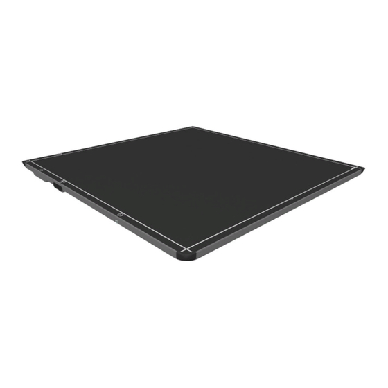
4343W/4336W-G5/2530W-G5 X-ray Detectors 10.2 X-ray Detector Surfaces and Features Figure 2 4343W X-ray Detector Surfaces and Features Table 8 Description of Detector Surfaces and Features Number Description Handles Battery Alignment Marker Battery and Battery Well Replaceable Battery Latch Antennas Inductive Charging Receiver... -
Page 36: Table 9 Description Of Detector Surfaces And Features
4343W/4336W-G5/2530W-G5 X-ray Detectors Figure 3 4336W-G5 X-ray Detector Surfaces and Features Table 9 Description of Detector Surfaces and Features Number Description Handles Battery Alignment Marker Battery and Battery Well Replaceable Battery Latch Inductive Charging Receiver Antennas Patient Contact Surface Tether Cable Connection... -
Page 37: Table 10 Description Of Detector Surfaces And Features
4343W/4336W-G5/2530W-G5 X-ray Detectors Figure 4 2530W-G5 X-ray Detector Surfaces and Features Table 10 Description of Detector Surfaces and Features Number Description Handle Battery Alignment Marker and Contacts Battery Well Replaceable Battery Latch Inductive Charging Receiver Antennas Tether Cable Connection LED Status Indicator... -
Page 38: Getting Started
4343W/4336W-G5/2530W-G5 X-ray Detectors 11.0 Getting Started This section describes everything needed to get started using the X-ray detectors. 11.1 Shipment Contents Items received in each shipment, some items may be delivered electronically: • Wireless X-ray detector • X-ray detector Test Results •... -
Page 39: Connecting The Service Cable For 4343W
4343W/4336W-G5/2530W-G5 X-ray Detectors Figure 5 X-ray Detector as Access Point Figure 6 X-ray Detector with Router 11.2.1 Connecting the Service Cable for 4343W To connect the Service Cable: Pull-back the USB door. Insert the Service Cable, as indicated in Figure www.vareximaging.com... -
Page 40: Figure 7 Service Cable Connection (4343W Only)
4343W/4336W-G5/2530W-G5 X-ray Detectors Figure 7 Service Cable Connection (4343W only) Note The Service Cable functions as an interface between the X-ray detector and the workstation by providing a 100Mbp/s Ethernet connection for set-up of the wireless interface and as a last resort for retrieval of images from the X-ray detector in case of wireless transmission failure. -
Page 41: Connecting The Tether Cable For 4336W-G5 And 2530W-G5
4343W/4336W-G5/2530W-G5 X-ray Detectors 11.2.2 Connecting the Tether Cable for 4336W-G5 and 2530W-G5 To connect the Tether Cable: Remove the overlay to reveal the screw holding the USB door in place, see Figure Figure 8 Remove the Overlay Completely remove the screw and remove the USB door, see... -
Page 42: Figure 10 Tether Cable Connection 4336W-G5 And 2530W-G5
4343W/4336W-G5/2530W-G5 X-ray Detectors Plug the Tether Cable into the USB slot and tighten the thumb screw into the threaded hole to secure the connection, see Figure Figure 10 Tether Cable Connection 4336W-G5 and 2530W-G5 Note The Tether Cable functions as an interface between the X-ray detector and... -
Page 43: Software Installation
4343W/4336W-G5/2530W-G5 X-ray Detectors 11.3 Software Installation The VSP SDK requires that libvsp.dll and libvsp-zf.dll and Apple's Bonjour package be installed on the workstation. Discovery of the VSP detector is simplified also by using Zero-configuration (Zeroconf) networking for detection of the detector by the operating system. -
Page 44: Sample Code
4343W/4336W-G5/2530W-G5 X-ray Detectors 11.3.3 Sample Code • vsp-example.cs – C# sample code project • vsp-example.c– C/C++sample code project 11.3.4 Utility Software This file utility is used to transfer a configuration file to the X-ray detector. This is a service function and should not be used by OEM customers. Additionally, transferring a new file to the X-ray detector is typically only needed if modifications have been made to the configuration file. -
Page 45: X-Ray Detector Battery
New batteries are shipped from Varex in shut-down mode. Before installing into the X-ray detector, the battery must be inserted into the 1 or 3-bay charger to remove it from shut-down mode. Note For additional PDF information about the Varex Imaging Wireless Battery and Chargers, visit www.vareximaging.com. 11.4.1 Battery Installation Insert Battery at a slight angle so that the side with contacts sits over the adjoining contacts in the battery compartment. -
Page 46: Battery Removal
4343W/4336W-G5/2530W-G5 X-ray Detectors 11.4.2 Battery Removal Press-in the battery latch until an audible click is heard. The latch will stay in closed position. Place a finger in opening on either side of the latch and lift the battery out. Figure 13 Unlatch Battery Figure 14 Battery Removal www.vareximaging.com... -
Page 47: Battery Charge Level
4343W/4336W-G5/2530W-G5 X-ray Detectors Do not use the battery latch as a handle. Ignoring this warning may WARNING cause damage to the battery latch or increase the likelihood that the X-ray detector may be dropped causing substantial product damage. 11.4.3 Battery Charge Level The Battery charge level is found on the battery. -
Page 48: Optional Varex Provided Inductive Battery Charger
4343W/4336W-G5/2530W-G5 X-ray Detectors 11.5 Optional Varex Provided Inductive Battery Charger The Battery may be charged using the Varex provided Inductive Battery Charger while the X-ray detector is installed in the bucky tray. Note During image acquisition or calibration, inductive battery charging will pause if Varex Inductive Battery Charger is used. -
Page 49: Figure 16 Varex Inductive Battery Charger Dimensions (In Mm) And Mounting Hole Locations (4343W And 4336W-G5 And 2530W-G5)
4343W/4336W-G5/2530W-G5 X-ray Detectors Figure 16 Varex Inductive Battery Charger Dimensions (in mm) and Mounting Hole Locations (4343W and 4336W-G5 and 2530W-G5) www.vareximaging.com... -
Page 50: Figure 17 Vhb Tape Placement Locations On Varex Inductive Battery Charger
4343W/4336W-G5/2530W-G5 X-ray Detectors Figure 17 VHB Tape Placement Locations on Varex Inductive Battery Charger Figure 18 VHB Tape Placement Dimension on Varex Inductive Battery Charger www.vareximaging.com... -
Page 51: Using A Third-Party Inductive Battery Charger
Third-party Inductive Battery Chargers do not support image Caution acquisition while using the charger. Note To support image acquisition while using the charger, the Varex supplied Inductive Battery Charger must be used, see Section 11.5. Figure 19 Third-party Inductive Battery Charger 4343W/4336W-G5/2530W-G5 X-ray Detector Alignment www.vareximaging.com... -
Page 52: Power-On And Power-Off Sequence
4343W/4336W-G5/2530W-G5 X-ray Detectors 11.7 Power-on and Power-off Sequence To Power-on: Insert the Battery into the 1 or 3-bay charger to remove from shut-down mode (only applies to Batteries that are new). Place Battery into X-ray detector making sure the Battery latches into place, see Section 11.4.1... -
Page 53: Reboot Sequence
4343W/4336W-G5/2530W-G5 X-ray Detectors 11.8 Reboot Sequence The X-ray detector may be rebooted if needed. To reboot: Remove the tether cable. Insert and remove the Battery 4 times within an 8 second window, see Figure Figure 20 Reboot Sequence The tether cable must be removed before attempting to reboot via the WARNING battery. -
Page 54: Led Status Indicator Behavior
Connected to the detector, blinks twice (2) per second Green Solid (111111) Link Opened, detector controlled remotely, LED always on Green Blinking (110011) Connected to Service Cable (4343W) or Tether Cable (4336W-G5/ 2530W-G5), blinks once (1) per second Yellow Solid (111111) Detector Error... -
Page 55: Connecting To The X-Ray Detector
4343W/4336W-G5/2530W-G5 X-ray Detectors 11.10 Connecting to the X-ray Detector Place a battery into the battery slot on the X-ray detector and latch into place. The X-ray detector LED will be solid Orange, then begin to blink Green. See Table To link to the X-ray detector, click the ViVA icon to launch the application. -
Page 56: Vsp Control Panel
4343W/4336W-G5/2530W-G5 X-ray Detectors 11.11 VSP Control Panel Varex Smart Panels utilize a Control Panel to manage detector configuration settings. The Control Panel is accessed using a web browser (using the X-ray detector's IP address). The Control Panel allows administrators to work with the following configuration settings: •... -
Page 57: Figure 25 Vsp Control Panel
4343W/4336W-G5/2530W-G5 X-ray Detectors Note The Authentication Required Dialog Box will look different in each browser, but require the same User Name and Password. Enter the default user and password: • User Name: admin • Password: password Click Log In. Note Once the X-ray detector is configured, the default password should be changed. -
Page 58: 11.11.2 Modify Settings
4343W/4336W-G5/2530W-G5 X-ray Detectors 11.11.2 Modify Settings To modify the settings: Click Settings. The Settings content will load and any settings that are able to be modified. After inputting desired settings, click Update. The X-ray detector will reboot and the new settings will updated on the X-ray detector. -
Page 59: 11.11.3 Change Password
4343W/4336W-G5/2530W-G5 X-ray Detectors 11.11.3 Change Password To change the password after logging in: Click Change Password. Enter a new Password. Once the new password is entered along with its matching confirmation, click Change to confirm the new password. To clear the passwords entered in the forms, click Reset. -
Page 60: 11.11.4 Firmware Update
4343W/4336W-G5/2530W-G5 X-ray Detectors 11.11.4 Firmware Update To update the VSP Firmware: Click Update Firmware. This option is used to update all X-ray detector software (embedded software, firmware, etc). Select the Varex provided firmware image by clicking Browse. After selecting the desired firmware, click Update Firmware to send the image to the VSP and start the upgrade process. -
Page 61: Figure 29 Firmware Updated
4343W/4336W-G5/2530W-G5 X-ray Detectors During the update, another page will display showing the file upload was successful. At this point the X-ray detector will apply the updated firmware. Figure 29 Firmware Updated A fully charged battery should be used during firmware update. Do not WARNING remove the battery during firmware update. -
Page 62: X-Ray Detector Calibration
4343W/4336W-G5/2530W-G5 X-ray Detectors 11.12 X-ray Detector Calibration X-ray detector calibration files are stored inside the detector’s non-volatile memory. There are three calibration files per mode: offset, gain, and defects. Calibration files are used for corrections during image acquisition. Note After a calibration, ensure the new calibration files are used by closing and re-opening the link to the X-ray detector. -
Page 63: Figure 31 Initiate Offset Calibration
4343W/4336W-G5/2530W-G5 X-ray Detectors Click the Offset Calibration Button or click Offset Calibration from the menu bar under Acquisition. Figure 31 Initiate Offset Calibration A Calibration Setting window appears. Enter the number of frames desired and click OK. Figure 32 Calibration Setting window An Offset Calibration Progress window appears. -
Page 64: 11.12.3 Gain Calibration
4343W/4336W-G5/2530W-G5 X-ray Detectors Once all frames are acquired, the X-ray detector is updated with the averaged offset calibration frame for the current mode. The updated message will show on the progress window and calibration process is complete. Click Close. Figure 34 Finish Offset Calibration 11.12.3 Gain Calibration... - Page 65 4343W/4336W-G5/2530W-G5 X-ray Detectors To reduce the effects of noise, the average of each pixel in the flat field image is calculated by accumulating a number of frames into an internal memory buffer, then dividing the sum of each pixel by the number of frames acquired.
-
Page 66: 11.12.4 Gain Calibration Steps
4343W/4336W-G5/2530W-G5 X-ray Detectors 11.12.4 Gain Calibration Steps The general procedure for gain calibration for all modes is described in Table Table 13 Gain Calibration Sequence in ViVA- All Modes Action Results Power On Power On the detector by inserting a battery. Once the detector is powered on the detector is in low-power state. -
Page 67: Figure 37 Gain Calibration Progress Window
4343W/4336W-G5/2530W-G5 X-ray Detectors In order to acquire an image with X-ray exposure in vTrigger mode, WARNING Hardware Handshaking must be enabled, see Figure 50, or an image without exposure will be returned. A Gain Calibration Progress window will appear. When prompted (waiting for X-ray), perform exposure. -
Page 68: Figure 39 Gain Calibration Complete
4343W/4336W-G5/2530W-G5 X-ray Detectors Figure 39 Gain Calibration Complete Note Gain calibration should be performed at regular intervals: • At least, every twelve (12) months. • If the central beam of the X-ray source has been moved relative to the X-ray detector. -
Page 69: Image Acquisition
4343W/4336W-G5/2530W-G5 X-ray Detectors 11.13 Image Acquisition Acquisition can be performed after Offset and gain calibration have been performed. This section describes how to acquire images. Before performing acquisition, settings should be checked to ensure that the desired corrections are applied to acquired frames. -
Page 70: 11.13.1 Acquiring Radiography Images
4343W/4336W-G5/2530W-G5 X-ray Detectors In the Acquisition Settings window; the type of corrected image, the number of loop acquisitions (if desired), Auto Save, and Debug Verbosity may be selected. Click OK. Figure 41 Radiographic Acquisition Settings window 11.13.1 Acquiring Radiography Images Radiography provides single-shot, high-resolution images for diagnosis. -
Page 71: Figure 43 Acquire Image Button
4343W/4336W-G5/2530W-G5 X-ray Detectors Click Acquire Image button or click Acquire Image in the Acquisition menu under the Menu Bar to begin acquiring images. Figure 43 Acquire Image Button Figure 44 Acquire Image www.vareximaging.com... -
Page 72: Figure 45 Start Acquisition
4343W/4336W-G5/2530W-G5 X-ray Detectors An Acquisition Progress window will appear. Click Start Acquisition and initiate X-ray exposure. Figure 45 Start Acquisition The Radiographic Acquisition Progress window will begin to show acquisition process with a blue status bar. Figure 46 Image Acquisition Progress The acquired image can be saved in the desired file format by clicking File/Save As. -
Page 73: 11.13.2 Radiographic Acquisition Settings
4343W/4336W-G5/2530W-G5 X-ray Detectors 11.13.2 Radiographic Acquisition Settings In the Radiographic Acquisition Progress window the type of acquisition may be changed. Click the Acquisition Type Drop Down Menu to switch between Software or Hardware Acquisition (vTrigger). Figure 47 Acquisition Type Drop Down Menu 11.14... -
Page 74: Figure 49 Hardware Handshaking Not Selected
4343W/4336W-G5/2530W-G5 X-ray Detectors To enable or disable Hardware Handshaking, click Acquisition under the Menu Bar and select or de-select Hardware Handshaking. ViVA will remember your preferences for future launches. Hardware Handshaking is needed for gain calibration, see Section 11.12.4. Figure 49 Hardware Handshaking Not Selected Figure 50 Hardware Handshaking Selected www.vareximaging.com... -
Page 75: Figure 51 Open System Settings
4343W/4336W-G5/2530W-G5 X-ray Detectors To see System Settings, click Acquisition under the Menu Bar. Click on System Settings. A System Settings window will appear. Image and calibration settings may be turned On or Off in this window. Figure 51 Open System Settings Figure 52 System Settings window www.vareximaging.com... -
Page 76: Dynamic Integration Settings
4343W/4336W-G5/2530W-G5 X-ray Detectors 11.15 Dynamic Integration Settings Dynamic Integration allows the User to change the exposure time settings within ViVA. Click the desired mode from the Mode Drop Down Menu. Figure 53 Select Mode Click Acquire Image Setup from the menu bar under Acquisition. -
Page 77: Figure 55 Message Box
4343W/4336W-G5/2530W-G5 X-ray Detectors A message box will appear, click OK to proceed. Figure 55 Message Box Enter the integration time (exposure time) in the input box. Only values from 350 - 4000 ms will be accepted. Figure 56 Enter Integration Time... -
Page 78: The Detector Configuration File
4343W/4336W-G5/2530W-G5 X-ray Detectors 12.0 The Detector Configuration File A configuration file will ship with the X-ray detector. The file is loaded by Varex onto the X-ray detector and will contain 1 or more modes. The configuration file is stored in the X-ray Detector’s non-volatile memory. -
Page 79: System Software
4343W/4336W-G5/2530W-G5 X-ray Detectors 13.0 System Software The X-ray detector deploys the Varex Smart Panel (VSP) architecture. X-ray detector software is composed of two parts: • Detector Software necessary to capture, process, and correct X-ray images (embedded in the detector). •... -
Page 80: Vtrigger Acquisition (Aed)
4343W/4336W-G5/2530W-G5 X-ray Detectors If corrections are not turned on (i.e. raw frames), multiple frames will be delivered to the workstation (i.e. uncorrected exposed frame, and the post offset), see Figure Figure 58 Exposure: Raw Frames 13.2 vTrigger Acquisition (AED) The vTrigger acquisition is controlled by hardware. However, software is used to select a mode prior to arming the X-ray detector. -
Page 81: X-Ray Generator Interface Signals
4343W/4336W-G5/2530W-G5 X-ray Detectors 13.3 X-ray Generator Interface Signals Normally a set of hardware signals are used to interface between the X-ray detector and the X-ray generator and hand switch. For example, PREP and REQ are two hand switch signals that are typically used to indicate the user request for an X-ray exposure. -
Page 82: Autonomous Mode
4343W/4336W-G5/2530W-G5 X-ray Detectors Software may be used to detect either of these sensors as 0 or 1 in various locations in an OEM system, e.g. a wall stand, table bucky, or if a grid is in use. OEM Sensor Recommendations: The magnets used in the OEM bucky or grid should have a magnetic strength rating between 1.17T and 1.21T. -
Page 83: Maintenance
4343W/4336W-G5/2530W-G5 X-ray Detectors 14.0 Maintenance In principle, the X-ray detector assembly is maintenance-free, however; it is important that all calibrations are regularly performed and used for image processing. Although the a-Si X-ray detectors are resistant to X-rays they can exhibit degradation over time when exposed to high X-ray dose environments. -
Page 84: Cleaning The X-Ray Detector
4343W/4336W-G5/2530W-G5 X-ray Detectors 14.1.2 Cleaning the X-ray Detector To clean the X-ray detector: Remove the battery from the X-ray detector. Locate and read the cleaning instructions specified on the product label. Follow the product instructions for cleaning. Note If you are using a disinfectant other than those specified, we recommend you consult a specialist for the procedure for disinfection. -
Page 85: Field Replaceable Parts
4343W/4336W-G5/2530W-G5 X-ray Detectors Use additional fresh wipes as needed to ensure continuous wet contact time during the specified disinfection period. Let air-dry. If visible residue is evident after air-drying, remove the residue with a general Isopropyl Alcohol wipe, and let air dry. -
Page 86: Troubleshooting
4343W/4336W-G5/2530W-G5 X-ray Detectors 15.0 Troubleshooting This section describes suggestions for troubleshooting. Table 16 Problems and Solutions Problem Solution Detector fails to link wirelessly 1. Ensure that the detector is associated to the access point, refer to Table 12 for LED indicator behavior. - Page 87 4343W/4336W-G5/2530W-G5 X-ray Detectors Table 16 Problems and Solutions (Continued) Acquired image is completely 1. Let power-off (Section 11.7) or reboot the detector (Section 11.8), dark re-insert the battery, re-establish the link and acquire another image. 2. Check synchronization between the X-ray detector and the X-ray source.
- Page 88 4343W/4336W-G5/2530W-G5 X-ray Detectors Table 16 Problems and Solutions (Continued) Acquired image does not respond 1. Let power-off (Section 11.7) or reboot the detector (Section 11.8), re-insert the battery re-establish the link. to exposure or the subject that is being X-rayed does not show up in 2.
- Page 89 4343W/4336W-G5/2530W-G5 X-ray Detectors Table 16 Problems and Solutions (Continued) ViVA software freezes Restart the computer and re-launch the ViVA software. 1. Email the viva.log and vsp.log files (located where viva.exe is ViVA error message found) generated to: flatpanel.warranty@vareximaging.com. This log file is normally found at C:\users\{username}\AppData\Local\ crashdumps\viva.log...
-
Page 90: After-Sales Service For Varex Imaging Products
This product should not be mixed with other commercial waste for disposal. Follow the local radiation protection regulations. The Varex Imaging product may be attached as part of a component to other manufacturers’ systems. These other manufacturers are directly responsible for the collection and processing of their own waste products under the terms of the WEEE Directive. -
Page 91: Safety - Electromagnetic Interference
Images acquired shall be normal when the immunity interference stops. May require User intervention to clear an error message or continue operation. 16.1 Electromagnetic Emissions Table 17 4343W Radiated/Conducted Emissions, Harmonics, Voltage, Fluctuations & Flicker IEC 60601-1-2 Emissions test Compliance Electromagnetic environment... -
Page 92: Electromagnetic Immunity
IEC 61000-3-3 for domestic purposes. 16.2 Electromagnetic Immunity Table 19 4343W ESD, Transient/Burst, Surge, Voltage Variation, Magnetic Fields IEC 60601-1-2 Immunity test Compliance Electromagnetic environment test level Electrostatic Contact Discharge: ±... -
Page 93: Table 19 4343W Esd, Transient/Burst, Surge, Voltage Variation, Magnetic Fields
4343W/4336W-G5/2530W-G5 X-ray Detectors Table 19 4343W ESD, Transient/Burst, Surge, Voltage Variation, Magnetic Fields (Continued) IEC 60601-1-2 Immunity test Compliance Electromagnetic environment test level Mains power quality should be that of a Voltage dips, short Voltage dips: interruptions and typical professional healthcare... -
Page 94: Table 20 4343W Test Specs For Enclosure Port Immunity To Rf Wireless Communications Equipment
4343W/4336W-G5/2530W-G5 X-ray Detectors Table 20 4343W Test Specs for Enclosure Port Immunity to RF Wireless Communications Equipment Test Immunity Band Service Modulation Distance Frequency Power Test Level 380-390 TETRA 400 Pulse Modulation b) 18 Hz 430-470 FM c) +/- 5 kHz... - Page 95 4343W/4336W-G5/2530W-G5 X-ray Detectors Table 21 4336W-G5 and 2530W-G5 ESD, Transient/Burst, Surge, Voltage Variation, Magnetic Fields IEC 60601-1-2 Immunity test Compliance Electromagnetic environment test level Electrostatic Floors should be wood, concrete, or ceramic ± 2, 4, 8 kV ± 2, 4, 8 kV discharge (ESD) tile.
-
Page 96: Table 21 4336W-G5 And 2530W-G5 Esd, Transient/Burst, Surge, Voltage Variation, Mag- Netic Fields
4343W/4336W-G5/2530W-G5 X-ray Detectors Table 21 4336W-G5 and 2530W-G5 ESD, Transient/Burst, Surge, Voltage Variation, Magnetic Fields (Continued) IEC 60601-1-2 Immunity test Compliance Electromagnetic environment test level Power frequency 30 A/m 30 A/m Magnetic field should be that of a typical (50/60 Hz) location in a typical professional healthcare environment. - Page 97 4343W/4336W-G5/2530W-G5 X-ray Detectors Table 22 4336W-G5 and 2530W-G5 Test Specs for Enclosure Port Immunity to RF Wireless Communications Equipment (Continued) Test Immunity Band Service Modulation Distance Frequency Power Test Level 1700-1990 1720 GSM 1800; Pulse modulation 1845 CDMA 1900; b) 217 Hz GSM 1900;...
-
Page 98: Radio Frequency (Rf) Compliance Information
FCC Caution: Any changes or modifications not expressly approved by the party responsible for compliance could void the user's authority to operate this equipment. 4343W/4336W-G5: These requirements set a SAR limit of 1.6 W/kg averaged over one gram of tissue. The highest SAR value reported under this standard during product certification for use when properly worn on the body is 1.172 W/kg. -
Page 99: Figure 60 4343W Detector And Wireless Label Locations
Modifications not expressly approved by the manufacturer could void the user's authority to operate the equipment under FCC rules. Note In the 5150 to 5250 MHz frequency range this transmitter is restricted to indoor use only. Figure 60 4343W Detector and Wireless Label Locations www.vareximaging.com... -
Page 100: Figure 61 4336W-G5 Detector And Wireless Label Locations
4343W/4336W-G5/2530W-G5 X-ray Detectors Figure 61 4336W-G5 Detector and Wireless Label Locations Figure 62 2530W-G5 Detector and Wireless Label Locations www.vareximaging.com... -
Page 101: Regulatory
4343W/4336W-G5/2530W-G5 X-ray Detectors 17.0 Regulatory This section includes the manufacturers’ declaration of standards and regulations for which the X-ray detector complies with. 17.1 Industry Canada Notice To prevent radio interference to the licensed service, this device is intended to be operated indoors and away from windows to provide maximum shielding. - Page 102 énoncée à la section 6.2.2 3), doivent être clairement indiqués. Radiation Exposure Statement 4343W/4336W-G5: These requirements set a SAR limit of 1.6 W/kg averaged over one gram of tissue. The highest SAR value reported under this standard during product certification for use when properly worn on the body is 1.172 W/kg.
-
Page 103: Declaration Of Conformity For European Union
Hereby, Varex Imaging, declares that this Radiolan is in compliance with the essential requirements and other relevant provisions of Directive 1999/5/EC. Español [Spanish] Por medio de la presente Varex Imaging. declara que el Radiolan cumple con los requisitos esenciales y cualesquiera otras disposiciones aplicables o exigibles de la Directiva 1999/5/CE. -
Page 104: Korea Certification
Varex Imaging declara que este Radiolan está conforme com os requisitos [Portuguese] essenciais e outras disposições da Directiva 1999/5/CE. Slovensko Varex Imaging izjavlja, da je ta Radiolan v skladu z bistvenimi zahtevami in [Slovenian] ostalimi relevantnimi določili direktive 1999/5/ES. Varex Imaging týmto vyhlasuje, že Radiolan spĺňa základné požiadavky a všetky Slovensky [Slovak] príslušné... -
Page 105: Appendix A: Accessories
18.0 Appendix A: Accessories The X-ray detector shall only be used with its approved Varex Imaging accessories and replacement parts. Product certification and warranty are void if any modifications to the product is made, or any instruction, warning, or caution is not followed. -
Page 106: Appendix B: Mechanical Drawings
4343W/4336W-G5/2530W-G5 X-ray Detectors 19.0 Appendix B: Mechanical Drawings All dimensions are measured in mm. Figure 63 4343W X-ray Detector Dimensions in mm Figure 64 4343W X-ray Detector Dimensions in mm www.vareximaging.com... -
Page 107: Figure 65 4336W-G5 X-Ray Detector Dimensions In Mm
4343W/4336W-G5/2530W-G5 X-ray Detectors Figure 65 4336W-G5 X-ray Detector Dimensions in mm Figure 66 4336W-G5 X-ray Detector Dimensions in mm www.vareximaging.com... -
Page 108: Figure 67 2530W-G5 Detector Dimension In Mm
4343W/4336W-G5/2530W-G5 X-ray Detectors Figure 67 2530W-G5 Detector Dimension in mm Figure 68 2530W-G5 Detector Dimension in mm www.vareximaging.com... - Page 109 Index Abbreviations Hot-Swap, Battery Accessories How To Acquire Image Access Control Panel Acquire Image Alerts and Notes, Meaning of Gain Calibration Link Battery Offset Calibration Charge Level Power Off Installation Power On Removal Reboot Battery Hot-Swap Image Acquisition Calibration Procedures Auto-Save Calibration, Gain Corrected Image...
- Page 110 Index 4343W/4336W-G5/2530W-G5 X-ray Detectors Gain Calibration Progress Window Reboot Hardware Handshaking Reboot the Detector Image Acquisition Launch Remove Battery Mode Drop Down Menu Offset Calibration Button Safety Note Offset Calibration Progress window viii Battery Radiographic Acquisition Progress Window Cyber Security...
- Page 111 4343W/4336W-G5/2530W-G5 X-ray Detectors This page intentionally left blank.
- Page 112 ©2021 Varex Imaging All rights reserved. The Varex Imaging logo and design are registered trademarks of Varex Imaging or its subsidiaries, in the United States and other countries. All other trademarks not owned by Varex Imaging or its subsidiaries that are depicted herein are the property of their respective owners.
Need help?
Do you have a question about the 4343W and is the answer not in the manual?
Questions and answers