Sign In
Upload
Manuals
Brands
Varex Imaging Manuals
Security Sensors
4343W
Varex Imaging 4343W Flat Panel Detector Manuals
Manuals and User Guides for Varex Imaging 4343W Flat Panel Detector. We have
2
Varex Imaging 4343W Flat Panel Detector manuals available for free PDF download: Manual
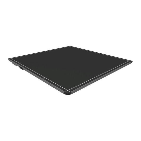
Varex Imaging 4343W Manual (112 pages)
X- ray Detectors
Brand:
Varex Imaging
| Category:
Security Sensors
| Size: 1 MB
Table of Contents
Table of Contents
13
Scope
23
Contraindication
23
Intended Use
23
Audience
23
Abbreviations
24
References
24
Table 1 Abbreviations
24
Table 2 References
24
Definition of Symbols
25
Table 3 Definition of Symbols
25
Standards and Regulations
27
Table 4 Standards and Regulations
27
Storage and Use Conditions
28
Table 5 Environmental Conditions
28
Temperature Sensors
29
Table 6 Temperature Sensor Min and Max
29
Description of the X-Ray Detectors
30
Figure 1 Typical Detector Configuration
30
X-Ray Detector Specifications
31
Table 7 Specifications
31
X-Ray Detector Surfaces and Features
35
Table 8 Description of Detector Surfaces and Features
35
Figure 2 4343W X-Ray Detector Surfaces and Features
35
Table 9 Description of Detector Surfaces and Features
36
Figure 3 4336W-G5 X-Ray Detector Surfaces and Features
36
Table 10 Description of Detector Surfaces and Features
37
Figure 4 2530W-G5 X-Ray Detector Surfaces and Features
37
Getting Started
38
Shipment Contents
38
Data Interface and Cables
38
Connecting the Service Cable for 4343W
39
Figure 5 X-Ray Detector as Access Point
39
Figure 6 X-Ray Detector with Router
39
Figure 7 Service Cable Connection (4343W Only)
40
Connecting the Tether Cable for 4336W-G5 and 2530W-G5
41
Figure 8 Remove the Overlay
41
Figure 9 Remove the Screw and the USB Door
41
Figure 10 Tether Cable Connection 4336W-G5 and 2530W-G5
42
Software Installation
43
SDK Files
43
Bonjour Installation Files
43
Sample Code
44
Utility Software
44
Viva Installation
44
Figure 11 Setup
44
X-Ray Detector Battery
45
Battery Installation
45
Figure 12 Representation of Battery Installation
45
Battery Removal
46
Figure 13 Unlatch Battery
46
Figure 14 Battery Removal
46
Battery Charge Level
47
Battery Hot-Swap
47
Table 11 Battery Hot-Swap Operation Time
47
Figure 15 Battery Charge Level
47
Optional Varex Provided Inductive Battery Charger
48
Installing the Varex Provided Inductive Battery Charger
48
Figure 16 Varex Inductive Battery Charger Dimensions (in MM) and Mounting Hole Locations (4343W and 4336W-G5 and 2530W-G5)
49
Figure 17 VHB Tape Placement Locations on Varex Inductive Battery Charger
50
Figure 18 VHB Tape Placement Dimension on Varex Inductive Battery Charger
50
Using a Third-Party Inductive Battery Charger
51
Figure 19 Third-Party Inductive Battery Charger 4343W/4336W-G5/2530W-G5 X-Ray Detector Alignment
51
Power-On and Power-Off Sequence
52
Reboot Sequence
53
Figure 20 Reboot Sequence
53
LED Status Indicator Behavior
54
Table 12 LED Status Details
54
Figure 21 LED Status Indicator
54
Connecting to the X-Ray Detector
55
Figure 22 the Viva Icon
55
Figure 23 Detector Linked in Viva
55
VSP Control Panel
56
11.11.1 Access the VSP Control Panel
56
Figure 24 VSP Control Panel Access Authentication
56
Figure 25 VSP Control Panel
57
11.11.2 Modify Settings
58
Figure 26 Modify VSP Control Panel Settings
58
11.11.3 Change Password
59
Figure 27 Change Password
59
11.11.4 Firmware Update
60
Figure 28 Updating the Firmware
60
Figure 29 Firmware Updated
61
X-Ray Detector Calibration
62
11.12.1 Offset Calibration
62
11.12.2 Offset Calibration Steps
62
Figure 30 Mode Drop down Menu
62
Figure 31 Initiate Offset Calibration
63
Figure 32 Calibration Setting Window
63
Figure 33 Offset Calibration Progress
63
11.12.3 Gain Calibration
64
Figure 34 Finish Offset Calibration
64
11.12.4 Gain Calibration Steps
66
Table 13 Gain Calibration Sequence in Viva- All Modes
66
Figure 35 Mode Drop down Menu
66
Figure 36 Initiate Gain Calibration
66
Figure 37 Gain Calibration Progress Window
67
Figure 38 Gain Calibration Updating
67
Figure 39 Gain Calibration Complete
68
Image Acquisition
69
Table 14 Types of Corrections that Can be Applied During Acquisition
69
Figure 40 Radiographic Acquisition Settings
69
11.13.1 Acquiring Radiography Images
70
Figure 41 Radiographic Acquisition Settings Window
70
Figure 42 Mode Drop down Menu
70
Figure 43 Acquire Image Button
71
Figure 44 Acquire Image
71
Figure 45 Start Acquisition
72
Figure 46 Image Acquisition Progress
72
11.13.2 Radiographic Acquisition Settings
73
Viva Configuration Settings
73
Figure 47 Acquisition Type Drop down Menu
73
Figure 48 Mode Drop down Menu
73
Figure 49 Hardware Handshaking Not Selected
74
Figure 50 Hardware Handshaking Selected
74
Figure 51 Open System Settings
75
Figure 52 System Settings Window
75
Dynamic Integration Settings
76
Figure 53 Select Mode
76
Figure 54 Acquire Image Setup
76
Figure 55 Message Box
77
Figure 56 Enter Integration Time
77
The Detector Configuration File
78
Table 15 Operational Mode Example
78
System Software
79
Radiography Acquisition
79
Figure 57 Exposure: Corrected Frames
79
Vtrigger Acquisition (AED)
80
Figure 58 Exposure: Raw Frames
80
X-Ray Generator Interface Signals
81
Position Sensing
81
Figure 59 Position Sensors
81
Autonomous Mode
82
Detector Sharing
82
Maintenance
83
Cleaning and Disinfecting
83
Material Compatible Chemicals for Cleaning and Disinfecting
83
Cleaning the X-Ray Detector
84
Disinfecting the X-Ray Detector
84
Field Replaceable Parts
85
Troubleshooting
86
Table 16 Problems and Solutions
86
After-Sales Service for Varex Imaging Products
90
Disposing of the X-Ray Detector and Battery
90
Safety - Electromagnetic Interference
91
Electromagnetic Emissions
91
Table 17 4343W Radiated/Conducted Emissions, Harmonics, Voltage, Fluctuations & Flicker
91
Electromagnetic Immunity
92
Table 18 4336W-G5 and 2530W-G5 Radiated/Conducted Emissions, Harmonics, Voltage, Fluctuations & Flicker
92
Table 19 4343W ESD, Transient/Burst, Surge, Voltage Variation, Magnetic Fields
93
Table 20 4343W Test Specs for Enclosure Port Immunity to RF Wireless Communications Equipment
94
Table 21 4336W-G5 and 2530W-G5 ESD, Transient/Burst, Surge, Voltage Variation, Mag- Netic Fields
96
Table 22 4336W-G5 and 2530W-G5 Test Specs for Enclosure Port Immunity to RF Wireless
96
Radio Frequency (RF) Compliance Information
98
United States FCC/IC Compliance
98
Figure 60 4343W Detector and Wireless Label Locations
99
Figure 61 4336W-G5 Detector and Wireless Label Locations
100
Figure 62 2530W-G5 Detector and Wireless Label Locations
100
Regulatory
101
Industry Canada Notice
101
Declaration of Conformity for European Union
103
Table 23 Europe - Declaration of Conformity in Languages of European Community
103
Korea Certification
104
Table 24 Korea Certification
104
Appendix A: Accessories
105
Table 25 Accessories
105
Appendix B: Mechanical Drawings
106
Figure 63 4343W X-Ray Detector Dimensions in MM
106
Figure 64 4343W X-Ray Detector Dimensions in MM
106
Figure 65 4336W-G5 X-Ray Detector Dimensions in MM
107
Figure 66 4336W-G5 X-Ray Detector Dimensions in MM
107
Figure 67 2530W-G5 Detector Dimension in MM
108
Figure 68 2530W-G5 Detector Dimension in MM
108
Advertisement
Varex Imaging 4343W Manual (90 pages)
X-ray Detector
Brand:
Varex Imaging
| Category:
Security Sensors
| Size: 3 MB
Table of Contents
Table of Contents
13
1 Scope
21
2 Contraindication
21
3 Intended Use
21
4 Audience
21
5 Abbreviations
22
6 Definition of Symbols
22
Table 1 Abbreviations
22
Table 2 Explanation of Symbols
22
7 Standards and Regulations
24
Table 3 Standards and Regulations
24
8 Description of the 4343W
25
Figure 1 Typical Detector Configuration
25
Figure 2 Imaging System Overview - as Access Point
26
Figure 3 Imaging System Overview - with Router
26
Figure 4 Imaging System Overview - Service Cable Connection
27
Shipment Contents
27
Optional Parts
28
Table 4 Optional Parts and Accessories
28
Figure 5 X-Ray Detector Surfaces and Features
29
Table 5 X-Ray Detector Surfaces and Features
29
X-Ray Detector Surfaces and Features
29
Figure 6 X-Ray Detector Dimensions
30
Figure 7 X-Ray Detector Dimensions
30
X-Ray Detector Dimensions
30
X-Ray Detector Specifications
31
Table 6 X-Ray Detector Specifications
32
Environmental Considerations
33
Table 7 Environmental Conditions
33
X-Ray Detector Battery
34
Battery Installation
34
Figure 8 Representation of Battery Installation
34
Battery Removal
35
Figure 9 Unlatch Battery
35
Figure 10 Battery Removal
35
Battery Charge Level
36
Battery Hot-Swap
36
Optional Varex Provided Inductive Battery Charger
36
Installing the Varex Provided Inductive Battery Charger
36
Figure 11 Battery Charge Level
36
Figure 12 Varex Inductive Battery Charger Dimensions and Mounting Hole Locations
37
Figure 13 VHB Tape Placement Locations on Varex Inductive Battery Charger
38
Figure 14 VHB Tape Placement Dimension on Varex Inductive Battery Charger
38
Designing a Custom Inductive Battery Charger
39
Figure 15 Third-Party Inductive Battery Charger and 4343W X-Ray Detector Alignment
40
Using a Third-Party Inductive Battery Charger
40
Figure 16 Reboot Sequence
41
Power-On and Power-Off Sequence
41
Reboot Sequence
41
Figure 17 LED Status Indicator
42
LED Status Indicator Behavior
42
Position Sensing
42
Table 8 LED Status Details
42
Detector Sharing
43
9 The Detector Configuration File
43
Table 9 Operational Mode Example
43
10 System Software
44
Radiography Acquisition
44
Figure 18 Exposure: Corrected Frames
44
Vtrigger Acquisition (AED)
45
Figure 19 Exposure: Raw Frames
45
X-Ray Generator Interface Signals
46
SDK Installation
46
SDK Files
46
Bonjour Installation Files
47
Sample Code
47
Utility Software
47
X-Ray Detector Calibration
48
Offset Calibration
48
Offset Calibration Steps
48
Figure 20 Mode Drop down Menu
48
Figure 21 Initiate Offset Calibration
49
Figure 22 Calibration Setting Window
49
Figure 23 Offset Calibration Progress
50
Figure 24 Finish Offset Calibration
50
Gain Calibration
51
Table 10 Gain Calibration Sequence - All Modes
52
Gain Calibration Steps
53
Figure 25 Mode Drop down Menu
53
Figure 26 Initiate Gain Calibration
53
Figure 27 Gain Calibration Progress Window
54
Figure 28 Gain Calibration Updating
54
Figure 29 Gain Calibration Complete
55
Linking to the X-Ray Detector
56
Figure 30 the Viva Icon
56
Figure 31 Detector Linked in Viva
56
Viva Configuration Settings
57
Figure 32 Mode Drop down Menu
57
Figure 33 Hardware Handshaking Not Selected
57
Figure 34 Hardware Handshaking Selected
58
Figure 35 Open System Settings
58
Image Acquisition
59
Figure 36 System Settings Window
59
Table 11 Types of Corrections that Can be Applied During Acquisition
59
Figure 37 Radiographic Acquisition Settings
60
Figure 38 Radiographic Acquisition Settings Window
60
Acquiring Radiography Images
61
Figure 39 Mode Drop down Menu
61
Figure 40 Acquire Image Button
61
Figure 41 Acquire Image
62
Figure 42 Start Acquisition
62
Figure 43 Image Acquisition Progress
63
Figure 44 Acquisition Type Drop down Menu
63
Radiographic Acquisition Settings
63
VSP Control Panel
64
Access the VSP Control Panel
64
Figure 45 VSP Control Panel Access Authentication
64
Figure 46 VSP Control Panel
65
Modify Settings
66
Figure 47 Modify VSP Control Panel Settings
66
Change Password
67
Figure 48 Change Password
67
Firmware Update
68
Figure 49 Updating the Firmware
68
Figure 50 Firmware Updated
69
11 Maintenance
70
Cleaning and Disinfecting
70
Material Compatible Chemicals for Cleaning and Disinfecting
70
Cleaning the X-Ray Detector
71
Disinfecting the X-Ray Detector
71
Field Replaceable Parts
72
12 Troubleshooting
73
Table 12 Problems and Solutions
73
After-Sales Service for Varex Imaging Products
76
13 Disposing of the X-Ray Detector and Battery
76
14 Safety - Electromagnetic Interference
77
Electromagnetic Emissions
77
Table 13 Radiated/Conducted Emissions, Harmonics, Voltage, Fluctuations & Flicker
77
Electromagnetic Immunity
78
Table 14 ESD, Transient/Burst, Surge, Voltage Variation, Magnetic Fields
78
Table 15 Test Specs for Enclosure Port Immunity to RF Wireless Communications
79
Radio Frequency (RF) Compliance Information
81
United States FCC Compliance
81
15 Regulatory
83
Industry Canada Notice
83
Table 16 Europe - Declaration of Conformity in Languages of European Community
85
Advertisement
Related Products
Varex Imaging 4336W-G5
Varex Imaging Azure 4131Z
Varex Imaging Optica 40 Series
Varex Imaging 2315NDT
Varex Imaging 2530C-G5
Varex Imaging 2530W-G5
Varex Imaging Azure 3131Z
Varex Imaging PaxScan 1313DXT-I
Varex Imaging PaxScan 1515DXT-I
Varex Imaging PaxScan 2520DX-I
Varex Imaging Categories
Security Sensors
Medical Equipment
Battery Charger
Air Conditioner
Laboratory Equipment
More Varex Imaging Manuals
Login
Sign In
OR
Sign in with Facebook
Sign in with Google
Upload manual
Upload from disk
Upload from URL