Table of Contents
Advertisement
Quick Links
SMARTER WATER HEATING
WATER
ELECTRIC TANKLESS
POINT OF USE
OR
NEXT GENERATION
MOLECULAR HEAT TECHNOLOGY
ON-DEMAND FLOW
ADVANCED ENERGY AND
TEMPERATURE CONTROL
FLEXIBLE, EASY, AND
SPACE-SAVING INSTALLATION
PREVENTS BACTERIA GROWTH
TEMPERATURE ADJUSTABLE
TO AVOID WATER SCALDING
DOES NOT SCALE WHILE HEATING
INSTALLATION
& OPERATION
MANUAL
MH SERIES 6
CONTINUOUS FLOW ELECTRIC WATER HEATER
CFEWH SERIES 6-13 | SINGLE PHASE - USA
|
INSTALLATION MANUAL for CFEWH SERIES 6-13
HEATER
MULTI POINT USE
|
V01 - 12 / 02 / 2021
LEARN MORE AT
MICROHEAT.US/INFO
OR SCAN CODE:
Page 1 of 17
Advertisement
Table of Contents

Subscribe to Our Youtube Channel
Related Manuals for MicroHeat MH 6 Series


Summary of Contents for MicroHeat MH 6 Series
- Page 1 TO AVOID WATER SCALDING DOES NOT SCALE WHILE HEATING INSTALLATION & OPERATION MANUAL LEARN MORE AT MICROHEAT.US/INFO MH SERIES 6 OR SCAN CODE: CONTINUOUS FLOW ELECTRIC WATER HEATER CFEWH SERIES 6-13 | SINGLE PHASE - USA Page 1 of 17...
-
Page 2: Table Of Contents
CONTENTS Introduction to CFEWH ............1 Benefits of CFEWH ............... 2 Installation Options ..............3 Components and Dimensions ..........4 Specifications ............... 5 Pre-Installation Checklist ............6 Installation Overview ............. 7 Electrical Installation ..... 8-10 BY A LICENSED ELECTRICIAN ONLY Plumbing Installation ..... -
Page 3: Introduction To Cfewh
INTRODUCTION TO CFEWH This installation manual covers the premium model of the MicroHeat Continuous Flow Electric Water Heater [CFEWH] SERIES 6-13. Units include displays showing output water temperature (settable up to 140°F, temperatures below 120°F are recommended to prevent scalding), and flow rate. -
Page 4: Benefits Of Cfewh
BENEFITS OF CFEWH KEY BENEFITS DECREASED INFRASTRUCTURE COSTS › Setting the water temperature on the unit below 120°F or less will prevent user scalding, unless otherwise specified. › Point-of-use installation significantly reduces requirement for hot water reticulation infrastructure. SMALL FOOTPRINT ›... -
Page 5: Installation Options
INSTALLATION OPTIONS Here are some suggested options SINGLE UNIT for installation. The flexibility of the OPTION unit allows custom solutions for your needs, whether point-of-use or PRESSURE LIMITING multi-point-use. Please note that the COLD VALVE location and installation of the unit is WATER WATER SHUTOFF VALVE... -
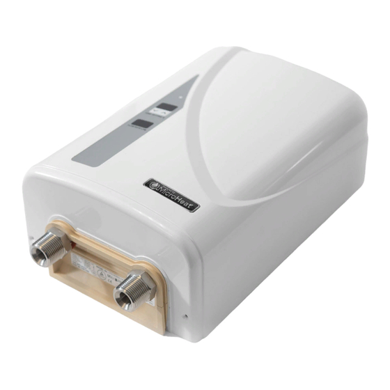
Page 6: Components And Dimensions
COMPONENTS AND DIMENSIONS PARTS Chassis Top Cover Heat Sink Flow Rate Sensor Temperature Sensor, Receptacle, Cable and Plug Assembly ¾ � NPT Inlet Water Connection ¾ � NPT Outlet Water Connection Printed Circuit Board Assembly × 3 (PCBA) V7.4 (NOT INCLUDED) Earth Locking Mechanism SERIES 6-13 Exterior Cover (Premium) -
Page 7: Specifications
SPECIFICATIONS All specifications, stated operational flow rates, and output water temperatures are valid within the range of water conductivity: › 80μS/cm to 1300μS/cm + 15% at 68°F (μS–microSiemens) › 1.25kΩ-cm to 7.7kΩ-cm + 15% at 68°F NOTE: Water conductivity may be less than 80μS/cm. Reduce flow rate to achieve comfortable water temperature. Water conductivity greater than 1300μS/cm + 15% will generate an error condition. -
Page 8: Pre-Installation Checklist
CONNECT TO A SALT-REGENERATED WATER SOFTENER OR A WATER SUPPLY OF SALT MicroHeat, nor its Distributors, will be liable for any WATER. damages due to failure to comply with the installation and operating instructions outlined in this manual or through Failure to comply with the installation and improper use. -
Page 9: Installation Overview
INSTALLATION OVERVIEW STEP 1 Pages 8-10 ELECTRICAL INSTALLATION BY A LICENSED ELECTRICIAN ONLY The unit is to be connected with fixed wired power (Live 1 and Live 2) and a ground wire (Ground Earth). Once active wires are connected to the unit, the unit must be mounted into position and tested for connectivity. - Page 10 ELECTRICAL INSTALLATION FOR LICENSED ELECTRICIANS ONLY PAGE 1 of 3 AFTER DIVERSITY MAXIMUM DEMAND As per National Electrical Code (NEC), the current in a circuit must not PART I GENERAL exceed the current rating of the circuit protective device and this, in turn, must not exceed the current carrying capacity of the circuit conductors.
- Page 11 ELECTRICAL INSTALLATION FOR LICENSED ELECTRICIANS ONLY PAGE 2 of 3 The appliance must be connected to the mains ELECTRIC MAINS SUPPLY CABLE GLAND supply with fixed wiring. It is recommended that an appropriate mains isolation switch be installed in-line with the fixed DISPLAY PCBA PLUG wiring electrical supply.
- Page 12 ELECTRICAL INSTALLATION FOR LICENSED ELECTRICIANS ONLY PAGE 3 of 3 STEPS FOR INSTALLATION (cont.) Ensure the circuit breaker and the isolation switch (if installed) supplying the 220 - 240VAC electrical mains to the CFEWH are SCREW PLACEMENT SCREW PLACEMENT turned OFF. CENTER CENTER Electricity supply cable installation:...
-
Page 13: By A Licensed Plumber Only
Outlet Water Connections are both ¾ � NPT. NOTE: Flush the cold water line before connecting to the unit. IMPORTANT: MicroHeat, nor its Distributors, Connect the hot water from the Outlet Water Connection. will be liable for any damages through failure to comply with Run water through the unit without power to ensure there are no leaks. -
Page 14: Preparation For Use
PREPARATION FOR USE After installation, this two-step procedure must be followed. STEP 1: FLUSH › Flushing is required to clear the unit of plumbing debris that may have collected in the piping during installation. › This is done with the electric power supply turned off. ›... -
Page 15: Optimized Energy Usage
OPTIMIZED ENERGY USAGE The table below shows the flow rate in gallons per minute (gpm), related to deliverable output water temperature (°F) and optimized electrical energy usage (kW). The table shows you the results that can be achieved by varying the water flow and temperature. -
Page 16: Operating The Cfewh
“) will be in the FLOW RATE DISPLAY. See page 16 for full list of error codes. For any additional service questions, contact our customer service at support@microheat.us. Page 14 of 17 INSTALLATION MANUAL for CFEWH SERIES 6-13 V01 - 12 / 02 / 2021... -
Page 17: Diagnostics And Error Descriptions
DIAGNOSTICS AND ERROR DESCRIPTIONS LED DISPLAY ERROR CODE ERROR DESCRIPTION / CAUSE ERROR TYPE No Color Not powered No Error GREEN Slow Flashing Normal operation: STANDBY No Error GREEN Fast Flashing Normal operation: HEATING No Error ORANGE In priming mode No Error Flashing Water conductivity too low... -
Page 18: Maintenance
MAINTENANCE MANUAL INTERVENTION IMPORTANT: The MANUAL INTERVENTION procedure must only be performed by a licensed professional. An IRRESOLVABLE / MECHANICAL LOCKOUT ERROR may be resolved by resetting the unit by pressing PCBA RESET Button. This can be done by following these steps: LED INDICATOR DISPLAY PCBA PLUG Remove the... -
Page 19: Warranty
CFEWH water heater. 4. Where the CFEWH is located in a position that does not comply with the MicroHeat CFEWH Installation Instructions or relevant statutory requirements. - Page 20 52048 Shelby Parkway Shelby Charter Township, MI 48315 Please contact our customer service at: support@microheat.us MicroHeat® is a registered trademark of the U.S. Patent and Trademark Office. Made in Australia US Patent No. US 7,050,706 B2 Intl PCT Patent No. W003/016791 MicroHeat Technologies Pty Ltd.
Need help?
Do you have a question about the MH 6 Series and is the answer not in the manual?
Questions and answers