Advertisement
Quick Links
Advertisement

Subscribe to Our Youtube Channel
Related Manuals for HERO A450


Summary of Contents for HERO A450
- Page 1 A450 – A460 Automatic Colorant Dispenser USER MANUAL...
- Page 2 TintWise®, together with an integrated electronic formula book (EFB) and database will allow you to operate your HERO automatic dispenser as a stand-alone unit. It will also interface with most third-party color matching systems and spectrophotometers, allowing for a seamless transfer of EFB and custom formulas to the dispenser.
- Page 3 HERO Products Group 720 Eaton Way Delta, BC V3M 6J9 Canada Declares that: The Automatic Dispenser model: EUREKA A450 – A460 Serial number: ___________ Is in compliance with: CAN/CSA-C22.2 No. 61010.1-04 Safety Requirements for Electrical Equipment for Measurement, Control and...
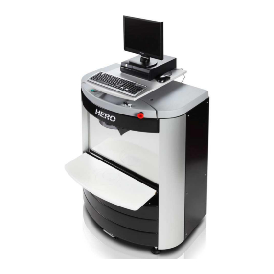
- Page 4 EUREKA Automatic Dispenser Key Personal Computer Electrically powered can shelf Canister cover Colorant canisters Can shelf buttons Emergency Stop button Nozzle head cover...
- Page 5 PC sliding shelf Identification Label with model and serial numbers Cartridge Pumps Electronic Board (PCB) Ground Main switch and connections power supplier plug USB comm. cable...
-
Page 6: General Information
GENERAL INFORMATION This manual contains information to help an operator to begin using the HERO Eureka A450/A460 automatic colorant dispenser and insure ease of use and proper maintenance. Please read this manual carefully and completely before using or servicing your HERO automatic colorant dispenser. -
Page 7: Warranty
HERO. The warranty period begins when the equipment is shipped from HERO’s manufacturing facilities. HERO may, at its own discretion, start the warranty period at a later date due to shipping, installation or other delays. -
Page 8: Safety Instructions
All conditions, instructions and specifications outlined in this manual must be followed in good faith and any questions or issues must be brought to the attention of a HERO authorized representative in a timely manner. - Page 9 DISPENSER POSITIONING AND INSTALLATION Unpacking the dispenser Remove all shrink wrap from around the container and pallet. Remove the fastening straps placed around the outside of the box(es). If a PC is included, removed its boxes from atop the dispenser and place them in a safe area.
- Page 10 Pull the USB cable out carefully. If you encounter resistance call HERO’s Help Desk. Connect it to one of the USB ports on the PC...
- Page 11 You should now hear the dispenser’s agitation motors turn on and by removing one of the canisters’ lids, you should see its agitation paddles turning. Call HERO’s Help Desk if the agitation motors do not turn on after powering up the dispenser. The motors should run for approximately 3 minutes after power is turned on.
- Page 12 CARTRIDGE PUMP REPLACEMENT When a cartridge pump needs to be replaced complete the following steps: Disconnect the dispenser from its AC power source. Remove the lower rear panel on the back of the dispenser. Remove the wiring connector to the pump’s motor on the pump you want to change. Use a large flat-tip screwdriver to close the shut-off valve above the pump cartridge.
- Page 13 CARTRIDGE PUMP REPLACEMENT (Cont.) Clean all colorant residue from the area around the pump. Make sure there is no colorant on the wiring connector. Restore power to the dispenser and test the new pump cartridge by dispensing some colorant. Dispense enough colorant to ensure that all the air is removed from the line.
- Page 14 It is very important to keep the sponge clean and wet to maintain the nozzle tips in good working order. HERO recommends that the sponge and cup be removed and rinsed each morning, leaving the sponge wet with some water in the cup.
- Page 15 TELESCOPIC SHELF ACTUATOR The Eureka automatic dispenser is equipped with a telescopic actuator that raises and lowers the can shelf. This device allows for the tinting of various size cans along with the use of the quart/pint locator included with the dispenser as well as the optional pull-out shelf that can be used with sample (half-pint) cans.
- Page 16 Place the new telescopic column in the dispenser as shown in pictures A, B and C. Secure the new telescopic column with the four screws previously removed (Picture D). The dispenser will need to be raised or tilted backwards to reach these screws.
- Page 17 SIMULTANEOUS ELECTRONIC BOARD (PCB) The simultaneous colorant dispenser allows up to four colorants to be dispensed simultaneously. The electronic board (PCB) is secured in the dispenser in such a way as to simplify its removal and replacement. To remove and replace the PCB, please proceed as follows and refer to the pictures on the next page: Disconnect the dispenser from its AC power source.
- Page 18 Electronic board (PCB) Sliding tray Wiring harnesses Mounting hardware...
- Page 19 DISPENSE TUBE REPLACEMENT Dispense tubes or hoses connect the output side of the pumps to the corresponding nozzles in the dispense head located in the upper front section of the dispenser. To replace a dispense tube, please proceed as follows: Access the “Empty dispense tube”...
- Page 20 Select the circuit that has to be emptied and click on Next. Click on the OK button in the dispense window (Pictures I and J). Picture I Picture J...
- Page 21 AC power source. Remove the lower rear panel on the back of the dispenser. Remove the plastic semi-circular cover with the HERO logo that covers the upper dispense nozzle area. From behind the dispenser, remove the locking nut on the hose that connects to the pump housing (Picture K).
- Page 22 AGITATION MOTOR REPLACEMENT The agitation paddles inside the Eureka canisters are operated by a 24 VDC motor located on the bottom of each canister. To remove and replace an agitation motor, please proceed as follows: Disconnect the dispenser from its AC power source. Remove the lower rear panel on the back of the dispenser.
-
Page 23: Equipment Specifications
EQUIPMENT SPECIFICATIONS Description: EUREKA Automatic Colorant Dispenser Capacity: Max 24 canisters, 5 liters and 3 liters Pumps: Each circuit to be used with water or glycol based colorants uses a dedicated progressive cavity pump consisting of a hardened and chromed metal rotor with increased abrasion resistance and a stator made from Viton elastomer. -
Page 24: Recommended Spare Parts
RECOMMENDED SPARE PARTS PART # DESCRIPTION PICTURE Cartridge pump Standard flow A45500 High flow A45525 Solvent based A45502 Solvent based/High flow A45532 2.5 mm Nozzle Long elbow A20352 Short elbow A10262 Automatic nozzle cap A10305 Long arm A10205 Short arm A45560 24 VDC Agitation motor... - Page 25 RECOMMENDED SPARE PARTS (Cont.) PART # DESCRIPTION PICTURE 24 VDC Telescopic shelf actuator A45805 Electronic control board (PCB) A10720 Simultaneous 24 VDC A45772 Switching power supply 67 VDC Switching A10773 power supplier...
- Page 26 RECOMMENDED SPARE PARTS (Cont.) PART # DESCRIPTION PICTURE A45765 Power supply to PCB wiring harness A45740 Stepper motor and A45741 agitation motor to PCB wiring harness A45742 A45743 lengths L1, L2, L3, L4...
-
Page 27: Troubleshooting Chart
TROUBLESHOOTING CHART Contact HERO’s 24/7 Help Desk with any questions: 1-800-494-4376 PROBLEM CAUSE SOLUTION Colorant leaking from the stepper Damaged pump seals Replace cartridge pump motor connected to the cartridge pump Colorant dripping from the nozzle Aerated colorant Dispense colorant until you see a... - Page 28 TROUBLESHOOTING CHART (Cont.) The pump motor runs normally, No colorant inside the canister Add colorant to the canister and however, no colorant comes out of prime the line to remove any air the nozzle The canister nozzle is obstructed Clean or replace the nozzle Clogged line Remove as much colorant as possible from the canister and add...
-
Page 29: Standard Parameters
STANDARD PARAMETERS The following charts show several parameters used in the dispenser’s operation along with their respective default values. PARAMETER MEANING DEFAULT VALUE Mixing – Time ON 3 min – 0 sec Agitation time ON Mixing – Time OFF 120 min – 0 sec Agitation time OFF Pumps –... - Page 30 Parameter Images...
- Page 31 BASIC TINTWISE® OPERATIONS Main Dispense Screen LOGIN - Allows login of different user levels. A password is required. CANISTERS - Selecting this button will take you to the canister screen where you can purge, agitate, and change the canisters’ levels. EXIT - Exits TintWise®...
- Page 32 BASIC TINTWISE® OPERATIONS (Cont.) How to Dispense Select the appropriate collection, product and formula from the database within TintWise® or from your color matching system (Match-Rite, Datacolor, etc). When selecting from a color matching system the last step should be to click on the dispense or tint button in that system. This will send the information to TintWise®.
- Page 33 BASIC TINTWISE® OPERATIONS (Cont.) Once dispensing has started, a graphical representation of the tint being dispensed will appear on the screen as shown above. It will show what colorant is currently being dispensed and how much more is needed to complete the requested formula. If at anytime you want to abort the dispensing process, click on the STOP button.
- Page 34 BASIC TINTWISE® OPERATIONS (Cont.) Fill canister – Opens the window pictured below allowing you to change the colorant level of an individual canister. Enter the appropriate amount and select Add. The colorant levels can also be changed by clicking on the field showing the numerical quantity of colorant (to the left of the fill canister icon) on the canister screen, typing the appropriate amount and pressing enter.
- Page 35 BASIC TINTWISE® OPERATIONS (Cont.) Dispense Queue Screen If the queue system is enabled you can access this screen by clicking on the dispense queue tab (next to the Custom and/or Standard tabs) from the Main Dispense Screen. The queue screen will show all the formulas sent to TintWise® from your database software. At this point you can dispense the formula from the list by clicking on it and then selecting the dispense button.
- Page 36 BASIC TINTWISE® OPERATIONS (Cont.) Manual Formula Screen To start, select the appropriate paint collection, product and can size from the tabs at the top of the window, if TintWise® has and internal database. If the database resides only in your color matching computer, then only the can size should be selected.
- Page 37 The following window will appear: Three (3) fields are displayed as “Key1”, “Key2”, and “Key3”. These labels or titles can be changed as per a store’s needs (contact HERO customer service @ 800-494-4376 for further details). These fields represent 3 different ways to save formulas using, for example, a customer’s name (Key1), formula name (Key2) and telephone number (Key3).
- Page 38 BASIC TINTWISE® OPERATIONS (Cont.) Edit Formula Screen This will allow you to edit whatever formula is displayed on the Main Dispense Screen. The EDIT FORMULA screen works the same way as the MANUAL FORMULA screen.
- Page 39 Do NOT use harsh chemicals or other abrasive materials. ✓ NEVER add any product other than the appropriate colorant to each canister. Call the HERO Help Desk if colorant or any other product is put into the wrong canister by mistake.
- Page 40 CUSTOMER MAINTENANCE PROCEDURES (Cont.) Before the colorants purge, a box will appear asking you to “Insert can remove cap”. At this point, remove the cup and sponge for cleaning. Do this before initiating the purge process. To remove the cup, hold the front portion and pivot it downwards so that the sponge faces you.
- Page 41 1 through 4 above until you are comfortable that the colorant is not contaminated with water and dispenses with no air. It should dispense in an uninterrupted solid stream. Follow all local regulations in disposing of waste contaminated with colorant. For any additional information, please contact HERO’s 24/7 Help Desk at 800-494-4376.
Need help?
Do you have a question about the A450 and is the answer not in the manual?
Questions and answers