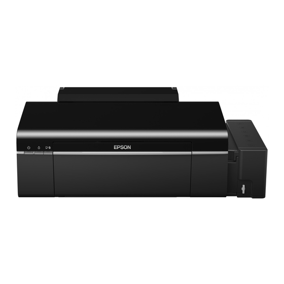
Epson L800 Service Manual
Hide thumbs
Also See for L800:
- Service manual (107 pages) ,
- User manual (96 pages) ,
- Start here (4 pages)
Summary of Contents for Epson L800
- Page 1 SERVICE MANUAL Color Inkjet Printer L800/L801 Confidential SEMF10-008 WWW.INKCLONERS.COM...
- Page 2 SEIKO EPSON CORPORATION. All effort have been made to ensure the accuracy of the contents of this manual. However, should any errors be detected, SEIKO EPSON would greatly appreciate being informed of them.
- Page 3 Safety Precautions All safety procedures described here shall be strictly adhered to by all parties servicing and maintaining this product. DANGER WARNING Strictly observe the following cautions. Failure to comply could result in Strictly observe the following cautions. Failure to comply may lead to personal serious bodily injury or loss of life.
- Page 4 Strictly observe the following cautions. Failure to comply may lead to personal injury or damage of the product. 1. Repairs on Epson product should be performed only by an Epson certified 11. Be extremely careful not to scratch or contaminate the following parts.
- Page 5 About This Manual This manual, consists of the following chapters, is intended for repair service personnel and includes information necessary for properly performing maintenance and servicing the product. Manual Configuration Symbols Used in this Manual CHAPTER 1. DISASSEMBLY / REASSEMBLY Various symbols are used throughout this manual either to provide additional information on a specific topic or to warn of possible danger present during a Describes the disassembly/reassembly procedures for main parts/units of...
- Page 6 Revision Status Revision Date of Issue Description April 6, 2011 First Release Confidential...
-
Page 7: Table Of Contents
L800/L801 Revision A CONTENTS Chapter 1 Disassembly/Reassembly 1.5.13 CR Unit....................52 1.5.14 ASF Unit....................54 1.1 Overview ......................10 1.5.15 Upper Paper Guide ................56 1.1.1 Tools ......................10 1.5.16 APG Sensor Assy .................. 57 1.1.2 Checks and Precautions before Disassembling ........10 1.5.17 Front Paper Guide Assy ................ - Page 8 L800/L801 Revision A 2.3 Banding Reduction System (BRS) Adjustment / Paper Feed Amount Profile (PFP) Correction......................83 2.3.1 Overview ....................83 2.3.2 Adjustment Procedure ................85 Chapter 3 Maintenance 3.1 Overview ......................89 3.1.1 Cleaning....................89 3.1.2 Service Maintenance ................89 3.1.3 Lubrication ....................
-
Page 9: Chapter 1 Disassembly/Reassembly
C H A P T E R DISASSEMBLY/REASSEMBLY Confidential... -
Page 10: Overview
1003963 2 pins (thinner than Ø2 mm) Strong tape 1032813 Note : All of the tools listed above are commercially available. EPSON provides the tools listed with EPSON tool code. Figure 1-1. How to Place the Ink Tank Assy Disassembly/Reassembly... - Page 11 1.1.2.2 Factors which Affect the Safety of Service Personnel such as EANS DO TO MINIMIZE THE INK SPILL Ink Leakage during Operation Ink may spill when removing the following parts from L800/L801. Even observing the points described in this section, ink may C A U T I O N This section describes the parts that may cause ink spill and the means to spill in the following situations.
- Page 12 C H E C K Ink valve P O I N T the procedure for L800/L801 is the same; the numbers of the tube and the location of the Ink Supply Tank Assy in the photos are different from those of L800/L801, though.
- Page 13 L800/L801 Revision A When the ink stops flowing from the tube, close the choke valve, and It is recommended that the ink in the Ink Supply Tank should C H E C K then connect the Ink Supply Tube back to the joint.
-
Page 14: Protection For Transportation
L800/L801 Revision A 1.1.3 Protection for Transportation Securing the Ink Tank Secure both sides of the Top Cover with strong tape (x2). • Before packing the printer for returning it to the user, secure it at the specified Align the unfolded end of strong tape (x5) with the edge of the •... -
Page 15: Making A Special Tool For Holder Contact
L800/L801 Revision A 1.1.4 Making a Special Tool for Holder Contact Points to be checked before packing the printer The Holder Contact (refer to ) can be easily removed by using a special p.38 The Valve Lever is on the position All the caps of the Ink Supply Tank tool. -
Page 16: Orientation Definition
L800/L801 Revision A 1.1.5 Orientation Definition 1.1.6 How to Unlock the Carriage Orientation descriptions used in the disassembly/reassembly procedures are as Unlocking the carriage is required for disassembly of some parts or follows. components. Carry out any of the following operations to unlock the carriage and move the carriage to other than its home position. -
Page 17: Disassembly/Reassembly Procedures
L800/L801 Revision A 1.2 Disassembly/Reassembly Procedures Reference page (A) 1.2.1 Overview Black letters indicate a “ 1.5.8 Ink System (p45)” part/unit not supplied as Main Board Unit This section describes procedures for disassembling the parts/units in a an ASP. flowchart format. For some parts/units, detailed procedures or precautions are provided (accordingly indicated by icons and cell's color). -
Page 18: Disassembly Flowchart
L800/L801 Revision A 1.2.2 Disassembly Flowchart START Paper Support (p 19) Printer Cover Stacker Assy Stacker Cover Cover Ink Tube Foot Assy (p 24) (p 24) (p 35) “ 1.3.3 Stacker Assy / Stacker Cover (p25)” Paper Support Assy Housing Upper... -
Page 19: Apg Unit
L800/L801 Revision A (p 18) Valve Position Refilling Ink Tube Valve Top Cover Bottom Cover Valve Lever Top Cover Label Label Label Holder Rear (p 61) (p 61) (p 61) (p 62) (p 63) (p 62) (p 61) Tube Valve... -
Page 20: Pf Encoder / Pf Scale
L800/L801 Revision A (p 18) “ 1.4.1 Main Board Unit (p27)” *: There are four Tube Holders installed in this printer. Depending on the target parts or units, the number of Main Board Unit Tube Holder* Tube Holders you should remove differs.


Need help?
Do you have a question about the L800 and is the answer not in the manual?
Questions and answers